EP0270265A1 - Making composite metal deposit by spray casting - Google Patents
Making composite metal deposit by spray casting Download PDFInfo
- Publication number
- EP0270265A1 EP0270265A1 EP87309972A EP87309972A EP0270265A1 EP 0270265 A1 EP0270265 A1 EP 0270265A1 EP 87309972 A EP87309972 A EP 87309972A EP 87309972 A EP87309972 A EP 87309972A EP 0270265 A1 EP0270265 A1 EP 0270265A1
- Authority
- EP
- European Patent Office
- Prior art keywords
- metal
- sprays
- substrate
- deposit
- streams
- Prior art date
- Legal status (The legal status is an assumption and is not a legal conclusion. Google has not performed a legal analysis and makes no representation as to the accuracy of the status listed.)
- Granted
Links
Images
Classifications
-
- C—CHEMISTRY; METALLURGY
- C23—COATING METALLIC MATERIAL; COATING MATERIAL WITH METALLIC MATERIAL; CHEMICAL SURFACE TREATMENT; DIFFUSION TREATMENT OF METALLIC MATERIAL; COATING BY VACUUM EVAPORATION, BY SPUTTERING, BY ION IMPLANTATION OR BY CHEMICAL VAPOUR DEPOSITION, IN GENERAL; INHIBITING CORROSION OF METALLIC MATERIAL OR INCRUSTATION IN GENERAL
- C23C—COATING METALLIC MATERIAL; COATING MATERIAL WITH METALLIC MATERIAL; SURFACE TREATMENT OF METALLIC MATERIAL BY DIFFUSION INTO THE SURFACE, BY CHEMICAL CONVERSION OR SUBSTITUTION; COATING BY VACUUM EVAPORATION, BY SPUTTERING, BY ION IMPLANTATION OR BY CHEMICAL VAPOUR DEPOSITION, IN GENERAL
- C23C4/00—Coating by spraying the coating material in the molten state, e.g. by flame, plasma or electric discharge
- C23C4/12—Coating by spraying the coating material in the molten state, e.g. by flame, plasma or electric discharge characterised by the method of spraying
- C23C4/123—Spraying molten metal
Definitions
- This invention is concerned with a method of making a composite metal deposit by spray casting.
- the technique of spray casting is well known and comprises the steps of atomising a stream of molten metal to form a spray of hot metal particles by subjecting the stream to a relatively cold gas directed at the stream, and despositing the spray on a substrate.
- the provision of rapid and controlled cooling permits the production of deposits having unusual microstructures, which can be rolled or formed into shaped articles. But with only one source of molten metal, there is a limit to the range of compositions and microstructures that can be obtained.
- GB 8606733 describes a spray casting method which includes the step of applying to the stream or spray fine, solid particles of a material of different composition from the metal. The particles are incorporated in the deposit.
- refractory particles e.g. of alumina or silicon carbide can result in metal matrix composites having enhanced properties.
- US Patent 4522784 describes a casting method in which two streams of molten metal are mixed just prior to casting, the smaller stream having a higher temperature than the larger stream and being chosen so that a fine intermetallic precipitate is formed during and prior to casting. With the DC casting methods described, it is difficult to remove heat fast enough from the system to prevent to re-solution of the intermetallic precipitates.
- GB 1359486 describes a spray casting technique for casting two immiscible metals of different density. A single flow of molten metal consisting of concentric streams of the two metals is atomised and the drops collected on a substrate. The range of alloy compositions that can be cast in this way is quite restricted.
- This invention provides a convenient way of making composite metal deposits by spray casting, which is characterized over the above prior art by the fact that separate streams of molten metal are atomised separately. As a result, there is much less restriction on the compositions of the two metals.
- GB 1083003 describes a method of making bearing materials by spraying A1 and Pb simultaneously onto a backing strip. This results in a microstructure comprising alternating regions, of size corresponding (substantially) to the molten spray droplets, of A1 and Pb.
- US 3826301 contain a similar disclosure.
- the invention provides a method of making a composite metal deposit which method comprises providing a first metal stream, a second metal stream and a substrate, atomising the two streams to form first and second sprays of hot metal particles by subjecting the streams to relatively cold gas directed at the streams, and depositing the sprays consecutively on the substrate to form thereon a laminated depost.
- the first and second metal streams may be provided by gravity flow from holding vessels containing supplies of the molten metals.
- the invention contemplates the use of two, three or more molten metal streams, each being atomised separately, and references to first and second metal streams should be construed accordingly.
- Atomisation conditions may be chosen, as is known in the art, to control the size, velocity, direction and temperature of the sprays of hot metal particles.
- the particles of molten metal spread out in a conical spray pattern which may be of circular cross-section or may be modified, as known in the art, to form a different cross-section or a more even spread of metal particles.
- the substrate may be a metal surface, which may for example be flat or tubular with the metal spray to be deposited on the inner or the outer surface. It is generally preferred that the metal particles be still at least partially liquid on impact, otherwise the deposit may be too porous.
- the metal spray can be arranged to be partially or fully liquid but super-cooled on impact, so that solidifcation takes place immediately on impact and there is no need to extract large amounts of heat through the substrate.
- fibres, whiskers or particles of refractory material e.g. carbon or silicon carbide
- refractory material e.g. carbon or silicon carbide
- particles of refractory material can be incorporated in the first and/or second spray by the technique described in GB 8606733 noted above.
- Three (or more) sprays may be used.
- the spray patterns of two may be superimposed and operated simultaneously. This can result in a laminated structure in which alternate layers have a microstructure resulting from these two sprays.
- two superimposed sprays may be chosen to interact as described in the aforesaid US patent 4522784.
- the spray patterns of the first and second sprays may, but need not, overlap; that is to say, the two sprays may be arranged to impact on the same or different areas of the substrate.
- the substrate may be translated, or reciprocated, or rotated in order to pick up the two metal sprays.
- the two spray patterns of the two sprays do overlap, then it is necessary to operate the two sprays alternately in order to achieve the desired laminated structure. In order to operate both sprays continuously, it is therefoe preferred that the two spray patterns can be arranged not to overlap, and to reciprocate or rotate the substrate so that alternating layers of the two metals are deposited thereon.
- a first metal stream may be supplied initially, followed by the second, so that the deposit consists of the first metal with a surface coating of the second.
- the supply of molten metal in two or more streams gives the operator a great deal of latitude in determining the structure of a deposit.
- the laminated deposit comprises at least two layers of each metal in alternating superimposed relationship.
- the thickness of the alternating layers has a significant effect on the properties of the laminate.
- each layer preferably has a thickness in the range 0.01 - 100 mm, particularly 1 - 10 mm.
- the as-sprayed deposit may be subjected to rolling. For many purposes it is preferred that each layer in the rolled product have a thickness of from 10 to 500 microns, particularly 30 to 200 microns.
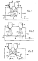
- Figures 1 to 3 are a schematic diagram of a system for making a composite metal deposit according to the invention.
- the system comprises first and second furnaces 10 and 12 for supplying first and second streams of molten metal, which are atomised (by means not shown) to form first and second sprays, 14 and 16, of hot metal particles.
- the spray patterns overlap, and each spray is operated in turn while the other is shut off.
- the sprays are deposited in turn on a substrate 18, whose position and orientation are controlled by means 20.
- the metal sprays and the substrate are contained within a spray chamber 22, which is closed except for an exit vent for gas and any overspray powder.
- a refractory material contained in a stream of carrier gas is supplied via a pipe 26 to the region where the first metal is atomised, and becomes incorporated in the first metal spray 14.
- the substrate 18 might be maintained stationary, so as to build up a composite metal body thereon; or it might be translated, rotated or reciprocated in order to build up a uniform composite metal layer.
- the substrate 18 might have taken the shape of a mould, with the intention of working the deposit while on the substrate to form a shaped article.
- the deposit will be substantially non-porous and will comprise alternating layers of the first and second metals.
- Figure 2 corresponds to Figure 1, except that the spray patterns of the two metal sprays 14 and 16 are shown as being non-overlapping. In this case, the sprays are operated continuously and the substrate 18 is reciprocated in order to obtain a deposit consisting of alternating layers of first and second metal.
- the spray patterns of the two metal sprays 14 and 16 are shown as partly overlapping when they impact on cylindrical substrate 18 which is caused to rotate round a horizontal axis 28.
- a fibre 30 is supplied from a spool 32 and becomes incorporated in the deposit.
- the first metal or alloy mentioned will generally be present in the deposit in a volume concentration as great or greater than the second metal or alloy.
- Laminated material was sprayed using a combination of 6061 Al alloy from on atomizer and 7475 Al alloy + SiC from the other atomizer.
- Both crucibles used were alumina with zirconia nozzles.
- the atomizing gas was nitrogen.
- the collector was an aluminium plate 300 mm long by 150 mm wide. The plate was reciprocated beneath the sprays at a frequency of 1Hz.
- the conditions for the 7475 alloy were the same apart from the melt temperature which was 710°C.
- SiC particulate (F600) was fed to the 7475 spray only, SiC was fed at a rate of 1.72 kg/min to the atomizing nozzle.
- the as - sprayed material was consolidated by hot rolling at 430°C to approximately 2 mm in thickness and then further cold rolling to 1 mm. Any as - sprayed porosity was found to close up during this process to form a fully consolidated product.
- the sheet was solution heat treated by holding for at least 30 min at 500°C and cold water quenching. The material was artificially aged for 20 hr at 120°C.
- results illustrate that the combination of the two materials in the laminate can result in improvements in mechanical poperties over the individual constituents.
- the results indicate an improvement in strength and ductility over 6061 and an improvement in ductility and crack initiation and propagation energy (indicating improved toughness) over the 7475 alloy with SiC.
- the results also indicate a significant improvement in the properties (notably ductility) over that of the 6061 alloy with SiC.
- the thickness of the laminated regions is highly important in controlling the final properties of the material - specifically in this instance the ductility and toughness of the laminate.
Landscapes
- Chemical & Material Sciences (AREA)
- Engineering & Computer Science (AREA)
- Mechanical Engineering (AREA)
- Plasma & Fusion (AREA)
- Chemical Kinetics & Catalysis (AREA)
- Materials Engineering (AREA)
- Physics & Mathematics (AREA)
- Metallurgy (AREA)
- Organic Chemistry (AREA)
- Coating By Spraying Or Casting (AREA)
- Laminated Bodies (AREA)
- Other Surface Treatments For Metallic Materials (AREA)
- Manufacture Of Alloys Or Alloy Compounds (AREA)
- Powder Metallurgy (AREA)
- Metal Rolling (AREA)
Abstract
Description
- This invention is concerned with a method of making a composite metal deposit by spray casting. The technique of spray casting is well known and comprises the steps of atomising a stream of molten metal to form a spray of hot metal particles by subjecting the stream to a relatively cold gas directed at the stream, and despositing the spray on a substrate. The provision of rapid and controlled cooling permits the production of deposits having unusual microstructures, which can be rolled or formed into shaped articles. But with only one source of molten metal, there is a limit to the range of compositions and microstructures that can be obtained.
- GB 8606733 describes a spray casting method which includes the step of applying to the stream or spray fine, solid particles of a material of different composition from the metal. The particles are incorporated in the deposit. The use of refractory particles e.g. of alumina or silicon carbide can result in metal matrix composites having enhanced properties.
- US Patent 4522784 describes a casting method in which two streams of molten metal are mixed just prior to casting, the smaller stream having a higher temperature than the larger stream and being chosen so that a fine intermetallic precipitate is formed during and prior to casting. With the DC casting methods described, it is difficult to remove heat fast enough from the system to prevent to re-solution of the intermetallic precipitates.
- GB 1359486 describes a spray casting technique for casting two immiscible metals of different density. A single flow of molten metal consisting of concentric streams of the two metals is atomised and the drops collected on a substrate. The range of alloy compositions that can be cast in this way is quite restricted.
- This invention provides a convenient way of making composite metal deposits by spray casting, which is characterized over the above prior art by the fact that separate streams of molten metal are atomised separately. As a result, there is much less restriction on the compositions of the two metals.
- GB 1083003 describes a method of making bearing materials by spraying A1 and Pb simultaneously onto a backing strip. This results in a microstructure comprising alternating regions, of size corresponding (substantially) to the molten spray droplets, of A1 and Pb. US 3826301 contain a similar disclosure.
- The invention provides a method of making a composite metal deposit which method comprises providing a first metal stream, a second metal stream and a substrate, atomising the two streams to form first and second sprays of hot metal particles by subjecting the streams to relatively cold gas directed at the streams, and depositing the sprays consecutively on the substrate to form thereon a laminated depost.
- The first and second metal streams may be provided by gravity flow from holding vessels containing supplies of the molten metals. The invention contemplates the use of two, three or more molten metal streams, each being atomised separately, and references to first and second metal streams should be construed accordingly.
- Atomisation conditions may be chosen, as is known in the art, to control the size, velocity, direction and temperature of the sprays of hot metal particles. On being atomised, the particles of molten metal spread out in a conical spray pattern, which may be of circular cross-section or may be modified, as known in the art, to form a different cross-section or a more even spread of metal particles.
- The substrate may be a metal surface, which may for example be flat or tubular with the metal spray to be deposited on the inner or the outer surface. It is generally preferred that the metal particles be still at least partially liquid on impact, otherwise the deposit may be too porous. By suitable control of the atomising conditions, the metal spray can be arranged to be partially or fully liquid but super-cooled on impact, so that solidifcation takes place immediately on impact and there is no need to extract large amounts of heat through the substrate.
- It is possible to provide fibres, whiskers or particles of refractory material, e.g. carbon or silicon carbide, on the substrate in such a way that they become embedded in the coherent composite metal deposit and provide reinforcement for it. Also if desired, particles of refractory material can be incorporated in the first and/or second spray by the technique described in GB 8606733 noted above.
- Three (or more) sprays may be used. For example the spray patterns of two may be superimposed and operated simultaneously. This can result in a laminated structure in which alternate layers have a microstructure resulting from these two sprays. Or two superimposed sprays may be chosen to interact as described in the aforesaid US patent 4522784.
- There is no critical range of ratios of the two metals constituting the first and second sprays. Suitable proportions of the two (or more) metals are chosen for particular applications. The spray patterns of the first and second sprays may, but need not, overlap; that is to say, the two sprays may be arranged to impact on the same or different areas of the substrate. The substrate may be translated, or reciprocated, or rotated in order to pick up the two metal sprays. These features can be used to exercise further control over the structure of the deposit. For example, if the spray patterns of the two sprays do not overlap and the substrate is reciprocated between them, the deposit may consist of alternating layers of first and second metal.
- If the spray patterns of the two sprays do overlap, then it is necessary to operate the two sprays alternately in order to achieve the desired laminated structure. In order to operate both sprays continuously, it is therefoe preferred that the two spray patterns can be arranged not to overlap, and to reciprocate or rotate the substrate so that alternating layers of the two metals are deposited thereon.
- Other variations in structure can be achieved by supplying one of the metal streams continuously and the other only intermittently. Or a first metal stream may be supplied initially, followed by the second, so that the deposit consists of the first metal with a surface coating of the second. The supply of molten metal in two or more streams gives the operator a great deal of latitude in determining the structure of a deposit.
- Preferably, the laminated deposit comprises at least two layers of each metal in alternating superimposed relationship. The thickness of the alternating layers has a significant effect on the properties of the laminate. In the as-sprayed deposit, each layer preferably has a thickness in the range 0.01 - 100 mm, particularly 1 - 10 mm. The as-sprayed deposit may be subjected to rolling. For many purposes it is preferred that each layer in the rolled product have a thickness of from 10 to 500 microns, particularly 30 to 200 microns.
- Since the two metals do not contact one another prior to deposition on the substrate, which may be followed by immediate solidification, there is very little restriction on the nature of the metals that may be used. It would be disadvantageous if the temperature of one metal on deposition were so high that substantial melting of the other took place on the deposit. It is often convenient to use two different alloys of the same base metal. The method is of particular interest for spray casting aluminium alloys, for which purpose an inert gas such as argon or nitrogen is generally desirable though not essential.
- Reference is directed to Figures 1 to 3, each of which is a schematic diagram of a system for making a composite metal deposit according to the invention. Referring to Figure 1, the system comprises first and
second furnaces substrate 18, whose position and orientation are controlled bymeans 20. The metal sprays and the substrate are contained within aspray chamber 22, which is closed except for an exit vent for gas and any overspray powder. - A refractory material contained in a stream of carrier gas is supplied via a
pipe 26 to the region where the first metal is atomised, and becomes incorporated in thefirst metal spray 14. - In the system shown in Figure 1, the
substrate 18 might be maintained stationary, so as to build up a composite metal body thereon; or it might be translated, rotated or reciprocated in order to build up a uniform composite metal layer. thesubstrate 18 might have taken the shape of a mould, with the intention of working the deposit while on the substrate to form a shaped article. In the system shown, provided that the metal drops are still liquid on impact, the deposit will be substantially non-porous and will comprise alternating layers of the first and second metals. - Figure 2 corresponds to Figure 1, except that the spray patterns of the two
metal sprays substrate 18 is reciprocated in order to obtain a deposit consisting of alternating layers of first and second metal. - In Figure 3, the spray patterns of the two
metal sprays cylindrical substrate 18 which is caused to rotate round ahorizontal axis 28. Afibre 30 is supplied from aspool 32 and becomes incorporated in the deposit. - There follow examples of combinations of metals and alloys that can be used to make composite metal deposits according to this invention. In each case, the first metal or alloy mentioned will generally be present in the deposit in a volume concentration as great or greater than the second metal or alloy.
- A. The first metal is the alloy designated 7010 in the Aluminum Association Register, and the second metal is a softer Al alloy such as 6061 or pure Al metal. 7010 is typically used for aircraft structures, and the second metal improves fracture toughness by a micro-laminated structure to reduce fatigue and blunt cracks.
- B. The first metal is 7010 alloy and the second metal is 6010 alloy to confer ductility, toughness and fatigue resistance.
- C. The first metal is 7010 alloy and the second metal is an Al/Zn alloy to improve stress corrosion resistance.
- D. The first metal is 7075 alloy, used for armour plating, and the second metal is an Al/Si alloy to increase resistance to spalling.
- E. The first metal is 7075 alloy, and the second metal is Pb to increase density, improve ballistic properties, and provide a microstructure to break up shock waves.
- F. The first metal is any Al alloy and the second metal is Zn, applied on the surface as a layer amounting to 1 to 5% of the total thickness of the deposit, to aid diffusion bonding.
- G. The first metal is 6061 alloy and the second metal is 7475 alloy + SiC to provide a product having improved ductility and toughness.
- Laminated material was sprayed using a combination of 6061 Al alloy from on atomizer and 7475 Al alloy + SiC from the other atomizer.
- Both crucibles used were alumina with zirconia nozzles. the atomizing gas was nitrogen. The collector was an aluminium plate 300 mm long by 150 mm wide. The plate was reciprocated beneath the sprays at a frequency of 1Hz.

- The conditions for the 7475 alloy were the same apart from the melt temperature which was 710°C. SiC particulate (F600) was fed to the 7475 spray only, SiC was fed at a rate of 1.72 kg/min to the atomizing nozzle.
- Several batches of material were made using similar conditions.
- Measurements of the elemental distribution across the bands indicate that there has been a degree of interdiffusion between adjacent layers indicating that an effective metallurgical bond has been made between them. The SiC content of the 7475 layers was 10-12% by volume.
- The as - sprayed material was consolidated by hot rolling at 430°C to approximately 2 mm in thickness and then further cold rolling to 1 mm. Any as - sprayed porosity was found to close up during this process to form a fully consolidated product. The sheet was solution heat treated by holding for at least 30 min at 500°C and cold water quenching. The material was artificially aged for 20 hr at 120°C.
- Tensile properities were determined on several batches of sheet containing different thicknesses of laminate. The following table contains a summary of the results.

- Crack initiation and propagation were also determined with the following results.

- These results illustrate that the combination of the two materials in the laminate can result in improvements in mechanical poperties over the individual constituents. In this instance the results indicate an improvement in strength and ductility over 6061 and an improvement in ductility and crack initiation and propagation energy (indicating improved toughness) over the 7475 alloy with SiC. The results also indicate a significant improvement in the properties (notably ductility) over that of the 6061 alloy with SiC. It is also notable that the thickness of the laminated regions is highly important in controlling the final properties of the material - specifically in this instance the ductility and toughness of the laminate.
Claims (9)
Applications Claiming Priority (2)
| Application Number | Priority Date | Filing Date | Title |
|---|---|---|---|
| GB8627308 | 1986-11-14 | ||
| GB868627308A GB8627308D0 (en) | 1986-11-14 | 1986-11-14 | Composite metal deposit |
Publications (2)
| Publication Number | Publication Date |
|---|---|
| EP0270265A1 true EP0270265A1 (en) | 1988-06-08 |
| EP0270265B1 EP0270265B1 (en) | 1992-07-01 |
Family
ID=10607385
Family Applications (1)
| Application Number | Title | Priority Date | Filing Date |
|---|---|---|---|
| EP87309972A Expired - Lifetime EP0270265B1 (en) | 1986-11-14 | 1987-11-11 | Making composite metal deposit by spray casting |
Country Status (10)
| Country | Link |
|---|---|
| EP (1) | EP0270265B1 (en) |
| JP (1) | JPS63145762A (en) |
| KR (1) | KR880006378A (en) |
| CN (1) | CN1011389B (en) |
| AU (1) | AU612609B2 (en) |
| BR (1) | BR8706130A (en) |
| CA (1) | CA1269284A (en) |
| DE (1) | DE3780131T2 (en) |
| GB (1) | GB8627308D0 (en) |
| ZA (1) | ZA878404B (en) |
Cited By (12)
| Publication number | Priority date | Publication date | Assignee | Title |
|---|---|---|---|---|
| GB2239264A (en) * | 1989-12-19 | 1991-06-26 | Mtu Muenchen Gmbh | Method for depositing wear-resistant dispersion coatings |
| GB2239462A (en) * | 1989-12-26 | 1991-07-03 | Gen Electric | Microlaminated structure formed using two plasma guns |
| EP0574141A1 (en) * | 1992-05-20 | 1993-12-15 | Lucas Industries Public Limited Company | Thixoformable layered materials and articles made from them |
| EP0593878A1 (en) * | 1992-10-20 | 1994-04-27 | Wieland-Werke Ag | Rotationally symmetrical semi - product with varying properties through the cross-section |
| GB2310866A (en) * | 1996-03-05 | 1997-09-10 | Sprayforming Dev Ltd | Filling porosity or voids in articles formed by spray deposition |
| EP1101832A1 (en) * | 1999-11-19 | 2001-05-23 | Basf Aktiengesellschaft | Method for the combinatorial production of a library of materials |
| EP1130128A1 (en) * | 2000-02-29 | 2001-09-05 | Robert Bosch Gmbh | Process and apparatus for deposition of a coating by spraying a liquid |
| EP1286790A1 (en) * | 2000-05-08 | 2003-03-05 | Intematix Corporation | Combinatorial synthesis of material chips |
| WO2008052516A2 (en) | 2006-11-01 | 2008-05-08 | Zollern Bhw Gleitlager Gmbh & Co. Kg | Method for producing two bonded-together layers and functional component that can be produced by the method |
| EP2874159A3 (en) * | 2013-05-14 | 2015-10-07 | Longke Electronics (Huiyang) Co., Ltd. | Base metal combination electrode of electronic ceramic component and manufacturing method thereof |
| WO2017136588A1 (en) * | 2016-02-02 | 2017-08-10 | Orme-Marmarelis Melissa E | Methods and systems for fabrication using multi-material and precision alloy droplet jetting |
| WO2019002623A1 (en) * | 2017-06-30 | 2019-01-03 | Tdk Electronics Ag | Apparatus and method for preparing electronic element composite electrode |
Families Citing this family (8)
| Publication number | Priority date | Publication date | Assignee | Title |
|---|---|---|---|---|
| DE102004031164B4 (en) * | 2004-06-28 | 2008-03-20 | Federal-Mogul Burscheid Gmbh | Cast body with external coating for the production of composite bodies |
| CA2520705C (en) * | 2004-11-02 | 2012-12-18 | Sulzer Metco Ag | A thermal spraying apparatus and also a thermal spraying process |
| CN102151828A (en) * | 2011-03-18 | 2011-08-17 | 西南交通大学 | Method for preparing gradient materials through multi-crucible and multi-nozzle spray forming |
| FR2991216B1 (en) * | 2012-05-29 | 2014-07-04 | Snecma | METHOD FOR COMPACTING ANODIC PAINTS WITH COLLISION OF SANDBLASTING JETS |
| CN104087891B (en) * | 2014-07-12 | 2016-06-22 | 卢玉锋 | A kind of injection and spraying process prepare method and the device of composite material |
| JP6481154B2 (en) * | 2014-10-18 | 2019-03-13 | エムテックスマート株式会社 | How to apply powder |
| CN104561884B (en) * | 2014-12-22 | 2017-01-04 | 浙江灿根机械制造有限公司 | Forcing press ball bowl automatic complex copper bed device and use this device complex copper layer method |
| CN105458263B (en) * | 2015-12-10 | 2018-05-11 | 安徽相邦复合材料有限公司 | A kind of preparation method of aluminum matrix composite-aluminum alloy interlayer plate |
Citations (8)
| Publication number | Priority date | Publication date | Assignee | Title |
|---|---|---|---|---|
| US2993264A (en) * | 1955-12-23 | 1961-07-25 | Gen Electric | Protective coating for molybdenum |
| GB1083003A (en) * | 1964-10-23 | 1967-09-13 | Glacier Co Ltd | Hot metal spraying of bearing materials |
| FR2156889A1 (en) * | 1971-10-22 | 1973-06-01 | British Steel Corp | |
| US3826301A (en) * | 1971-10-26 | 1974-07-30 | R Brooks | Method and apparatus for manufacturing precision articles from molten articles |
| GB1410169A (en) * | 1971-06-17 | 1975-10-15 | Johnson Matthey Co Ltd | Method of making composite layered structures by spraying |
| DE2439620A1 (en) * | 1974-08-07 | 1976-03-04 | Mebac Inc | METAL PART WITH A GRIP SURFACE AND METHOD FOR MANUFACTURING THE SAME |
| FR2311101A1 (en) * | 1975-05-13 | 1976-12-10 | Kawasaki Heavy Ind Ltd | Explosion wire spray coating of aluminium based surfaces - for coating cylinders for internal combustion engine |
| GB1531222A (en) * | 1975-12-10 | 1978-11-08 | Vandervell Products Ltd | High strength bearing materials |
Family Cites Families (2)
| Publication number | Priority date | Publication date | Assignee | Title |
|---|---|---|---|---|
| US2933264A (en) * | 1955-06-28 | 1960-04-19 | Bullen Russell | Hose delivery guide |
| GB8629373D0 (en) * | 1986-12-09 | 1987-01-21 | Alcan Int Ltd | Billet/tube |
-
1986
- 1986-11-14 GB GB868627308A patent/GB8627308D0/en active Pending
-
1987
- 1987-11-01 BR BR8706130A patent/BR8706130A/en unknown
- 1987-11-09 ZA ZA878404A patent/ZA878404B/en unknown
- 1987-11-11 DE DE8787309972T patent/DE3780131T2/en not_active Revoked
- 1987-11-11 EP EP87309972A patent/EP0270265B1/en not_active Expired - Lifetime
- 1987-11-13 KR KR870012803A patent/KR880006378A/en not_active Application Discontinuation
- 1987-11-13 CA CA000551752A patent/CA1269284A/en not_active Expired - Fee Related
- 1987-11-13 JP JP62287202A patent/JPS63145762A/en active Pending
- 1987-11-13 AU AU81191/87A patent/AU612609B2/en not_active Ceased
- 1987-11-14 CN CN87107803A patent/CN1011389B/en not_active Expired
Patent Citations (8)
| Publication number | Priority date | Publication date | Assignee | Title |
|---|---|---|---|---|
| US2993264A (en) * | 1955-12-23 | 1961-07-25 | Gen Electric | Protective coating for molybdenum |
| GB1083003A (en) * | 1964-10-23 | 1967-09-13 | Glacier Co Ltd | Hot metal spraying of bearing materials |
| GB1410169A (en) * | 1971-06-17 | 1975-10-15 | Johnson Matthey Co Ltd | Method of making composite layered structures by spraying |
| FR2156889A1 (en) * | 1971-10-22 | 1973-06-01 | British Steel Corp | |
| US3826301A (en) * | 1971-10-26 | 1974-07-30 | R Brooks | Method and apparatus for manufacturing precision articles from molten articles |
| DE2439620A1 (en) * | 1974-08-07 | 1976-03-04 | Mebac Inc | METAL PART WITH A GRIP SURFACE AND METHOD FOR MANUFACTURING THE SAME |
| FR2311101A1 (en) * | 1975-05-13 | 1976-12-10 | Kawasaki Heavy Ind Ltd | Explosion wire spray coating of aluminium based surfaces - for coating cylinders for internal combustion engine |
| GB1531222A (en) * | 1975-12-10 | 1978-11-08 | Vandervell Products Ltd | High strength bearing materials |
Non-Patent Citations (1)
| Title |
|---|
| PATENT ABSTRACTS OF JAPAN, vol. 7, no. 268 (C-197)[1413], 30th November 1983; & JP-A-58 147 556 (HITACHI SEISAKUSHO K.K.) 02.09.1983 * |
Cited By (18)
| Publication number | Priority date | Publication date | Assignee | Title |
|---|---|---|---|---|
| GB2239264A (en) * | 1989-12-19 | 1991-06-26 | Mtu Muenchen Gmbh | Method for depositing wear-resistant dispersion coatings |
| GB2239264B (en) * | 1989-12-19 | 1993-10-06 | Mtu Muenchen Gmbh | Method for depositing wear-resistant dispersion coatings |
| GB2239462A (en) * | 1989-12-26 | 1991-07-03 | Gen Electric | Microlaminated structure formed using two plasma guns |
| EP0574141A1 (en) * | 1992-05-20 | 1993-12-15 | Lucas Industries Public Limited Company | Thixoformable layered materials and articles made from them |
| US5376462A (en) * | 1992-05-20 | 1994-12-27 | Lucas Industries Public Limited Company | Thixoformable layered materials and articles made from them |
| EP0593878A1 (en) * | 1992-10-20 | 1994-04-27 | Wieland-Werke Ag | Rotationally symmetrical semi - product with varying properties through the cross-section |
| US5613187A (en) * | 1992-10-20 | 1997-03-18 | Wieland-Werke Ag Metallwerke | Rotationally symmetrical article with properties varying over the cross-section |
| GB2310866A (en) * | 1996-03-05 | 1997-09-10 | Sprayforming Dev Ltd | Filling porosity or voids in articles formed by spray deposition |
| EP1101832A1 (en) * | 1999-11-19 | 2001-05-23 | Basf Aktiengesellschaft | Method for the combinatorial production of a library of materials |
| EP1130128A1 (en) * | 2000-02-29 | 2001-09-05 | Robert Bosch Gmbh | Process and apparatus for deposition of a coating by spraying a liquid |
| EP1286790A1 (en) * | 2000-05-08 | 2003-03-05 | Intematix Corporation | Combinatorial synthesis of material chips |
| EP1286790A4 (en) * | 2000-05-08 | 2004-10-13 | Intematix Corp | Combinatorial synthesis of material chips |
| WO2008052516A2 (en) | 2006-11-01 | 2008-05-08 | Zollern Bhw Gleitlager Gmbh & Co. Kg | Method for producing two bonded-together layers and functional component that can be produced by the method |
| WO2008052516A3 (en) * | 2006-11-01 | 2008-06-26 | Zollern Bhw Gleitlager Gmbh & | Method for producing two bonded-together layers and functional component that can be produced by the method |
| US8573283B2 (en) | 2006-11-01 | 2013-11-05 | Zollern Bhw Gleitlager Gmbh & Co., Kg | Method for producing two bonded-together layers and functional component that can be produced by the method |
| EP2874159A3 (en) * | 2013-05-14 | 2015-10-07 | Longke Electronics (Huiyang) Co., Ltd. | Base metal combination electrode of electronic ceramic component and manufacturing method thereof |
| WO2017136588A1 (en) * | 2016-02-02 | 2017-08-10 | Orme-Marmarelis Melissa E | Methods and systems for fabrication using multi-material and precision alloy droplet jetting |
| WO2019002623A1 (en) * | 2017-06-30 | 2019-01-03 | Tdk Electronics Ag | Apparatus and method for preparing electronic element composite electrode |
Also Published As
| Publication number | Publication date |
|---|---|
| GB8627308D0 (en) | 1986-12-17 |
| BR8706130A (en) | 1988-06-21 |
| JPS63145762A (en) | 1988-06-17 |
| DE3780131D1 (en) | 1992-08-06 |
| CN87107803A (en) | 1988-07-27 |
| CN1011389B (en) | 1991-01-30 |
| ZA878404B (en) | 1988-05-05 |
| KR880006378A (en) | 1988-07-22 |
| CA1269284A (en) | 1990-05-22 |
| DE3780131T2 (en) | 1993-01-14 |
| AU612609B2 (en) | 1991-07-18 |
| EP0270265B1 (en) | 1992-07-01 |
| AU8119187A (en) | 1988-05-19 |
Similar Documents
| Publication | Publication Date | Title |
|---|---|---|
| EP0270265B1 (en) | Making composite metal deposit by spray casting | |
| US3775156A (en) | Method of forming composite metal strip | |
| US4420441A (en) | Method of making a two-phase or multi-phase metallic material | |
| Bricknell | The structure and properties of a nickel-base superalloy produced by osprey atomization-deposition | |
| Oberländer et al. | Comparison of properties of coatings produced by laser cladding and conventional methods | |
| Herman et al. | Thermal spray coatings | |
| US8507105B2 (en) | Thermal spray coated rolls for molten metal baths | |
| JPH10506153A (en) | Metal forming method | |
| US6416877B1 (en) | Forming a plain bearing lining | |
| JPS648072B2 (en) | ||
| EP0172030B1 (en) | Flow coating of metals | |
| AU612798B2 (en) | Production of metal matrix composite coatings of metal structures | |
| GB2115014A (en) | Method of making a two-phase or multi-phase metallic material | |
| US4333775A (en) | Method of producing aluminum alloy composite | |
| Singer et al. | Spray forming of metals for engineering applications | |
| Duszczyk et al. | Properties of particles produced by different rapid solidification techniques | |
| CA2071492A1 (en) | Low temperature process of applying high strength metal coatings to a substrate and article produced thereby | |
| EP0331519B1 (en) | Production of aluminum matrix composite coatings of metal structures | |
| EP0547167A1 (en) | Incorporation of ceramic particles into a copper base matrix to form a composite material | |
| GB2174717A (en) | Improvements in or relating to the production of composite materials | |
| Murakami et al. | Temperature rise rapidly solidified deposit layers of Al Si alloys during low pressure plasma spraying and its effect on their structures and mechanical properties | |
| Ebalard et al. | Structural and mechanical properties of spray formed cast-iron | |
| Singer | A new generation of engineering materials produced by Spray forming | |
| JPH0442465B2 (en) | ||
| RU2594998C2 (en) | Procedure of wear-resistant coating application on steel parts |
Legal Events
| Date | Code | Title | Description |
|---|---|---|---|
| PUAI | Public reference made under article 153(3) epc to a published international application that has entered the european phase |
Free format text: ORIGINAL CODE: 0009012 |
|
| AK | Designated contracting states |
Kind code of ref document: A1 Designated state(s): BE CH DE ES FR GB IT LI NL SE |
|
| 17P | Request for examination filed |
Effective date: 19881112 |
|
| 17Q | First examination report despatched |
Effective date: 19900216 |
|
| GRAA | (expected) grant |
Free format text: ORIGINAL CODE: 0009210 |
|
| AK | Designated contracting states |
Kind code of ref document: B1 Designated state(s): BE CH DE ES FR GB IT LI NL SE |
|
| PG25 | Lapsed in a contracting state [announced via postgrant information from national office to epo] |
Ref country code: IT Free format text: LAPSE BECAUSE OF FAILURE TO SUBMIT A TRANSLATION OF THE DESCRIPTION OR TO PAY THE FEE WITHIN THE PRE;WARNING: LAPSES OF ITALIAN PATENTS WITH EFFECTIVE DATE BEFORE 2007 MAY HAVE OCCURRED AT ANY TIME BEFORE 2007. THE CORRECT EFFECTIVE DATE MAY BE DIFFERENT FROM THE ONE RECORDED.SCRIBED TIME-LIMIT Effective date: 19920701 Ref country code: BE Effective date: 19920701 Ref country code: NL Effective date: 19920701 |
|
| REF | Corresponds to: |
Ref document number: 3780131 Country of ref document: DE Date of ref document: 19920806 |
|
| ET | Fr: translation filed | ||
| PG25 | Lapsed in a contracting state [announced via postgrant information from national office to epo] |
Ref country code: ES Free format text: LAPSE BECAUSE OF FAILURE TO SUBMIT A TRANSLATION OF THE DESCRIPTION OR TO PAY THE FEE WITHIN THE PRESCRIBED TIME-LIMIT Effective date: 19921002 |
|
| NLV1 | Nl: lapsed or annulled due to failure to fulfill the requirements of art. 29p and 29m of the patents act | ||
| PLBI | Opposition filed |
Free format text: ORIGINAL CODE: 0009260 |
|
| 26 | Opposition filed |
Opponent name: WIELAND-WERKE AG Effective date: 19930309 |
|
| PGFP | Annual fee paid to national office [announced via postgrant information from national office to epo] |
Ref country code: FR Payment date: 19931011 Year of fee payment: 7 |
|
| PGFP | Annual fee paid to national office [announced via postgrant information from national office to epo] |
Ref country code: CH Payment date: 19931014 Year of fee payment: 7 |
|
| PGFP | Annual fee paid to national office [announced via postgrant information from national office to epo] |
Ref country code: SE Payment date: 19931020 Year of fee payment: 7 |
|
| PGFP | Annual fee paid to national office [announced via postgrant information from national office to epo] |
Ref country code: DE Payment date: 19931022 Year of fee payment: 7 |
|
| PGFP | Annual fee paid to national office [announced via postgrant information from national office to epo] |
Ref country code: GB Payment date: 19931028 Year of fee payment: 7 |
|
| RDAC | Information related to revocation of patent modified |
Free format text: ORIGINAL CODE: 0009299REVO |
|
| RDAG | Patent revoked |
Free format text: ORIGINAL CODE: 0009271 |
|
| STAA | Information on the status of an ep patent application or granted ep patent |
Free format text: STATUS: PATENT REVOKED |
|
| 27W | Patent revoked |
Effective date: 19940415 |
|
| GBPR | Gb: patent revoked under art. 102 of the ep convention designating the uk as contracting state |
Free format text: 940415 |
|
| R27W | Patent revoked (corrected) |
Effective date: 19940415 |
|
| REG | Reference to a national code |
Ref country code: CH Ref legal event code: PL |
|
| EUG | Se: european patent has lapsed |
Ref document number: 87309972.5 Effective date: 19940831 |