EP0269909B1 - Seat belt retractor - Google Patents
Seat belt retractor Download PDFInfo
- Publication number
- EP0269909B1 EP0269909B1 EP87116402A EP87116402A EP0269909B1 EP 0269909 B1 EP0269909 B1 EP 0269909B1 EP 87116402 A EP87116402 A EP 87116402A EP 87116402 A EP87116402 A EP 87116402A EP 0269909 B1 EP0269909 B1 EP 0269909B1
- Authority
- EP
- European Patent Office
- Prior art keywords
- pawl
- spool
- seat belt
- belt
- planet gear
- Prior art date
- Legal status (The legal status is an assumption and is not a legal conclusion. Google has not performed a legal analysis and makes no representation as to the accuracy of the status listed.)
- Expired
Links
Images

Classifications
-
- B—PERFORMING OPERATIONS; TRANSPORTING
- B60—VEHICLES IN GENERAL
- B60R—VEHICLES, VEHICLE FITTINGS, OR VEHICLE PARTS, NOT OTHERWISE PROVIDED FOR
- B60R22/00—Safety belts or body harnesses in vehicles
- B60R22/34—Belt retractors, e.g. reels
- B60R22/36—Belt retractors, e.g. reels self-locking in an emergency
- B60R22/38—Belt retractors, e.g. reels self-locking in an emergency responsive only to belt movement
Definitions
- the present invention relates to a seat belt retractor and, more particularly, to a web sensitive seat belt retractor.
- Web sensitive seat belt retractors are known. Such retractors lock to prevent seat belt withdrawal in response to withdrawal of the seat belt at a rate of acceleration above a predetermined rate.
- the retractor locks upon rapid belt acceleration in a withdrawal direction caused by, for example, movement of an occupant relative to a vehicle undergoing a high rate of deceleration.
- a web sensitive locking retractor includes a spool on which seat belt webbing is wound.
- the spool rotates to permit withdrawal and retraction of the belt webbing.
- a ratchet is fixed to the spool and rotates with the spool.
- a pivotable pawl engages the ratchet to block rotation of the spool in a belt withdrawal direction.
- the web sensitive retractor also includes an inertia member which cannot follow acceleration of the spool undergoing rapid withdrawal of the belt, and lags behind spool rotation. Thus, the inertia member and spool rotate relative to each other. This relative rotation is used to actuate pivoting of the pawl to lock the retractor.
- US-A-3,604,655 discloses a seat belt retractor comprising a spool rotatable about an axis (A); seat belt webbing connected to said spool and which unwinds from and rewinds onto said spool upon rotation of said spool in respective belt withdrawal and belt retraction directions; a ratchet wheel connected to said spool and rotatable therewith; a pawl pivotally movable between a release position in which said pawl is disengaged from said ratchet wheel to permit rotation of said spool and a lock position in which said pawl engages said ratchet wheel to block rotation of said spool in the belt withdrawal direction; belt acceleration responsive means associated with said spool and said pawl for moving said pawl from the release position towards the lock position in response to rotation of said spool in the belt withdrawal direction at a rate of acceleration above a predetermined rate; and release means for moving said pawl from the lock position towards the release position in response to rewinding
- the present invention is a novel and improved web sensitive seat belt retractor.
- a seat belt of the aforementioned kind is characterized in that it comprises a spring associated with said pawl to move said pawl to one of the release and lock positions after said pawl moves past a predetermined position (x), said belt acceleration responsive means moving said pawl from the release position towards the lock position and past said predetermined position (x) to enable said spring to move said pawl to the lock position, and said release means moving said pawl from the lock position towards the release position and past said predetermined position (x) to enable said spring to move said pawl to the release position.
- the spring and pawl operate in an overcenter manner.
- the spring is a leaf spring attached at one end to the retractor frame. A second end of the spring engages the pawl.
- the spring moves the pawl further in that direction.
- the spring moves the pawl fully into the lock position once the pawl has moved towards the lock position past the predetermined position.
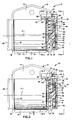
- Fig. 1 is a plan view, partially in section, of a web sensitive seat belt retractor embodying the present invention
- Fig. 2 is a view of the retractor similar to Fig. 1, illustrating parts in a different position
- Fig. 3 is a sectional view taken approximately along the line 3-3 of Fig. 1
- Fig. 4 is a side elevational view, with parts broken away, taken along the line 4-4 of Fig. 1
- Fig. 5 is a sectional view of the retractor taken approximately along the line 5-5 of Fig. 2
- Fig. 6 is a side elevational view, with parts broken away, taken along the line 6-6 of Fig. 2.
- a web sensitive seat belt retractor 10 is illustrated in Figs. 1 and 2.
- the seat belt retractor 10 includes a frame 12.
- the frame 12 has a base portion 14 and a pair of laterally spaced, generally parallel side portions 16 and 18 formed as one piece with the base portion 14.
- the retractor 10 also includes a spool 20 located between the side frame portions 16, 18.
- a shaft 22 is journalled in the side frame portions 16, 18 and supports the spool 20 for rotation about its longitudinal central axis A.
- a seat belt 24 is attached to the spool 20. Rotation of the spool 20 in a belt retraction direction winds the seat belt 24 onto the spool. Rotation of the spool 20 in a belt withdrawal direction unwinds the seat belt 24 from the spool.
- the seat belt retractor 10 includes a toothed ratchet wheel 26 which is fixed to an end portion of the spool 20.
- the ratchet wheel 26 is disposed adjacent to and inwardly of the frame side portion 16.
- a spring (not shown) is disposed in a compartment 28 outwardly of the other frame side portion 18. The spring biases the spool 20 in the belt retraction direction and thus tends to wind the seat belt 24 onto the spool 20.
- the seat belt retractor 10 includes a pawl 30 (Figs. 1 and 3) for blocking rotation of the spool 20 in the direction indicated by the arrow 27 (Figs. 2 and 3) when the belt is withdrawn, under predetermined conditions, in the direction indicated by the arrow 31.
- the pawl 30 is supported for pivotal movement about an axix B in a housing 36 attached to the frame side portion 16.
- the pawl pivots on stub shafts 25 that lie on the axis B and are journalled in openings 29 in portions 32, 34 of the housing 36.
- the pawl 30 is disposed adjacent to and extends transversely of the ratchet wheel.
- the pawl 30 is pivotable between a release position, as illustrated in Figs.
- a lock position as illustrated in Figs. 2, 5 and 6.
- the pawl 30 In the release position, the pawl 30 is disengaged from the peripheral teeth 38 on the ratchet wheel to allow rotation of the spool 20 in the belt withdrawal direction 27.
- the pawl 30 engages the teeth 38 and blocks rotation of spool 20 in the belt withdrawal direction 27.
- the ratchet teeth 38 permit rotation of the spool 20 in the direction indicated by the arrow 35 when the belt 24 is retracted onto the spool in the direction indicated by the arrow 37.
- the seat belt retractor 10 includes a U-shaped, steel leaf spring 40 (best seen in Figs. 3 to 6).
- the spring 40 is fixed at one end to a pin 42 attached to the housing 36.
- the other end of the spring 40 engages a tapered end tip 44 of the locking pawl 30.
- the spring 40 moves between a first position, illustrated in Figs. 3 and 4, and a second position, illustrated in Figs. 5 and 6. In the first position, the spring 40 biases the pawl 30 in a release direction away from the ratchet wheel 26, as indicated by the arrow 45 in Figs. 3 and 4. In the second position, the spring 40 biases the pawl 30 in a lock direction towards the ratchet wheel 26, as indicated by the arrow 47 in Figs. 5 and 6. The spring 40 moves between the first and second positions upon movement of the end tip 44 of the locking pawl 30 beyond a predetermined position.
- the predetermined position is defined by a line X interconnecting the axis B and the center of pin 42 to which the spring 40 is connected.
- the spring 40 will force the pawl to pivot further in that direction until the pawl is mechanically stopped.
- the pawl 30 is mechanically stopped from further movement when the pawl tip 44 engages the ratchet wheel 26 or when the stub shaft 25 engages the lower and arcuate surfaces, as viewed in Figs. 3 and 5, defining the openings 29 in the housing portions 32, 34.
- the spring 40 biases the pawl 30 to maintain it in that position.
- the pawl end tip 44 is moved in the lock direction from one side of the line X to the other side of the line X by a mechanism 46. This movement occurs in response to rotation of the spool 20 in the belt withdrawal direction at a rate of acceleration above a predetermined rate.
- the mechanism 46 (Figs. 4 and 6) includes a planetary gear system 48 and a connecting mechanism 50 for connecting the planetary gear system 48 to the locking pawl 30.
- the planetary gear system 48 includes a sun gear 52, a ring gear 54, and a planet gear 56.
- the sun gear 52 has external circumferential teeth 58.
- the ring gear 54 has internal circumferential teeth 60.
- the planet gear 56 has external circumferential teeth 62 intermeshing with the external teeth 58 on the sun gear 52 and the internal teeth 60 on the ring gear 54.
- the planet gear 56 moves about the central axis A of the shaft 22 and the spool 20 in response to relative rotation of the sun and ring gears 52, 54.
- the sun gear 52 is connected to the shaft 22 and thus rotates with the shaft and spool 20.
- a central stub shaft 64 is formed as one piece with the sun gear 52 and extends therefrom.
- the stub shaft 64 supports the ring gear 54 for relative rotation.
- the stub shaft 64 is received in a central hub 66 of the ring gear 54.
- the sun and ring gears 52, 54 are coaxial and rotate about the axis A.
- a circular weighted body 68 is connected to the ring gear 54 adjacent the radially extending exterior side surface of the ring gear.
- the weighted body 68 has a central opening 70 and a radially displaced smaller opening 72.
- the central hub 66 projects into the opening 70 and thus supports the weighted body 68.
- An axially extending pin 74 on the ring gear 54 projects into the radially displaced smaller opening 72 to prevent relative rotation between the ring gear and the weighted body 68.
- the ring gear 54 and weighted body 68 constitute an inertia mechanism which rotates relative to the spool 20 and sun gear 52.
- the mass of the inertia mechanism is selected so that the sun gear 52 drives the planet gear 56 which in turn drives the ring gear 54 in unison with the sun gear 52 when the spool 20 rotates in the belt withdrawal direction at a rate of acceleration less than a desired predetermined rate.
- Such relatively slow acceleration rates are ordinarily experienced when a vehicle occupant withdraws the seat belt 24 to fasten it or moves about during normal operation of the vehicle.
- the spool 20 accelerates at a rate exceeding the predetermined rate, the rotation of the inertia mechanism and thus the ring gear 54 will lag behind rotation of the sun gear 52.
- Such relatively high acceleration is experienced if a sudden withdrawal of the seat belt 24 occurs during an accident or sudden deceleration of the vehicle.
- the connecting mechanism transmits the movement of the planet gear 56 about axis A to the pawl 30.
- the spring 40 forces the pawl fully into the lock position and into engagement with the ratchet wheel 26.
- the tip 44 engages the ratchet wheel teeth 38 to prevent withdrawal of the belt 24 by blocking further rotation of the spool 20 in the clockwise direction, as viewed in Fig. 6.
- the connecting mechanism 50 includes an annular disk 76 disposed between the sun and ring gears 52, 54, on the one hand, and the housing wall 78, on the other hand, as seen in Figs. 1 and 2.
- the disk 76 is rotatably mounted on a central hub 80 integrally formed as one piece with the housing wall 78.
- a shaft portion 82 of the ring gear 52 extends coaxially through the central hub 80 and drivingly connects the shaft 22 with the ring gear.
- the circular disk 76 is rotatable relative to the hub 80, the spool 20 and the sun and ring gears 52, 54 about the axis A.
- a pin 84 is fixed to the circular disk 76 at a point located radially outward from the axis A between the sun and ring gear teeth 58, 60.
- the planet gear 56 is rotatably mounted on the pin 84.
- An actuating arm 86 is connected to and projects radially outward from the periphery of the disk 76.
- a pin 92 fixed at the outermost end of the arm 86 projects axially away from the arm. The pin 92 is received in the slotted end portion 90 of a link 88 that is connected to and pivots with the pawl 30.
- the disk 76 rotates clockwise about axis A.
- the actuating arm 86 pivots the link 88 and locking pawl 30 counterclockwise about its pivot axis B.
- the spring 40 forces the pawl to pivot further in a counterclockwise direction about axis B and into its lock position.
- the pawl 30 remains in engagement with the ratchet wheel teeth 38 while tension remains on the seat belt 24 due to the force of the occupant's body movement.
- the retraction spring in compartment 28 rotates the spool 20 in the belt retraction direction.
- the pawl 30 is biased by the spring 40 to the lock position, thereby still preventing withdrawal of the seat belt 24.
- the seat belt retractor 10 further includes an arm 94 (Figs. 1, 2, 3 and 4) connected to and pivotable with the locking pawl 30 for sensing the amount of the belt 24 which is wound onto the spool 20.
- the arm 94 overlies the edge of the belt 24 to engage the belt and moves radially outwardly, as the amount of belt wound onto the spool increases. Movement of the arm 94 also pivots the pawl 30 when a predetermined amount of belt 24 rewinds onto the spool 20.
- the locking pawl 30 is pivoted by the arm 94 clockwise, as viewed in Fig. 4, from the lock position towards the release position. When the tip 44 of the pawl 30 moves back past the predetermined position defined by the line X, the spring 40 forces the pawl 30 to pivot further clockwise, as viewed in Fig. 6, to the release position.
- the sun, ring and planet gears 52, 54, 56 and the disk 76 may be made of metal or plastic. If the ring gear 54 is made of plastic, the weighted body 68 will. preferably be made of metal to add mass to the ring gear and thus provide the desired mass.
Landscapes
- Engineering & Computer Science (AREA)
- Mechanical Engineering (AREA)
- Automotive Seat Belt Assembly (AREA)
Applications Claiming Priority (2)
| Application Number | Priority Date | Filing Date | Title |
|---|---|---|---|
| US933385 | 1986-11-21 | ||
| US06/933,385 US4768733A (en) | 1986-11-21 | 1986-11-21 | Seat belt retractor |
Publications (2)
| Publication Number | Publication Date |
|---|---|
| EP0269909A1 EP0269909A1 (en) | 1988-06-08 |
| EP0269909B1 true EP0269909B1 (en) | 1991-07-03 |
Family
ID=25463839
Family Applications (1)
| Application Number | Title | Priority Date | Filing Date |
|---|---|---|---|
| EP87116402A Expired EP0269909B1 (en) | 1986-11-21 | 1987-11-06 | Seat belt retractor |
Country Status (5)
| Country | Link |
|---|---|
| US (1) | US4768733A (ja) |
| EP (1) | EP0269909B1 (ja) |
| JP (1) | JPH0780441B2 (ja) |
| BR (1) | BR8706272A (ja) |
| DE (1) | DE3771180D1 (ja) |
Families Citing this family (11)
| Publication number | Priority date | Publication date | Assignee | Title |
|---|---|---|---|---|
| US5080299A (en) * | 1990-11-09 | 1992-01-14 | Trw Vehicle Safety Systems Ltd. | Seat belt retractor |
| WO1995019203A1 (en) * | 1994-01-13 | 1995-07-20 | Barrow Hepburn Sala Limited | Speed responsive coupling device especially for fall arrest apparatus |
| US5535959A (en) * | 1995-02-21 | 1996-07-16 | Trw Vehicle Safety Systems Inc. | Tension reducing retractor with reduced velocity ratchet |
| GB2310786B (en) * | 1996-03-05 | 2000-06-14 | Alliedsignal Ltd | Retractor locking mechanism |
| KR100901415B1 (ko) * | 2008-01-28 | 2009-06-05 | 현대자동차주식회사 | 시트벨트 리트랙터의 로킹유닛 |
| JP2009262632A (ja) * | 2008-04-22 | 2009-11-12 | Tokai Rika Co Ltd | ウエビング巻取装置 |
| US8575872B2 (en) | 2010-02-23 | 2013-11-05 | Homerun Holdings Corporation | High efficiency roller shade and method for setting artificial stops |
| US8659246B2 (en) | 2010-02-23 | 2014-02-25 | Homerun Holdings Corporation | High efficiency roller shade |
| US9194179B2 (en) | 2010-02-23 | 2015-11-24 | Qmotion Incorporated | Motorized shade with the transmission wire passing through the support shaft |
| US9249623B2 (en) | 2010-02-23 | 2016-02-02 | Qmotion Incorporated | Low-power architectural covering |
| US8739854B2 (en) * | 2012-07-02 | 2014-06-03 | Qmotion Incorporated | Pre-assembled and pre-tensioned shade with indexing gear tensioner |
Family Cites Families (15)
| Publication number | Priority date | Publication date | Assignee | Title |
|---|---|---|---|---|
| US2953315A (en) * | 1957-02-01 | 1960-09-20 | Aerotec Ind Inc | Inertia reel |
| GB860980A (en) * | 1959-04-15 | 1961-02-15 | American Seating Co | Improvements relating to reels and safety devices incorporating such reels |
| US3206137A (en) * | 1963-12-31 | 1965-09-14 | Snyderman Ruben | Web handling apparatus |
| US3510085A (en) * | 1967-07-31 | 1970-05-05 | Robbins Seat Belt Co | Emergency locking retractor with disabling means |
| US3482799A (en) * | 1968-04-09 | 1969-12-09 | Pacific Scientific Co | Safety harness device |
| US3604655A (en) * | 1969-06-11 | 1971-09-14 | Allied Chem | Inertia retractor |
| JPS5326015B2 (ja) * | 1972-11-18 | 1978-07-31 | ||
| JPS5341411B2 (ja) * | 1972-12-11 | 1978-11-02 | ||
| US3841581A (en) * | 1973-05-21 | 1974-10-15 | Gen Motors Corp | Locking mechanism for a vehicle body restraint belt retractor |
| US3897913A (en) * | 1974-05-28 | 1975-08-05 | Gen Motors Corp | Locking mechanism for a vehicle restraint belt retractor |
| US4293105A (en) * | 1976-12-23 | 1981-10-06 | Allied Chemical Corporation | Bi-level web sensitive retractor |
| US4427164A (en) * | 1982-06-21 | 1984-01-24 | The Firestone Tire & Rubber Company | Cinch lock for safety belt retractors |
| US4573646A (en) * | 1984-04-23 | 1986-03-04 | Trw Automotive Products Inc. | Mode selection retractor |
| US4566649A (en) * | 1984-06-25 | 1986-01-28 | Irvin Industries Inc. | Conversion control for combination VSI and ALR retractor |
| US4691875A (en) * | 1985-11-13 | 1987-09-08 | Trw Automotive Products Inc. | Planetary inertial seat belt retractor |
-
1986
- 1986-11-21 US US06/933,385 patent/US4768733A/en not_active Expired - Lifetime
-
1987
- 1987-11-06 EP EP87116402A patent/EP0269909B1/en not_active Expired
- 1987-11-06 DE DE8787116402T patent/DE3771180D1/de not_active Expired - Lifetime
- 1987-11-20 BR BR8706272A patent/BR8706272A/pt unknown
- 1987-11-21 JP JP62294987A patent/JPH0780441B2/ja not_active Expired - Fee Related
Also Published As
| Publication number | Publication date |
|---|---|
| BR8706272A (pt) | 1988-06-28 |
| DE3771180D1 (de) | 1991-08-08 |
| US4768733A (en) | 1988-09-06 |
| EP0269909A1 (en) | 1988-06-08 |
| JPS63199152A (ja) | 1988-08-17 |
| JPH0780441B2 (ja) | 1995-08-30 |
Similar Documents
| Publication | Publication Date | Title |
|---|---|---|
| US4948066A (en) | Retractor for seat belts | |
| EP1634781B1 (en) | Seat belt retractor | |
| US4811912A (en) | Emergency locking seat belt retractor with automatic locking mechanism | |
| EP1062122B1 (en) | Energy management safety belt retractor | |
| US5934596A (en) | Automatic locking retractor with timing clutch mechanism | |
| EP0269909B1 (en) | Seat belt retractor | |
| US3862726A (en) | Safety belt device | |
| GB2123271A (en) | Seat belt retractor | |
| EP1488968B1 (en) | Seat belt retractor | |
| US3941330A (en) | Safety belt retractor | |
| US5257754A (en) | Retractor | |
| US4896844A (en) | Dual spool retractor with comfort limiting mechanism | |
| KR100248839B1 (ko) | 시트벨트용 리트랙터 | |
| US4327882A (en) | Seat belt retractor with manual lock up | |
| EP0273584B1 (en) | Vehicle seat belt retractor with latching inhibition | |
| GB1560001A (en) | Device for applying a force to a rotable shaft | |
| US4293105A (en) | Bi-level web sensitive retractor | |
| US4691875A (en) | Planetary inertial seat belt retractor | |
| US5624087A (en) | Seat belt retractor with cinch mechanism | |
| US4840324A (en) | Seat belt retractor having a comfort mechanism with full memory and slack set | |
| US5169085A (en) | Safety belt retractor with a vehicle-sensitive and webbing-sensitive blocking mechanism | |
| CA1292971C (en) | Seat belt retractor | |
| US6206316B1 (en) | Belt retractor with force limitation | |
| JPH0347007Y2 (ja) | ||
| US4082236A (en) | Free pull web sensitive retractor |
Legal Events
| Date | Code | Title | Description |
|---|---|---|---|
| PUAI | Public reference made under article 153(3) epc to a published international application that has entered the european phase |
Free format text: ORIGINAL CODE: 0009012 |
|
| AK | Designated contracting states |
Kind code of ref document: A1 Designated state(s): DE FR GB IT SE |
|
| RAP1 | Party data changed (applicant data changed or rights of an application transferred) |
Owner name: TRW VEHICLE SAFETY SYSTEMS INC. |
|
| 17P | Request for examination filed |
Effective date: 19881111 |
|
| 17Q | First examination report despatched |
Effective date: 19891124 |
|
| GRAA | (expected) grant |
Free format text: ORIGINAL CODE: 0009210 |
|
| AK | Designated contracting states |
Kind code of ref document: B1 Designated state(s): DE FR GB IT SE |
|
| REF | Corresponds to: |
Ref document number: 3771180 Country of ref document: DE Date of ref document: 19910808 |
|
| ITF | It: translation for a ep patent filed |
Owner name: DR. ING. A. RACHELI & C. |
|
| ET | Fr: translation filed | ||
| PGFP | Annual fee paid to national office [announced via postgrant information from national office to epo] |
Ref country code: GB Payment date: 19911017 Year of fee payment: 5 |
|
| PGFP | Annual fee paid to national office [announced via postgrant information from national office to epo] |
Ref country code: SE Payment date: 19911022 Year of fee payment: 5 |
|
| PGFP | Annual fee paid to national office [announced via postgrant information from national office to epo] |
Ref country code: FR Payment date: 19911120 Year of fee payment: 5 |
|
| PLBE | No opposition filed within time limit |
Free format text: ORIGINAL CODE: 0009261 |
|
| STAA | Information on the status of an ep patent application or granted ep patent |
Free format text: STATUS: NO OPPOSITION FILED WITHIN TIME LIMIT |
|
| 26N | No opposition filed | ||
| PG25 | Lapsed in a contracting state [announced via postgrant information from national office to epo] |
Ref country code: GB Effective date: 19921106 |
|
| PG25 | Lapsed in a contracting state [announced via postgrant information from national office to epo] |
Ref country code: SE Effective date: 19921107 |
|
| GBPC | Gb: european patent ceased through non-payment of renewal fee |
Effective date: 19921106 |
|
| PG25 | Lapsed in a contracting state [announced via postgrant information from national office to epo] |
Ref country code: FR Effective date: 19930730 |
|
| EUG | Se: european patent has lapsed |
Ref document number: 87116402.6 Effective date: 19930610 |
|
| PGFP | Annual fee paid to national office [announced via postgrant information from national office to epo] |
Ref country code: DE Payment date: 19951129 Year of fee payment: 9 |
|
| PG25 | Lapsed in a contracting state [announced via postgrant information from national office to epo] |
Ref country code: DE Effective date: 19970801 |
|
| PG25 | Lapsed in a contracting state [announced via postgrant information from national office to epo] |
Ref country code: IT Free format text: LAPSE BECAUSE OF NON-PAYMENT OF DUE FEES;WARNING: LAPSES OF ITALIAN PATENTS WITH EFFECTIVE DATE BEFORE 2007 MAY HAVE OCCURRED AT ANY TIME BEFORE 2007. THE CORRECT EFFECTIVE DATE MAY BE DIFFERENT FROM THE ONE RECORDED. Effective date: 20051106 |