EP0269868B1 - lens with improved flat field characteristics - Google Patents
lens with improved flat field characteristics Download PDFInfo
- Publication number
- EP0269868B1 EP0269868B1 EP87115921A EP87115921A EP0269868B1 EP 0269868 B1 EP0269868 B1 EP 0269868B1 EP 87115921 A EP87115921 A EP 87115921A EP 87115921 A EP87115921 A EP 87115921A EP 0269868 B1 EP0269868 B1 EP 0269868B1
- Authority
- EP
- European Patent Office
- Prior art keywords
- lens
- order
- field
- shaped
- image plane
- Prior art date
- Legal status (The legal status is an assumption and is not a legal conclusion. Google has not performed a legal analysis and makes no representation as to the accuracy of the status listed.)
- Expired - Lifetime
Links
Images




Classifications
-
- G—PHYSICS
- G02—OPTICS
- G02B—OPTICAL ELEMENTS, SYSTEMS OR APPARATUS
- G02B3/00—Simple or compound lenses
-
- G—PHYSICS
- G02—OPTICS
- G02B—OPTICAL ELEMENTS, SYSTEMS OR APPARATUS
- G02B13/00—Optical objectives specially designed for the purposes specified below
- G02B13/04—Reversed telephoto objectives
-
- G—PHYSICS
- G02—OPTICS
- G02B—OPTICAL ELEMENTS, SYSTEMS OR APPARATUS
- G02B27/00—Optical systems or apparatus not provided for by any of the groups G02B1/00 - G02B26/00, G02B30/00
- G02B27/0025—Optical systems or apparatus not provided for by any of the groups G02B1/00 - G02B26/00, G02B30/00 for optical correction, e.g. distorsion, aberration
Definitions
- the invention relates to a lens assembly including a field flattener as a last subassembly before the image plane and a method of controlling third and fifth order Petzval curvature and third and fifth order distortion in order to achieve best overall field characteristics in a lens system extending along an optical his from an object space to an image plane.
- Lenses usable in step and repeat microlithography must have high numerical apertures and must have fields as flat as possible in order to reproduce the reticle pattern accurately onto the surface of the wafer.
- the third order Petzval curvature is left partly under-corrected. That is, it is curved inward toward the lens so that at some point in the field the third order Petzval just balances the fifth order Petzval.
- the fifth order Petzval is usually positive, or over corrected, and curves away from the lens.
- the curvature of field is zero and the position of best focus corresponds to the paraxial focus.
- the position of best focus includes factors other than Petzval curvature.
- Petzval curvature has a strong influence and results in a field which, at low values of image height curves inward but, at large values of image height, curves outward from the lens.
- a single strong field lens may be used to correct the third order Petzval curvature.
- no amount of bending of the strong field lens will correct the fifth order Petzval and, in fact, only adds additional over correction.
- An example of a field flattener employed to correct third order field curvature is disclosed in U. S. Patent 2,846,923 of A. W. Tronnier. In the system disclosed in this patent, third and fifth order distortion remained when such a field flattener was employed.
- the lens assembly according to the present invention is characterized in that the field flattener comprises a relatively strong positive first element nearest the image plane; and a relatively strong second element preceding the first element; said second element having surfaces which are shaped so as to over-correct the third order Petzval curvature and said first element having surfaces which are shaped so as to substantially offset the over correction introduced by the second element.
- the method according to the present invention is characterized by positioning a relatively strong positive first lens element along said optical axis nearest the image plane; and positioning a relatively strong negative second lens element along said optical axis preceding the first lens element; wherein the second lens element is provided with surfaces which are shaped so as to over correct the third order Petzval curvature and said second lens element is provided with surfaces which are shaped so as to substantially offset the over correction introduced by the second element.
- the invention will first be described in connection with its use with a singlet.
- a singlet 10 and a compound field flattener L F comprising negative element 12 and positive element 14.
- the prescription of the lens assembly of FIG. 1 is given in Table I (dimensions in mm).
- the following table gives the power of each surface of the singlet 10 and the compound field flattener L F .
- the second and third surfaces are the positive singlet and each surface has a power +.005 for a total power of +.010.
- the compound field flattener L F is made up of surfaces 4, 5, 6, and 7 which have a total power of -.010 which just balances the power of the singlet and results in a fully corrected third order Petzval curvature.
- Negative element surfaces 4 and 5 over correct the third order Petzval curvature by only 17.5% in that its power is -.01175 rather than -.0100.
- the negative element 12 of the field flatterer L F over corrects the curvature of field by only a slight amount.
- the positive element 14 adds back the 17.5% over correction.
- the following table gives the third order surface by surface contributions of the FIG. 1 lens assembly. Examination of the table above indicates that surface 4, the first surface of the field flattener L F provides most of the third order field flattening.
- Table IV gives the fifth order surface by surface contribution of the lens assembly of FIG. 1. Inspection of Table IV will indicate that the correction of the fifth order Petzval curvature is provided by the meniscus positive element 14 of the field flattener L F .
- the third and fifth order aberrations of the lens of FIG. 1 is given in the following table.
- the field flattener of this invention may also be employed with a more complex lens assembly such as illustrated in FIG. 2.
- the prescription is given in Table VI.
- Table VII gives the third and fifth order aberrations when traced from the object to the image.
- FIG. 3 is the plot of best focus versus image height of the lens of FIG. 2. It will be noted that, with the fifth order Petzval curvature corrected, the seventh order Petzval, which is negative, becomes dominant at the edge of the field. As a result, the best focus curves back in towards the lens, resulting in a third cross-over point. Accordingly, there is achieved a much flatter field and a wider field of good correction than has heretofore been achievable.
- the foregoing refractive design also has the same magnification, NA, track length, and corrected wavelength as the design shown in FIG. 2.
- the third and fifth order aberrations, with the fifth order Petzval limited but not zero, are given in Table IX.
Landscapes
- Physics & Mathematics (AREA)
- General Physics & Mathematics (AREA)
- Optics & Photonics (AREA)
- Lenses (AREA)
Description
- The invention relates to a lens assembly including a field flattener as a last subassembly before the image plane and a method of controlling third and fifth order Petzval curvature and third and fifth order distortion in order to achieve best overall field characteristics in a lens system extending along an optical his from an object space to an image plane.
- Lenses usable in step and repeat microlithography must have high numerical apertures and must have fields as flat as possible in order to reproduce the reticle pattern accurately onto the surface of the wafer.
- In conventional optical designs for such applications, the third order Petzval curvature is left partly under-corrected. That is, it is curved inward toward the lens so that at some point in the field the third order Petzval just balances the fifth order Petzval. The fifth order Petzval is usually positive, or over corrected, and curves away from the lens. Thus, at the point where the third and fifth order Petzval just balance, the curvature of field is zero and the position of best focus corresponds to the paraxial focus. By choosing a different focus on axis than the best focus, a better balance can be achieved so that, at two points in the field, the position of best focus corresponds to the image plane.
- The position of best focus includes factors other than Petzval curvature. However, Petzval curvature has a strong influence and results in a field which, at low values of image height curves inward but, at large values of image height, curves outward from the lens. It has been discovered that a single strong field lens may be used to correct the third order Petzval curvature. However, it has also been determined that no amount of bending of the strong field lens will correct the fifth order Petzval and, in fact, only adds additional over correction. An example of a field flattener employed to correct third order field curvature is disclosed in U. S. Patent 2,846,923 of A. W. Tronnier. In the system disclosed in this patent, third and fifth order distortion remained when such a field flattener was employed.
- From US-A-3 497 291, a wide angle photographic or cinematographic objective is known which objective includes a front and a rear group of air-spaced lens members. In comparison with other objectives of this type, the objection of this reference is improved with respect to the correction of residual aberrations and the field curvature.
- It is the object of the present invention to provide a lens assembly in which a flat field can be achieved which assembly is improved with respect to corrections.
- The lens assembly according to the present invention is characterized in that the field flattener comprises a relatively strong positive first element nearest the image plane; and a relatively strong second element preceding the first element; said second element having surfaces which are shaped so as to over-correct the third order Petzval curvature and said first element having surfaces which are shaped so as to substantially offset the over correction introduced by the second element.
- The method according to the present invention is characterized by positioning a relatively strong positive first lens element along said optical axis nearest the image plane; and positioning a relatively strong negative second lens element along said optical axis preceding the first lens element; wherein the second lens element is provided with surfaces which are shaped so as to over correct the third order Petzval curvature and said second lens element is provided with surfaces which are shaped so as to substantially offset the over correction introduced by the second element.
- Due to the present invention, it is possible to correct both third and fifth order Petzval curvatures as well as third and fifth order distortion. The field achieved with the present invention is wider, or larger than previously possible having good correction.
-
- FIG. 1 is a lens diagram of a singlet having a field flattener in accordance with the invention;
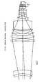
- FIG. 2 is an optical diagram of a multi-element lens having the field flattener of the invention;
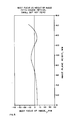
- FIG. 3 is a plot of best focus versus height of image for the lens of FIG. 2;
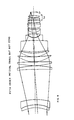
- FIG. 4 is a diagram of a modified version of the lens of FIG. 2;
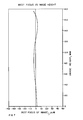
- FIG. 5 is a graph of best focus versus height of image for the lens of FIG. 4;
- FIG. 6 is a diagram of a color corrected version of the lens of this invention;
- FIG. 7 is a graph of the best focus versus height of image for the lens of FIG. 6; and
- FIG. 8 is a graph of the monochromatic and weighted polychromatic performance of the lens of FIG. 6.
- The invention will first be described in connection with its use with a singlet. With particular reference to FIG. 1, there is illustrated a
singlet 10 and a compound field flattener LF comprisingnegative element 12 andpositive element 14. The prescription of the lens assembly of FIG. 1 is given in Table I (dimensions in mm).
- The following table gives the power of each surface of the
singlet 10 and the compound field flattener LF.
The second and third surfaces are the positive singlet and each surface has a power +.005 for a total power of +.010. The compound field flattener LF is made up of surfaces 4, 5, 6, and 7 which have a total power of -.010 which just balances the power of the singlet and results in a fully corrected third order Petzval curvature. Negative element surfaces 4 and 5 over correct the third order Petzval curvature by only 17.5% in that its power is -.01175 rather than -.0100. Thus, thenegative element 12 of the field flatterer LF over corrects the curvature of field by only a slight amount. Thepositive element 14 adds back the 17.5% over correction. - The following table gives the third order surface by surface contributions of the FIG. 1 lens assembly.

Examination of the table above indicates that surface 4, the first surface of the field flattener LF provides most of the third order field flattening. - Table IV gives the fifth order surface by surface contribution of the lens assembly of FIG. 1.
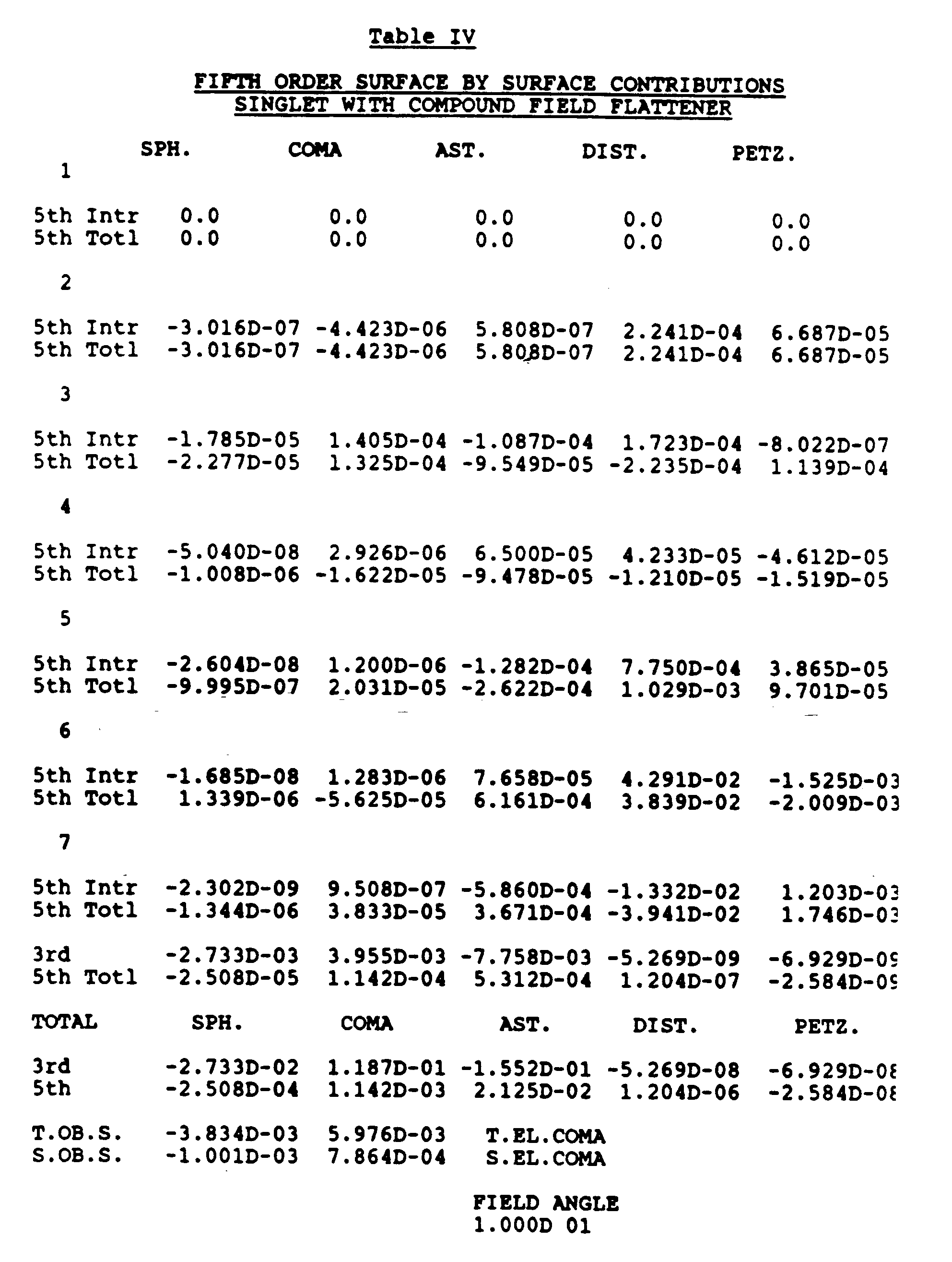
Inspection of Table IV will indicate that the correction of the fifth order Petzval curvature is provided by the meniscuspositive element 14 of the field flattener LF. - The third and fifth order aberrations of the lens of FIG. 1 is given in the following table.

- The field flattener of this invention may also be employed with a more complex lens assembly such as illustrated in FIG. 2. This is a refractive design with a magnification of -.2X, NA=.35, with a track length of 1,000 mm, and corrects at a wavelength of λ =0.4055 µm. The prescription is given in Table VI.

- Table VII gives the third and fifth order aberrations when traced from the object to the image.

- It will be noted that the fifth order Petzval curvature has been completely corrected and the third order Petzval is substantially reduced. FIG. 3 is the plot of best focus versus image height of the lens of FIG. 2. It will be noted that, with the fifth order Petzval curvature corrected, the seventh order Petzval, which is negative, becomes dominant at the edge of the field. As a result, the best focus curves back in towards the lens, resulting in a third cross-over point. Accordingly, there is achieved a much flatter field and a wider field of good correction than has heretofore been achievable.
- It is often better to control the fifth order Petzval rather than to completely correct it. This allows the focus and the 3rd, 5th, and 7th order Petzval to be balanced for best overall field characteristics. A lens assembly of such a design is illustrated in FIG. 4 and its prescription given in Table VIII below.

- The foregoing refractive design also has the same magnification, NA, track length, and corrected wavelength as the design shown in FIG. 2. The third and fifth order aberrations, with the fifth order Petzval limited but not zero, are given in Table IX.

- The resulting curve of best focus versus height of image is given in FIG. 5. It will be noted that the third cross-over is retained but that the inward curve at the edge of the field is reduced.
- By further refinement of this design a final color corrected version was obtained. The color correction is for the mercury h line with a bandwidth of λ=.4015 µm, to λ=.4095µm. This design is illustrated in FIG. 6 and its prescription is given in Table X.
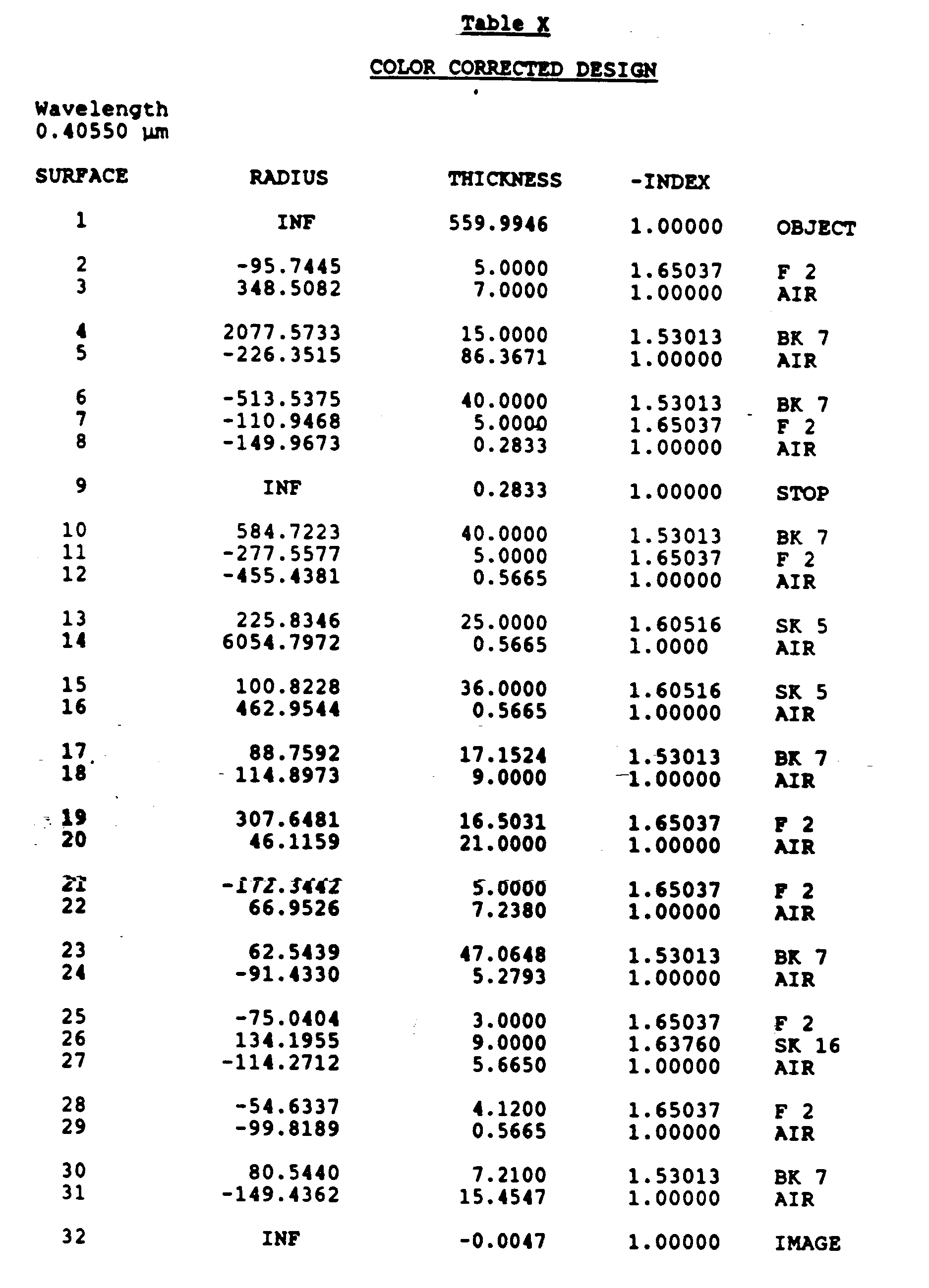
The third and fifth order aberrations are given in Table XI and its surface of best focus is given in FIG. 7. The monochromatic performance as well as the weighted polychromatic performance is given in FIG. 8.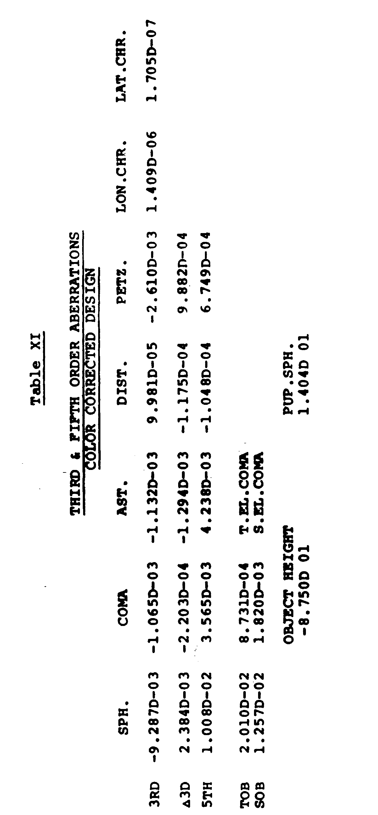
- It is believed that the many advantages of this invention will now be apparent to those skilled in the art. It will also be apparent that a number of variations and modifications may be made therein without departing from its scope. Accordingly, the foregoing description is to be construed as illustrative only, rather than limiting. This invention is limited only by the scope of the following claims.
Claims (3)
- A lens assembly including a field flattener (LF) formed of two elements as the last subassembly before the image plane (IP),
characterized in that
said field flattener comprises a relatively strong positive first element (14) nearest the image plane (IP); and a relatively strong negative second element (12) preceding the first element(14); said second element having surfaces which are shaped so as to over-correct the third order Petzval curvature and said first element having surfaces which are shaped so as to substantially offset the overcorrection introduced by the second element. - The lens assembly of Claim 1 wherein the surfaces of said first element (14) are furthermore shaped so as to substantially correct the fifth order Petzval curvature.
- A method of controlling the third and fifth order Petzval curvature and third and fifth order distortion in order to achieve best overall field characteristics in a lens system extending along an optical axis from an object space to an image plane, which method comprises: positioning a relatively strong positive field lens element along said optical axis nearest the image plane; and positioning a relatively strong negative second lens element along said optical axis preceding the first lens element; wherein said second lens element is provided with surfaces which are shaped so as to over-correct the third order Petzval curvature and said first lens element is provided with surfaces which are shaped so as to substantially offset the over-correction introduced by the second element.
Applications Claiming Priority (2)
| Application Number | Priority Date | Filing Date | Title |
|---|---|---|---|
| US06/927,215 US4772107A (en) | 1986-11-05 | 1986-11-05 | Wide angle lens with improved flat field characteristics |
| US927215 | 1992-08-10 |
Publications (2)
| Publication Number | Publication Date |
|---|---|
| EP0269868A1 EP0269868A1 (en) | 1988-06-08 |
| EP0269868B1 true EP0269868B1 (en) | 1992-07-08 |
Family
ID=25454409
Family Applications (1)
| Application Number | Title | Priority Date | Filing Date |
|---|---|---|---|
| EP87115921A Expired - Lifetime EP0269868B1 (en) | 1986-11-05 | 1987-10-29 | lens with improved flat field characteristics |
Country Status (5)
| Country | Link |
|---|---|
| US (1) | US4772107A (en) |
| EP (1) | EP0269868B1 (en) |
| JP (1) | JPS63135912A (en) |
| KR (1) | KR880006554A (en) |
| DE (1) | DE3780266D1 (en) |
Cited By (2)
| Publication number | Priority date | Publication date | Assignee | Title |
|---|---|---|---|---|
| US8908269B2 (en) | 2004-01-14 | 2014-12-09 | Carl Zeiss Smt Gmbh | Immersion catadioptric projection objective having two intermediate images |
| US8913316B2 (en) | 2004-05-17 | 2014-12-16 | Carl Zeiss Smt Gmbh | Catadioptric projection objective with intermediate images |
Families Citing this family (27)
| Publication number | Priority date | Publication date | Assignee | Title |
|---|---|---|---|---|
| US5164789A (en) * | 1990-11-09 | 1992-11-17 | Hitachi, Ltd. | Method and apparatus for measuring minute displacement by subject light diffracted and reflected from a grating to heterodyne interference |
| US5153778A (en) * | 1991-06-19 | 1992-10-06 | At&T Bell Laboratories | Powerless field-corrective lens |
| US5323263A (en) * | 1993-02-01 | 1994-06-21 | Nikon Precision Inc. | Off-axis catadioptric projection system |
| US5515207A (en) * | 1993-11-03 | 1996-05-07 | Nikon Precision Inc. | Multiple mirror catadioptric optical system |
| JP3396935B2 (en) * | 1993-11-15 | 2003-04-14 | 株式会社ニコン | Projection optical system and projection exposure apparatus |
| JP3360387B2 (en) * | 1993-11-15 | 2002-12-24 | 株式会社ニコン | Projection optical system and projection exposure apparatus |
| JPH08179204A (en) | 1994-11-10 | 1996-07-12 | Nikon Corp | Projection optical system and projection exposure apparatus |
| USRE38465E1 (en) | 1994-12-14 | 2004-03-16 | Nikon Corporation | Exposure apparatus |
| JP3500745B2 (en) * | 1994-12-14 | 2004-02-23 | 株式会社ニコン | Projection optical system, projection exposure apparatus, and projection exposure method |
| JP3454390B2 (en) * | 1995-01-06 | 2003-10-06 | 株式会社ニコン | Projection optical system, projection exposure apparatus, and projection exposure method |
| JP3819048B2 (en) * | 1995-03-15 | 2006-09-06 | 株式会社ニコン | Projection optical system, exposure apparatus including the same, and exposure method |
| JP3624973B2 (en) * | 1995-10-12 | 2005-03-02 | 株式会社ニコン | Projection optical system |
| JP3750123B2 (en) * | 1996-04-25 | 2006-03-01 | 株式会社ニコン | Projection optical system |
| US5808814A (en) * | 1996-07-18 | 1998-09-15 | Nikon Corporation | Short wavelength projection optical system |
| JP3864399B2 (en) * | 1996-08-08 | 2006-12-27 | 株式会社ニコン | Projection exposure apparatus, projection optical system used in the projection exposure apparatus, and device manufacturing method |
| US5852490A (en) * | 1996-09-30 | 1998-12-22 | Nikon Corporation | Projection exposure method and apparatus |
| JP3757536B2 (en) * | 1996-10-01 | 2006-03-22 | 株式会社ニコン | Projection optical system, exposure apparatus including the same, and device manufacturing method |
| JPH116957A (en) * | 1997-04-25 | 1999-01-12 | Nikon Corp | Projection optical system, projection exposure apparatus, and projection exposure method |
| US6084706A (en) * | 1997-07-09 | 2000-07-04 | Etec Systems, Inc. | High efficiency laser pattern generator |
| JP3925576B2 (en) | 1997-07-24 | 2007-06-06 | 株式会社ニコン | Projection optical system, exposure apparatus including the optical system, and device manufacturing method using the apparatus |
| US6700645B1 (en) | 1998-01-22 | 2004-03-02 | Nikon Corporation | Projection optical system and exposure apparatus and method |
| JPH11214293A (en) | 1998-01-22 | 1999-08-06 | Nikon Corp | Projection optical system, exposure apparatus having the optical system, and device manufacturing method |
| WO2002080521A2 (en) * | 2001-03-30 | 2002-10-10 | Digeo, Inc. | System and method for a software steerable web camera with multiple image subset capture |
| US20020141657A1 (en) | 2001-03-30 | 2002-10-03 | Robert Novak | System and method for a software steerable web Camera |
| ATE315794T1 (en) | 2002-03-25 | 2006-02-15 | Konishiroku Photo Ind | THREE LENS LENS |
| US20080151365A1 (en) | 2004-01-14 | 2008-06-26 | Carl Zeiss Smt Ag | Catadioptric projection objective |
| WO2009035072A1 (en) * | 2007-09-13 | 2009-03-19 | Nikon Corporation | Immersion microscope objective lens |
Family Cites Families (7)
| Publication number | Priority date | Publication date | Assignee | Title |
|---|---|---|---|---|
| US2846923A (en) * | 1957-02-25 | 1958-08-12 | Farrand Optical Co Inc | High speed objective lens with anastigmatically flattened field |
| DE1497588A1 (en) * | 1966-02-26 | 1969-04-30 | Schneider Co Optische Werke | Photographic or cinematographic lens with a large field of view |
| JPS5328089B2 (en) * | 1973-05-01 | 1978-08-12 | ||
| US4001766A (en) * | 1975-02-26 | 1977-01-04 | Westinghouse Electric Corporation | Acoustic lens system |
| US4256374A (en) * | 1979-04-02 | 1981-03-17 | Mca Discovision, Inc. | Write and read objective lens for high density storage |
| CA1127894A (en) * | 1979-05-16 | 1982-07-20 | Philip J. Rogers | Transfer lens for optical image display system |
| US4411499A (en) * | 1980-11-07 | 1983-10-25 | Honeywell Inc. | Compact optical system |
-
1986
- 1986-11-05 US US06/927,215 patent/US4772107A/en not_active Expired - Fee Related
-
1987
- 1987-10-29 EP EP87115921A patent/EP0269868B1/en not_active Expired - Lifetime
- 1987-10-29 DE DE8787115921T patent/DE3780266D1/en not_active Expired - Lifetime
- 1987-11-04 KR KR870012379A patent/KR880006554A/en not_active Withdrawn
- 1987-11-05 JP JP62278416A patent/JPS63135912A/en active Pending
Cited By (4)
| Publication number | Priority date | Publication date | Assignee | Title |
|---|---|---|---|---|
| US8908269B2 (en) | 2004-01-14 | 2014-12-09 | Carl Zeiss Smt Gmbh | Immersion catadioptric projection objective having two intermediate images |
| US8913316B2 (en) | 2004-05-17 | 2014-12-16 | Carl Zeiss Smt Gmbh | Catadioptric projection objective with intermediate images |
| US9019596B2 (en) | 2004-05-17 | 2015-04-28 | Carl Zeiss Smt Gmbh | Catadioptric projection objective with intermediate images |
| US9134618B2 (en) | 2004-05-17 | 2015-09-15 | Carl Zeiss Smt Gmbh | Catadioptric projection objective with intermediate images |
Also Published As
| Publication number | Publication date |
|---|---|
| EP0269868A1 (en) | 1988-06-08 |
| US4772107A (en) | 1988-09-20 |
| JPS63135912A (en) | 1988-06-08 |
| KR880006554A (en) | 1988-07-23 |
| DE3780266D1 (en) | 1992-08-13 |
Similar Documents
| Publication | Publication Date | Title |
|---|---|---|
| EP0269868A1 (en) | Lens with improved flat field characteristics | |
| JPH0933803A (en) | Image forming lens | |
| JPH07101253B2 (en) | Shooting lens using floating | |
| JPH10301021A (en) | Small-sized lens | |
| JPH0664235B2 (en) | Wide-angle lens for copying | |
| US3395962A (en) | Superachromatic objective | |
| US4257678A (en) | Wide angle photographic lens | |
| JP2000284172A (en) | Color image read lens | |
| KR100486379B1 (en) | MICROSCOPE EYEPIECE WITH 10x MAGNIFICATION | |
| US20020034018A1 (en) | Objective lens for microscope | |
| CN216351507U (en) | Microscope objective | |
| JPH0644096B2 (en) | Compact and high-performance telephoto lens | |
| JPH02300708A (en) | Zoom lens for variable magnification copying machine | |
| CN112526833B (en) | Projection imaging system for maskless lithography | |
| JP3026648B2 (en) | 1x projection lens | |
| JP2023090116A5 (en) | ||
| JP4592293B2 (en) | Variable magnification lens | |
| JPS61129613A (en) | variable focal length lens | |
| JPH02106710A (en) | Photographic optical system formed by using single lens aspherical lens | |
| JP3385337B2 (en) | Copying lens | |
| JP2000019387A (en) | Imaging lens | |
| Cao et al. | An improved prime focus corrector for f/3 true or quasi Ritchey-Chretien primaries | |
| KR100284994B1 (en) | Triplet-type objective lens | |
| RU2075771C1 (en) | Objective microlens with enlarged working distance | |
| JPS6231816A (en) | Microscope objective lens |
Legal Events
| Date | Code | Title | Description |
|---|---|---|---|
| PUAI | Public reference made under article 153(3) epc to a published international application that has entered the european phase |
Free format text: ORIGINAL CODE: 0009012 |
|
| AK | Designated contracting states |
Kind code of ref document: A1 Designated state(s): DE FR GB IT NL |
|
| 17P | Request for examination filed |
Effective date: 19881208 |
|
| 17Q | First examination report despatched |
Effective date: 19901221 |
|
| RAP1 | Party data changed (applicant data changed or rights of an application transferred) |
Owner name: SVG LITHOGRAPHY SYSTEMS, INC. |
|
| GRAA | (expected) grant |
Free format text: ORIGINAL CODE: 0009210 |
|
| ITF | It: translation for a ep patent filed | ||
| AK | Designated contracting states |
Kind code of ref document: B1 Designated state(s): DE FR GB IT NL |
|
| PG25 | Lapsed in a contracting state [announced via postgrant information from national office to epo] |
Ref country code: NL Effective date: 19920708 Ref country code: FR Effective date: 19920708 Ref country code: DE Effective date: 19920708 |
|
| REF | Corresponds to: |
Ref document number: 3780266 Country of ref document: DE Date of ref document: 19920813 |
|
| PG25 | Lapsed in a contracting state [announced via postgrant information from national office to epo] |
Ref country code: GB Effective date: 19921029 |
|
| EN | Fr: translation not filed | ||
| NLV1 | Nl: lapsed or annulled due to failure to fulfill the requirements of art. 29p and 29m of the patents act | ||
| PLBE | No opposition filed within time limit |
Free format text: ORIGINAL CODE: 0009261 |
|
| STAA | Information on the status of an ep patent application or granted ep patent |
Free format text: STATUS: NO OPPOSITION FILED WITHIN TIME LIMIT |
|
| GBPC | Gb: european patent ceased through non-payment of renewal fee |
Effective date: 19921029 |
|
| 26N | No opposition filed | ||
| PG25 | Lapsed in a contracting state [announced via postgrant information from national office to epo] |
Ref country code: IT Free format text: LAPSE BECAUSE OF NON-PAYMENT OF DUE FEES;WARNING: LAPSES OF ITALIAN PATENTS WITH EFFECTIVE DATE BEFORE 2007 MAY HAVE OCCURRED AT ANY TIME BEFORE 2007. THE CORRECT EFFECTIVE DATE MAY BE DIFFERENT FROM THE ONE RECORDED. Effective date: 20051029 |