EP0268845B1 - Membrankondensator zur Messung sehr geringer pneumatischer Wechseldrücke - Google Patents
Membrankondensator zur Messung sehr geringer pneumatischer Wechseldrücke Download PDFInfo
- Publication number
- EP0268845B1 EP0268845B1 EP87115653A EP87115653A EP0268845B1 EP 0268845 B1 EP0268845 B1 EP 0268845B1 EP 87115653 A EP87115653 A EP 87115653A EP 87115653 A EP87115653 A EP 87115653A EP 0268845 B1 EP0268845 B1 EP 0268845B1
- Authority
- EP
- European Patent Office
- Prior art keywords
- base plate
- membrane
- ceramics base
- annular mandrel
- fixed electrode
- Prior art date
- Legal status (The legal status is an assumption and is not a legal conclusion. Google has not performed a legal analysis and makes no representation as to the accuracy of the status listed.)
- Expired - Lifetime
Links
- 239000012528 membrane Substances 0.000 claims description 32
- 239000000919 ceramic Substances 0.000 claims description 21
- 239000002184 metal Substances 0.000 claims description 21
- 229910052751 metal Inorganic materials 0.000 claims description 21
- 239000003990 capacitor Substances 0.000 claims description 15
- 238000005516 engineering process Methods 0.000 claims description 5
- 239000000463 material Substances 0.000 claims description 4
- 238000000034 method Methods 0.000 claims description 3
- 238000004868 gas analysis Methods 0.000 claims description 2
- 239000010409 thin film Substances 0.000 claims description 2
- 239000011248 coating agent Substances 0.000 claims 2
- 238000000576 coating method Methods 0.000 claims 2
- 238000001311 chemical methods and process Methods 0.000 claims 1
- 238000007747 plating Methods 0.000 claims 1
- 239000007789 gas Substances 0.000 description 3
- 239000010408 film Substances 0.000 description 2
- 238000004519 manufacturing process Methods 0.000 description 2
- 239000004020 conductor Substances 0.000 description 1
- 239000011521 glass Substances 0.000 description 1
- 150000002739 metals Chemical class 0.000 description 1
- 239000000126 substance Substances 0.000 description 1
Images
Classifications
-
- G—PHYSICS
- G01—MEASURING; TESTING
- G01L—MEASURING FORCE, STRESS, TORQUE, WORK, MECHANICAL POWER, MECHANICAL EFFICIENCY, OR FLUID PRESSURE
- G01L9/00—Measuring steady of quasi-steady pressure of fluid or fluent solid material by electric or magnetic pressure-sensitive elements; Transmitting or indicating the displacement of mechanical pressure-sensitive elements, used to measure the steady or quasi-steady pressure of a fluid or fluent solid material, by electric or magnetic means
- G01L9/0041—Transmitting or indicating the displacement of flexible diaphragms
- G01L9/0072—Transmitting or indicating the displacement of flexible diaphragms using variations in capacitance
Definitions
- the invention relates to a membrane capacitor for measuring very low pneumatic alternating pressures, in particular in gas analysis devices with optopneumatic detectors according to the preamble of claim 1.
- Such a membrane capacitor is known from DE-GM 79 22 944.
- This membrane capacitor has a fixed electrode made of metal and an annular mandrel with a foot part arranged around it at a distance.
- the fixed electrode and the base part of the annular mandrel are attached to a ceramic plate.
- the membrane of the capacitor is fixed in a socket which consists of two ring-shaped parts, a flat ring and another ring, the cross-sectional area of which is of rectangular shape.
- the ring-shaped holder part has an internal fine thread with which the holder is screwed onto the mandrel provided with a corresponding counter thread.
- the membrane is tensioned by twisting the socket for the membrane relative to the annular mandrel.
- the height of the annular mandrel relative to the fixed electrode determines the distance between the membrane and the fixed electrode.
- Such membrane capacitors are very expensive to manufacture. There are also large gas-wetted metal surfaces that require chemically resistant metals in the case of aggressive gases
- the invention has for its object to provide a membrane capacitor of the type mentioned, which is easier to manufacture and in which the gas-contacted metal surfaces are reduced to a minimum.
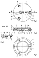
- the ceramic base plate 1 has a concentrically arranged cylindrical elevation 1a.
- an annular mandrel 2 is applied by material application.
- a circular metal layer serving as a fixed electrode 3 is applied to the cylindrical elevation 1a of the ceramic plate 1.
- a metal membrane 4 is held in a manner known per se between two rings 5, 6, which form a clamping ring arrangement.
- the metal membrane 4 lies on the annular mandrel 2.
- Screws 7, 8, 9 connect the clamping ring arrangement to the ceramic base plate 1.
- the tension of the metal membrane 4 can be adjusted using the screws 7, 8, 9.
- a plate spring 10 which is provided with holes according to the arrangement of the screws 7, 8, 9 serves to secure the screws against unintentional loosening and absorbs the forces generated by the weight of the rings 5, 6.
- the ceramic base plate 1 has an opening 1b, the wall surface of which is provided with a metal layer 11. The opening 1b establishes the gas connection to the interior of the membrane capacitor.
- the fixed electrode 3 is electrically connected to a first contact tap 12 via the metal layer 11.
- the electrical connection of the metal membrane 4 to a further contact tap 14 takes place via the electrically conductive rings 5, 6 as well as via the screw 7 and a conductor track 13.
- FIG. 3 shows a detail of FIG. 2 in an enlarged view.
- the annular mandrel 2 consists of two layers 2a and 2b which are applied in the outer region of the cylindrical elevation 1a of the ceramic base plate 1.
- the layers 2a and 2b are printed on the ceramic base plate 1 in a manner known per se from glass or another material using thick-film technology.
- the lower layer 2a is designed as a wide ring, while the top layer 2b is designed as a narrow ring with a spherical surface in the outer region of the lower layer 2a.
- the total height of the annular mandrel 2 determines the distance between the fixed electrode 3 and the metal membrane 4 of the membrane capacitor and is in the order of 40 to 150 ⁇ m depending on the application.
- the lower layer 2a can also be applied in several work steps, ie in several layers.
- the arrangement of the uppermost layer 2b in the outer region of the underlying layer prevents the metal membrane 4 from being clamped on the outer edge of the cylindrical elevation 1a the ceramic base plate 1 comes to rest.
- the spherical surface of the uppermost layer 2b facilitates tensioning of the metal membrane 4 and improves the seal between the annular mandrel 2 and the metal membrane 4.
- FIG. 4 shows a top view of the membrane capacitor described above with reference to FIGS. 1 to 3.
- the metal membrane 4 and the upper ring 5 clamping ring arrangement cover most of the ceramic base plate 1.
- the surface of the cylindrical elevation 1a has a planicity of less than 3 ⁇ m over the entire cross section.
- the fixed electrode 3 consists of a metal resistant to aggressive gases, the z. B. is applied in thin film technology. Although other known processes, such as thick-film technology or chemical or galvanic processes, can also be used for this.
- the thickness of the fixed electrode 3 is less than 3 microns.
- the outer diameter of the annular mandrel 2 is between 10 and 20 mm.
Landscapes
- Physics & Mathematics (AREA)
- General Physics & Mathematics (AREA)
- Measuring Fluid Pressure (AREA)
- Fixed Capacitors And Capacitor Manufacturing Machines (AREA)
- Investigating Or Analyzing Materials By The Use Of Electric Means (AREA)
Applications Claiming Priority (2)
| Application Number | Priority Date | Filing Date | Title |
|---|---|---|---|
| DE19863640718 DE3640718A1 (de) | 1986-11-28 | 1986-11-28 | Membrankondensator zur messung sehr geringer pneumatischer wechseldruecke |
| DE3640718 | 1986-11-28 |
Publications (3)
| Publication Number | Publication Date |
|---|---|
| EP0268845A2 EP0268845A2 (de) | 1988-06-01 |
| EP0268845A3 EP0268845A3 (en) | 1990-07-04 |
| EP0268845B1 true EP0268845B1 (de) | 1992-04-15 |
Family
ID=6315017
Family Applications (1)
| Application Number | Title | Priority Date | Filing Date |
|---|---|---|---|
| EP87115653A Expired - Lifetime EP0268845B1 (de) | 1986-11-28 | 1987-10-26 | Membrankondensator zur Messung sehr geringer pneumatischer Wechseldrücke |
Country Status (2)
| Country | Link |
|---|---|
| EP (1) | EP0268845B1 (enExample) |
| DE (2) | DE3640718A1 (enExample) |
Family Cites Families (6)
| Publication number | Priority date | Publication date | Assignee | Title |
|---|---|---|---|---|
| US2667786A (en) * | 1950-02-11 | 1954-02-02 | Cons Eng Corp | Capacitor pressure gauge |
| US2808545A (en) * | 1955-01-24 | 1957-10-01 | Walter J Hirtreiter | Pressure pick-up-differential-type acceleration-free |
| US4168517A (en) * | 1977-11-10 | 1979-09-18 | Lee Shih Y | Capacitive pressure transducer |
| DE7922944U1 (de) * | 1979-08-10 | 1979-11-22 | Hartmann & Braun Ag, 6000 Frankfurt | Membrankondensator zur messung sehr geringer pneumatischer wechseldruecke in gasanalysegeraeten |
| DE3404262A1 (de) * | 1983-03-09 | 1984-09-13 | Fuji Electric Co., Ltd., Kawasaki | Kapazitiver messfuehler |
| GB2162319B (en) * | 1984-06-06 | 1987-08-19 | Furness Controls Ltd | Pressure sensitive capacitor |
-
1986
- 1986-11-28 DE DE19863640718 patent/DE3640718A1/de active Granted
-
1987
- 1987-10-26 EP EP87115653A patent/EP0268845B1/de not_active Expired - Lifetime
- 1987-10-26 DE DE8787115653T patent/DE3778310D1/de not_active Expired - Fee Related
Also Published As
| Publication number | Publication date |
|---|---|
| DE3778310D1 (de) | 1992-05-21 |
| EP0268845A3 (en) | 1990-07-04 |
| DE3640718C2 (enExample) | 1989-05-24 |
| DE3640718A1 (de) | 1988-06-09 |
| EP0268845A2 (de) | 1988-06-01 |
Similar Documents
| Publication | Publication Date | Title |
|---|---|---|
| DE2709945C2 (de) | Kapazitiver Druckwandler | |
| DE3142387C2 (enExample) | ||
| DE3883067T2 (de) | Kapazitives Manometer zur Absolutdruckmessung. | |
| DE69907423T2 (de) | Druckdifferenzwandler | |
| EP1384980A1 (de) | Feuchtigkeitsschutz für einen elektromechanischen Wandler | |
| EP1560011B1 (de) | Dehnmessstreifen mit Feuchtigkeitsschutz durch inhomogene anorganische Schicht auf glättender Polymerschicht (ORMOCER) und Schlitzanordnung | |
| EP0674164B1 (de) | Kapazitiver Drucksensor bzw. kapazitiver Differenzdrucksensor | |
| EP1236038A1 (de) | Kapazitiver sensor | |
| DE2411212A1 (de) | Druckmesseinrichtung | |
| DE3629628A1 (de) | Kapazitiver hochdruck-messwertumformer | |
| DE3313150C1 (de) | Duennschicht-Feuchtsensor zur Messung der absoluten Feuchte und Verfahren zu seiner Herstellung | |
| DE3511723C2 (enExample) | ||
| DE2059559B2 (de) | Elektrode mit auswechselbarer Membran zur Messung von lonenaktivitäten | |
| EP1010973B1 (de) | Kapazitive Druck- oder Differenzdruckmesszellen und Verfahren zu deren Herstellung | |
| EP0268845B1 (de) | Membrankondensator zur Messung sehr geringer pneumatischer Wechseldrücke | |
| DE3540511C2 (enExample) | ||
| EP0638948B1 (de) | Verfahren zur Herstellung katalytisch wirksamer Gasdiffusionselektroden | |
| DE4441548A1 (de) | Neigungssensor | |
| EP0548470A1 (de) | Drucksensor mit einer Membran aus Halbleitermaterial | |
| DE2456384C3 (de) | Verfahren zur Herstellung einer Dünnschichtelektrode in einem Fühlelement zur Bestimmung einer Abweichung vom Lot | |
| DE112020001474T5 (de) | Mems-gassensor-trägerkörper | |
| EP0992778A2 (de) | Sensor und Verfahren zu seiner Herstellung | |
| DE3145584C2 (de) | Verfahren zum Durchkontaktieren einer Leiterplatte | |
| DE8631908U1 (de) | Membrankondensator zur Messung sehr geringer pneumatischer Wechseldrücke | |
| EP1052503B1 (de) | Gassensor mit diffusions-limitierender Schicht |
Legal Events
| Date | Code | Title | Description |
|---|---|---|---|
| PUAI | Public reference made under article 153(3) epc to a published international application that has entered the european phase |
Free format text: ORIGINAL CODE: 0009012 |
|
| AK | Designated contracting states |
Kind code of ref document: A2 Designated state(s): DE FR GB IT NL SE |
|
| PUAL | Search report despatched |
Free format text: ORIGINAL CODE: 0009013 |
|
| AK | Designated contracting states |
Kind code of ref document: A3 Designated state(s): DE FR GB IT NL SE |
|
| 17P | Request for examination filed |
Effective date: 19900822 |
|
| 17Q | First examination report despatched |
Effective date: 19910725 |
|
| GRAA | (expected) grant |
Free format text: ORIGINAL CODE: 0009210 |
|
| ITF | It: translation for a ep patent filed | ||
| AK | Designated contracting states |
Kind code of ref document: B1 Designated state(s): DE FR GB IT NL SE |
|
| ET | Fr: translation filed | ||
| REF | Corresponds to: |
Ref document number: 3778310 Country of ref document: DE Date of ref document: 19920521 |
|
| GBT | Gb: translation of ep patent filed (gb section 77(6)(a)/1977) | ||
| PLBE | No opposition filed within time limit |
Free format text: ORIGINAL CODE: 0009261 |
|
| STAA | Information on the status of an ep patent application or granted ep patent |
Free format text: STATUS: NO OPPOSITION FILED WITHIN TIME LIMIT |
|
| 26N | No opposition filed | ||
| PGFP | Annual fee paid to national office [announced via postgrant information from national office to epo] |
Ref country code: SE Payment date: 19940919 Year of fee payment: 8 |
|
| PGFP | Annual fee paid to national office [announced via postgrant information from national office to epo] |
Ref country code: NL Payment date: 19941031 Year of fee payment: 8 |
|
| EAL | Se: european patent in force in sweden |
Ref document number: 87115653.5 |
|
| PG25 | Lapsed in a contracting state [announced via postgrant information from national office to epo] |
Ref country code: SE Effective date: 19951027 |
|
| PG25 | Lapsed in a contracting state [announced via postgrant information from national office to epo] |
Ref country code: NL Effective date: 19960501 |
|
| EUG | Se: european patent has lapsed |
Ref document number: 87115653.5 |
|
| NLV4 | Nl: lapsed or anulled due to non-payment of the annual fee |
Effective date: 19960501 |
|
| PGFP | Annual fee paid to national office [announced via postgrant information from national office to epo] |
Ref country code: GB Payment date: 19980914 Year of fee payment: 12 |
|
| PGFP | Annual fee paid to national office [announced via postgrant information from national office to epo] |
Ref country code: FR Payment date: 19980916 Year of fee payment: 12 |
|
| PGFP | Annual fee paid to national office [announced via postgrant information from national office to epo] |
Ref country code: DE Payment date: 19980922 Year of fee payment: 12 |
|
| PG25 | Lapsed in a contracting state [announced via postgrant information from national office to epo] |
Ref country code: GB Free format text: LAPSE BECAUSE OF NON-PAYMENT OF DUE FEES Effective date: 19991026 |
|
| GBPC | Gb: european patent ceased through non-payment of renewal fee |
Effective date: 19991026 |
|
| PG25 | Lapsed in a contracting state [announced via postgrant information from national office to epo] |
Ref country code: FR Free format text: LAPSE BECAUSE OF NON-PAYMENT OF DUE FEES Effective date: 20000630 |
|
| REG | Reference to a national code |
Ref country code: FR Ref legal event code: ST |
|
| PG25 | Lapsed in a contracting state [announced via postgrant information from national office to epo] |
Ref country code: DE Free format text: LAPSE BECAUSE OF NON-PAYMENT OF DUE FEES Effective date: 20001003 |
|
| PG25 | Lapsed in a contracting state [announced via postgrant information from national office to epo] |
Ref country code: IT Free format text: LAPSE BECAUSE OF NON-PAYMENT OF DUE FEES;WARNING: LAPSES OF ITALIAN PATENTS WITH EFFECTIVE DATE BEFORE 2007 MAY HAVE OCCURRED AT ANY TIME BEFORE 2007. THE CORRECT EFFECTIVE DATE MAY BE DIFFERENT FROM THE ONE RECORDED. Effective date: 20051026 |