EP0268089A2 - Passives Antwortgerät - Google Patents
Passives Antwortgerät Download PDFInfo
- Publication number
- EP0268089A2 EP0268089A2 EP87115247A EP87115247A EP0268089A2 EP 0268089 A2 EP0268089 A2 EP 0268089A2 EP 87115247 A EP87115247 A EP 87115247A EP 87115247 A EP87115247 A EP 87115247A EP 0268089 A2 EP0268089 A2 EP 0268089A2
- Authority
- EP
- European Patent Office
- Prior art keywords
- bases
- transponder
- antenna elements
- electronic component
- conductor
- Prior art date
- Legal status (The legal status is an assumption and is not a legal conclusion. Google has not performed a legal analysis and makes no representation as to the accuracy of the status listed.)
- Granted
Links
Images
Classifications
-
- G—PHYSICS
- G01—MEASURING; TESTING
- G01S—RADIO DIRECTION-FINDING; RADIO NAVIGATION; DETERMINING DISTANCE OR VELOCITY BY USE OF RADIO WAVES; LOCATING OR PRESENCE-DETECTING BY USE OF THE REFLECTION OR RERADIATION OF RADIO WAVES; ANALOGOUS ARRANGEMENTS USING OTHER WAVES
- G01S13/00—Systems using the reflection or reradiation of radio waves, e.g. radar systems; Analogous systems using reflection or reradiation of waves whose nature or wavelength is irrelevant or unspecified
- G01S13/74—Systems using reradiation of radio waves, e.g. secondary radar systems; Analogous systems
- G01S13/75—Systems using reradiation of radio waves, e.g. secondary radar systems; Analogous systems using transponders powered from received waves, e.g. using passive transponders, or using passive reflectors
- G01S13/751—Systems using reradiation of radio waves, e.g. secondary radar systems; Analogous systems using transponders powered from received waves, e.g. using passive transponders, or using passive reflectors wherein the responder or reflector radiates a coded signal
- G01S13/753—Systems using reradiation of radio waves, e.g. secondary radar systems; Analogous systems using transponders powered from received waves, e.g. using passive transponders, or using passive reflectors wherein the responder or reflector radiates a coded signal using frequency selective elements, e.g. resonator
-
- H—ELECTRICITY
- H01—ELECTRIC ELEMENTS
- H01Q—ANTENNAS, i.e. RADIO AERIALS
- H01Q9/00—Electrically-short antennas having dimensions not more than twice the operating wavelength and consisting of conductive active radiating elements
- H01Q9/04—Resonant antennas
- H01Q9/06—Details
- H01Q9/065—Microstrip dipole antennas
-
- H—ELECTRICITY
- H01—ELECTRIC ELEMENTS
- H01Q—ANTENNAS, i.e. RADIO AERIALS
- H01Q9/00—Electrically-short antennas having dimensions not more than twice the operating wavelength and consisting of conductive active radiating elements
- H01Q9/04—Resonant antennas
- H01Q9/16—Resonant antennas with feed intermediate between the extremities of the antenna, e.g. centre-fed dipole
- H01Q9/26—Resonant antennas with feed intermediate between the extremities of the antenna, e.g. centre-fed dipole with folded element or elements, the folded parts being spaced apart a small fraction of operating wavelength
Definitions
- the present invention relates to a passive transponder comprising two antenna elements connected by a non-linear electronic component and by a conductor arranged in parallel with the passive electronic component.
- transponder is described, for example, in patent application EP-A-0 172 445.
- antenna elements each consist of a thin metal plate having for example a substantially rectangular shape.
- the passive electronic component which connects the two antenna elements is, for example, a diode with quadratic current-voltage characteristic such as the diode sold under the number 5 082-2835 by the company Hewlett-Packard.
- Such a transponder is in particular intended to be carried by a person running the risk of being taken under an avalanche. If such an accident occurs, this person can be located using a suitable detection device brought nearby and comprising a transmitter producing electromagnetic radiation having a wavelength substantially equal to twice the total length of the transponder.
- the transponder When subjected to this electromagnetic radiation, the transponder emits a second electromagnetic radiation having a wavelength substantially equal to its total length and therefore substantially equal to half the wavelength of the radiation produced by the transmitter.
- This second electromagnetic radiation can be picked up by a suitable receiver which also includes the detection device, which makes it possible to locate the transponder and therefore the person carrying it.
- the various components of the transponder form an oscillating circuit whose resonant frequency must be as close as possible to the frequency of the electromagnetic radiation emitted by the detection device in order for the efficiency of the transponder, that is to say the ratio between the quantity of energy which it emits and that which it receives, is high.
- the metal plates constituting the antenna elements of the transponder form with the body of the person carrying it a parasitic capacitor whose capacity influences the resonance frequency of the oscillating circuit mentioned above.
- the resonance frequency of the oscillating circuit formed by the elements of the transponder is therefore almost never equal to the frequency of the electromagnetic radiation emitted by the detection device, and the efficiency of the transponder is therefore almost never optimum.
- this parasitic capacitor diverts towards the body of the person carrying the transponder part of the energy received by the latter and part of the energy which it emits, which also causes a reduction in the efficiency of the transponder.
- An object of the present invention is to provide a transponder of the kind which has been described above, but which has a higher efficiency than this known transponder.
- each of the antenna elements of the transponder according to the invention consists of a metallic strip forming in its plane a loop surrounding a space devoid of any metallic element.
- the resonant frequency of the oscillating circuit formed by the various components of the transponder is therefore much less influenced by the capacity of this parasitic capacitor. This resonance frequency is therefore always much closer to that of the electromagnetic radiation emitted by the detection device, and the efficiency of the transponder according to the invention is therefore better than that of the known transponder.
- the shape of the loops constituting the antenna elements and the shape of the opening delimited by these antenna elements, by the non-linear passive electronic component and by the conductor connecting the two antenna elements also have an influence on the performance of the transponder as well as, for the same form of transponder, on the variation of this performance from one copy to another.
- This influence is probably due to the fact that if the impedances of the various components of the transponder are not at least substantially equal at the points where these components are connected to each other, this results in energy losses due to the reflections which occur in these points.
- Another object of the present invention is to provide a transponder in which the shape of the loops constituting the antenna elements and the shape of the opening delimited by these antenna elements, the passive electronic component and the conductor connecting the two elements antenna are chosen so that the performance of the transponder is further improved, and that this performance is more constant from one copy to another.
- the loops constituting the antenna elements have the general shape of rectangular trapezoids whose small bases are arranged opposite one another and parallel to each other, the passive electronic component being connected between these small bases, and whose sides perpendicular to the bases are aligned one on the other and are connected by a conductive portion also constituted by a metallic strip, having a width less than the width of said perpendicular sides at the bases and arranged so that its outer edge is aligned with the outer edge of said sides perpendicular to the bases, and thanks to the fact that said sides of the trapezoids perpendicular to the bases each have a rectilinear slot extending parallel to their length, closed on the side of the large base and open on the side of the small base near said conductive portion, said conductor thus being constituted by the parts of the sides of the trapezoids perpendicular to the bases which are situated outside said slots and by said conductive portion, and the space delimited by the antenna elements, the passive electronic component and the conductor having substantially the
- the transponder according to the invention comprises two antenna elements 1 and 2 having a general shape of rectangles arranged in the extension of one another.
- Diode 3 can be, for example, a diode with quadratic current-voltage characteristic such as the diode sold under the number 5 082-2835 by the company Hewlett -Packard.
- the sides 1a and 2a of the antenna elements 1 and 2, the diode 3 and the conductor 4 thus define a central opening 5 of substantially circular shape in this example.
- the antenna elements 1 and 2 are each pierced with an opening 6, respectively 7, the edges of which are substantially parallel to the edges of the antenna elements 1 and 2.
- the various components of the transponder are fixed on a support made of a dielectric material which has not been shown because it can be of any shape.
- the surface of the metal parts of the transponder according to the invention in particular the surface of the antenna elements 1 and 2 is much smaller than the surface of the metal parts of the transponder described in the above patent application, thanks to the fact that these antenna elements have the general form of a closed loop surrounding a space devoid of any metallic element.
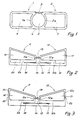
- the transponder according to the invention comprises, like the transponder of Figure 1, two antenna elements, designated by 11 and 12, which are connected on the one hand by a diode , designated by 13, and by a conductor, designated by 14.
- the diode 13 can be of the same kind as the diode 3 of the transponder of FIG. 1.
- the antenna elements 11 and 12 are each pierced with a central opening designated respectively by 16 and 17. These antenna elements 11 and 12 therefore also have the general shape of a loop surrounding a space devoid of any metallic element, which gives the transponder of FIG. 2 the same advantages compared to the known transponder as in the case of FIG. 1.
- the loops constituting the antenna elements 11 and 12 have a general shape of a rectangular trapezoid.
- the small bases 11a and 12a of these trapezoids are arranged opposite one another and parallel to each other, and are connected by the diode 13.
- the sides 11b and 12b of the trapezoids formed by the antenna elements 11 and 12 and which are perpendicular to the bases 11a and 12a are aligned one on the other.
- These sides 11b and 12b each have a slot 18, respectively 19, which extends over part of their length parallel to this length, which is closed on the side of the large bases 11c and 12c of the trapezoids, and which opens on the space separating the small bases 11a and 12a.
- the conductor 14 is thus formed by the outer parts of the sides 11b and 12b, separated from the rest of these sides by the slots 18 and 19, extended and connected to each other by a conductive connecting portion.
- the space 15 delimited by the antenna elements 11 and 12, the diode 13 and the conductor 14 therefore has substantially the shape of a T whose horizontal bar is formed by the slots 18 and 19 and the vertical bar is formed by the space separating the two small bases 11a and 12a between the diode 13 and the conductor 14.
- the antenna elements 11 and 12 and the conductor 14 of the transponder of FIG. 2 are cut from a thin metal sheet and fixed to a support made of suitable dielectric material. who was not represented.
- FIG. 2 also represents a variant of the embodiment of the transponder according to the invention which has just been described.
- the sides 11b and 12b of the antenna elements 11 and 12 are cut along the lines drawn in lines mixed in Figure 2, and the parts designated by 20 and 21 are eliminated. This results in a reduction in the surface of the metal parts of the antenna elements 11 and 12, and therefore in an increase in the efficiency of the transponder, for the same reasons as those which have been mentioned above.
- the transponder shown in FIG. 3 has the same general shape and has the same elements as that of FIG. 2.
- transponders lies in the presence of transverse slots 22 and 23 which intersect respectively the large bases 11 c and 12 c of the antenna elements 11 and 12 of the transponder of FIG. 3.
Landscapes
- Engineering & Computer Science (AREA)
- Radar, Positioning & Navigation (AREA)
- Remote Sensing (AREA)
- Computer Networks & Wireless Communication (AREA)
- Physics & Mathematics (AREA)
- General Physics & Mathematics (AREA)
- Radar Systems Or Details Thereof (AREA)
- Vending Machines For Individual Products (AREA)
- Seal Device For Vehicle (AREA)
- Burglar Alarm Systems (AREA)
Priority Applications (1)
| Application Number | Priority Date | Filing Date | Title |
|---|---|---|---|
| AT87115247T ATE66749T1 (de) | 1986-10-22 | 1987-10-19 | Passives antwortgeraet. |
Applications Claiming Priority (4)
| Application Number | Priority Date | Filing Date | Title |
|---|---|---|---|
| CH4205/86A CH668915A5 (fr) | 1986-10-22 | 1986-10-22 | Transpondeur passif. |
| CH4205/86 | 1986-10-22 | ||
| FR8615911 | 1986-11-13 | ||
| FR8615911A FR2606957B1 (fr) | 1986-11-13 | 1986-11-13 | Transpondeur passif |
Publications (3)
| Publication Number | Publication Date |
|---|---|
| EP0268089A2 true EP0268089A2 (de) | 1988-05-25 |
| EP0268089A3 EP0268089A3 (en) | 1988-06-08 |
| EP0268089B1 EP0268089B1 (de) | 1991-08-28 |
Family
ID=25694916
Family Applications (1)
| Application Number | Title | Priority Date | Filing Date |
|---|---|---|---|
| EP87115247A Expired - Lifetime EP0268089B1 (de) | 1986-10-22 | 1987-10-19 | Passives Antwortgerät |
Country Status (3)
| Country | Link |
|---|---|
| EP (1) | EP0268089B1 (de) |
| AT (1) | ATE66749T1 (de) |
| DE (1) | DE3772523D1 (de) |
Cited By (1)
| Publication number | Priority date | Publication date | Assignee | Title |
|---|---|---|---|---|
| EP0615285A3 (de) * | 1993-03-11 | 1996-09-18 | Csir | Montierung einer elektronischen Schaltung auf einem Substrat. |
Family Cites Families (8)
| Publication number | Priority date | Publication date | Assignee | Title |
|---|---|---|---|---|
| GB692692A (en) * | 1947-12-24 | 1953-06-10 | Charles Alexander Vivian Heath | Improvements in and relating to radio aerials |
| FR2311422A1 (fr) * | 1975-05-15 | 1976-12-10 | France Etat | Doublet replie en plaques |
| FR2346870A1 (fr) * | 1976-04-02 | 1977-10-28 | Mecaniplast | Antenne perfectionnee pour la reception des emissions u.h.f. |
| AT374596B (de) * | 1979-04-20 | 1984-05-10 | Enander Bengt | Zum auffinden von lawinenopfern dienender, am koerper zu tragender antwortsender |
| IT1112913B (it) * | 1979-05-18 | 1986-01-20 | Eigenmann Ludwig | Dispositivo composito per l'esercizio positivo di segnaletica stradale,e metodo per la sua utilizzazione |
| US4642640A (en) * | 1983-04-25 | 1987-02-10 | Sensormatic Electronics Corporation | Signal receptor-reradiator and surveillance tag using the same |
| DE3574186D1 (en) * | 1984-07-30 | 1989-12-14 | Asulab Sa | Passive transponder, specifically for searching victims of an avalanche |
| CA1223346A (en) * | 1984-08-14 | 1987-06-23 | Siltronics Ltd. | Antenna |
-
1987
- 1987-10-19 AT AT87115247T patent/ATE66749T1/de not_active IP Right Cessation
- 1987-10-19 DE DE8787115247T patent/DE3772523D1/de not_active Expired - Lifetime
- 1987-10-19 EP EP87115247A patent/EP0268089B1/de not_active Expired - Lifetime
Cited By (1)
| Publication number | Priority date | Publication date | Assignee | Title |
|---|---|---|---|---|
| EP0615285A3 (de) * | 1993-03-11 | 1996-09-18 | Csir | Montierung einer elektronischen Schaltung auf einem Substrat. |
Also Published As
| Publication number | Publication date |
|---|---|
| EP0268089B1 (de) | 1991-08-28 |
| EP0268089A3 (en) | 1988-06-08 |
| DE3772523D1 (de) | 1991-10-02 |
| ATE66749T1 (de) | 1991-09-15 |
Similar Documents
| Publication | Publication Date | Title |
|---|---|---|
| CH668915A5 (fr) | Transpondeur passif. | |
| EP1407512B1 (de) | Antenne | |
| EP0426972B1 (de) | Ebene Antenne | |
| FR2544871A1 (fr) | Element de reception et de retransmission de signaux pour une etiquette dans une installation de surveillance | |
| EP3613076B1 (de) | Hochfrequenz sende- und empfangsvorrichtung | |
| EP1576696A1 (de) | Antenne mit kleinem volumen insbesonderefür tragbare telefone | |
| FR2779276A1 (fr) | Dispositif de radiocommunication et antenne a fente en boucle | |
| CA2267536A1 (fr) | Dispositif de radiocommunication et antenne bifrequence realisee selon la technique des microrubans | |
| WO2013160611A1 (fr) | Dispositif de radio identification | |
| WO2000038275A1 (fr) | Agencement d'une antenne dans un environnement metallique | |
| FR2906086A1 (fr) | Bobine pour antenne tige, antenne et poignee de portiere pour vehicule | |
| FR2822301A1 (fr) | Antenne a bande elargie pour appareils mobiles | |
| FR2860927A1 (fr) | Antenne interne de faible volume | |
| WO2001035492A1 (fr) | Dispositif de transmission bi-bande et antenne pour ce dispositif | |
| FR2699330A1 (fr) | Boîtier pour circuit intégré à haute fréquence. | |
| EP1225655B1 (de) | Dualband Planarantenne und diese enthaltendes Gerät | |
| EP3725002A1 (de) | Doppeldetektor mit querspulen | |
| EP0172445B1 (de) | Passiver Transponder, insbesondere zur Suche von Lawinenopfern | |
| WO2018172459A1 (fr) | Antenne electromagnetique | |
| FR2747513A1 (fr) | Antenne notamment pour systeme antivol d'un vehicule automobile | |
| FR2704358A1 (fr) | Duplexeur de polarissation à guide d'ondes. | |
| EP0268089B1 (de) | Passives Antwortgerät | |
| FR2606957A1 (fr) | Transpondeur passif | |
| FR2907969A1 (fr) | Antenne mono ou multi-frequences | |
| EP0492022A1 (de) | Breitbandige Funkantenne mit kleinem Stehwellenverhältnis |
Legal Events
| Date | Code | Title | Description |
|---|---|---|---|
| PUAI | Public reference made under article 153(3) epc to a published international application that has entered the european phase |
Free format text: ORIGINAL CODE: 0009012 |
|
| PUAL | Search report despatched |
Free format text: ORIGINAL CODE: 0009013 |
|
| AK | Designated contracting states |
Kind code of ref document: A2 Designated state(s): AT DE IT SE |
|
| AK | Designated contracting states |
Kind code of ref document: A3 Designated state(s): AT DE IT SE |
|
| 17P | Request for examination filed |
Effective date: 19880620 |
|
| 17Q | First examination report despatched |
Effective date: 19900430 |
|
| GRAA | (expected) grant |
Free format text: ORIGINAL CODE: 0009210 |
|
| AK | Designated contracting states |
Kind code of ref document: B1 Designated state(s): AT DE IT SE |
|
| REF | Corresponds to: |
Ref document number: 66749 Country of ref document: AT Date of ref document: 19910915 Kind code of ref document: T |
|
| REF | Corresponds to: |
Ref document number: 3772523 Country of ref document: DE Date of ref document: 19911002 |
|
| ITF | It: translation for a ep patent filed | ||
| PLBE | No opposition filed within time limit |
Free format text: ORIGINAL CODE: 0009261 |
|
| STAA | Information on the status of an ep patent application or granted ep patent |
Free format text: STATUS: NO OPPOSITION FILED WITHIN TIME LIMIT |
|
| 26N | No opposition filed | ||
| EAL | Se: european patent in force in sweden |
Ref document number: 87115247.6 |
|
| PGFP | Annual fee paid to national office [announced via postgrant information from national office to epo] |
Ref country code: AT Payment date: 20040923 Year of fee payment: 18 |
|
| PGFP | Annual fee paid to national office [announced via postgrant information from national office to epo] |
Ref country code: SE Payment date: 20040924 Year of fee payment: 18 Ref country code: DE Payment date: 20040924 Year of fee payment: 18 |
|
| PG25 | Lapsed in a contracting state [announced via postgrant information from national office to epo] |
Ref country code: IT Free format text: LAPSE BECAUSE OF NON-PAYMENT OF DUE FEES;WARNING: LAPSES OF ITALIAN PATENTS WITH EFFECTIVE DATE BEFORE 2007 MAY HAVE OCCURRED AT ANY TIME BEFORE 2007. THE CORRECT EFFECTIVE DATE MAY BE DIFFERENT FROM THE ONE RECORDED. Effective date: 20051019 Ref country code: AT Free format text: LAPSE BECAUSE OF NON-PAYMENT OF DUE FEES Effective date: 20051019 |
|
| PG25 | Lapsed in a contracting state [announced via postgrant information from national office to epo] |
Ref country code: SE Free format text: LAPSE BECAUSE OF NON-PAYMENT OF DUE FEES Effective date: 20051020 |
|
| PG25 | Lapsed in a contracting state [announced via postgrant information from national office to epo] |
Ref country code: DE Free format text: LAPSE BECAUSE OF NON-PAYMENT OF DUE FEES Effective date: 20060503 |
|
| EUG | Se: european patent has lapsed |