EP0267397B1 - Dispositif de transmission de signaux de commande, notamment pour avions - Google Patents
Dispositif de transmission de signaux de commande, notamment pour avions Download PDFInfo
- Publication number
- EP0267397B1 EP0267397B1 EP87113946A EP87113946A EP0267397B1 EP 0267397 B1 EP0267397 B1 EP 0267397B1 EP 87113946 A EP87113946 A EP 87113946A EP 87113946 A EP87113946 A EP 87113946A EP 0267397 B1 EP0267397 B1 EP 0267397B1
- Authority
- EP
- European Patent Office
- Prior art keywords
- network
- signal
- control
- arrangement according
- arrangement
- Prior art date
- Legal status (The legal status is an assumption and is not a legal conclusion. Google has not performed a legal analysis and makes no representation as to the accuracy of the status listed.)
- Expired - Lifetime
Links
Images


Classifications
-
- H—ELECTRICITY
- H04—ELECTRIC COMMUNICATION TECHNIQUE
- H04B—TRANSMISSION
- H04B10/00—Transmission systems employing electromagnetic waves other than radio-waves, e.g. infrared, visible or ultraviolet light, or employing corpuscular radiation, e.g. quantum communication
- H04B10/27—Arrangements for networking
-
- B—PERFORMING OPERATIONS; TRANSPORTING
- B64—AIRCRAFT; AVIATION; COSMONAUTICS
- B64C—AEROPLANES; HELICOPTERS
- B64C13/00—Control systems or transmitting systems for actuating flying-control surfaces, lift-increasing flaps, air brakes, or spoilers
- B64C13/24—Transmitting means
- B64C13/38—Transmitting means with power amplification
- B64C13/50—Transmitting means with power amplification using electrical energy
-
- G—PHYSICS
- G05—CONTROLLING; REGULATING
- G05D—SYSTEMS FOR CONTROLLING OR REGULATING NON-ELECTRIC VARIABLES
- G05D1/00—Control of position, course, altitude or attitude of land, water, air or space vehicles, e.g. using automatic pilots
- G05D1/0055—Control of position, course, altitude or attitude of land, water, air or space vehicles, e.g. using automatic pilots with safety arrangements
- G05D1/0061—Control of position, course, altitude or attitude of land, water, air or space vehicles, e.g. using automatic pilots with safety arrangements for transition from automatic pilot to manual pilot and vice versa
-
- G—PHYSICS
- G05—CONTROLLING; REGULATING
- G05D—SYSTEMS FOR CONTROLLING OR REGULATING NON-ELECTRIC VARIABLES
- G05D1/00—Control of position, course, altitude or attitude of land, water, air or space vehicles, e.g. using automatic pilots
- G05D1/0055—Control of position, course, altitude or attitude of land, water, air or space vehicles, e.g. using automatic pilots with safety arrangements
- G05D1/0077—Control of position, course, altitude or attitude of land, water, air or space vehicles, e.g. using automatic pilots with safety arrangements using redundant signals or controls
-
- H—ELECTRICITY
- H04—ELECTRIC COMMUNICATION TECHNIQUE
- H04B—TRANSMISSION
- H04B10/00—Transmission systems employing electromagnetic waves other than radio-waves, e.g. infrared, visible or ultraviolet light, or employing corpuscular radiation, e.g. quantum communication
- H04B10/27—Arrangements for networking
- H04B10/278—Bus-type networks
Definitions
- control movements can be transmitted from the pilot to the rudder, for example, by mechanical devices such as cables, rods, rotating shafts or corresponding combinations. It is also known to transmit electrical digital control signals via corresponding data lines to the rudders, where they are converted into corresponding control movements by means of digitally controllable electrical or hydraulic drives.
- this has the disadvantage that the data traffic running on the data lines can be disrupted by strong electromagnetic fields, such as can occur in the event of a lightning strike or an electrical short circuit.
- the object of the invention is to design an arrangement, in particular for aircraft, for the transmission of control signals in such a way that the trouble-free functioning of the overall system is ensured even if several data lines fail.
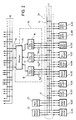
- Aircraft F includes, among other things, the engines 8, 8 'and the control elements 9, the schematic representation indicating the control columns 9a and pedals.
- the line system for the transmission of control signals mainly has a plurality of signal processors 10 and a multi-meshed network of optical fibers consisting of longitudinal lines 11 and cross lines 12, which is connected to addressable servo units 14.
- Nodes 13 consist of branches of a known type, e.g. B. in the form of star or T couplers.
- the control elements 9 are designed such that they deliver a digital light signal corresponding to the control command.
- the servo units 14 arranged on the periphery of the network have devices for converting the incoming light signal into a control movement. In addition, they have facilities that the current position z. B. determine a rudder and emit a corresponding light signal to the longitudinal lines 11.
- the data traffic running between the signal processors 10 and the peripheral devices connected via the longitudinal lines 11 is carried out cyclically, ie the signal processors 10 issue addressed information signals in a fixed polling cycle, e.g. B. from the servo units 14, which in turn answer them with addressed information signals.
- the data traffic running here is defined in the form of telegrams with a fixed word length. These telegrams are impressed on a carrier frequency in the form of digital frequency modulation, the light signal ultimately having an amplitude modulation corresponding to the carrier frequency. In this way, a very high level of interference immunity is achieved with respect to possible interference from extraneous light.
- the meshing ensures that the signal arrives in many ways from the signal processors 10 to the servo unit 14 addressed, which further increases the reliability of the system.
- the system shown is three-fold, ie in the fuselage, in the wing and in the tail units three longitudinal lines 11 are arranged with corresponding transverse lines 12 and three servo units 14 are provided per rudder, control surface or the like.
- the signal processors 10 contain the main control circuit of the entire arrangement. This unit is also designed in triplicate to increase reliability.
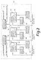
- FIG. 2 shows the circuit of one of the signal processors 10, which essentially consists of a mixer 15 and three information systems 16, 17 and 18.
- the mixer 15 is connected to a meshed transmitter network 20 made of optical fibers via triple optical cables 19.
- the triple output of the mixer 15 is connected to one of the information units 16 to 18.
- Each unit 16 to 18 also has three connection light lines 16a to 18a, each of which is connected to the network 24 of the longitudinal lines 11 and cross lines 12.
- the mixer 15 takes on the task here, the z. B. coming from the control column to prepare digital light signals so that they are forwarded to the information systems 16 to 18 while taking further information into account. Are the mixer 15 z. B.
- the mixer 15 forms a difference signal that serves to set the target altitude the information systems 16 to 18 are entered into the network 24, this telegram addressed to the servo unit 14.01 of the elevator is now received by this unit and converted into a corresponding deflection of the rudder 1, which returns the aircraft to its target without the pilot's influence - flight altitude returns.
- actual course values supplied by a navigation device 23 can be compared by the mixer 15 with a predetermined target course.
- the resulting difference signal is then sent to the Servo unit 14.02 of rudder 2 and the control command addressed to servo units 14.03 and 14.04 of ailerons 3 are converted and fed to said servo units via information systems 16, 17 and 18 and further via network 24. These respond with a rudder deflection, which causes the required course correction.
- a display and operating device (not shown) connected to the mixer 15 via the transmitter network 20 is used, among other things, for the graphic representation of the target and actual values using conventional symbols. If the arrangement is switched to manual operation, the setpoint / actual comparison by the mixer is omitted and the control commands arriving via the encoder network 20 are forwarded directly to the servo units concerned in the form of corresponding telegrams.
- All control elements 9 which emit a control command are connected to the transmitter network 20 via a triple optical fiber.
- the task of the information systems 16 to 18 is essentially to control the traffic of the data entering and leaving the mixer unit 15 by a certain clock and to provide the command or query telegrams with the appropriate addresses.
- FIG. 3 shows the internal circuitry of a mixer 15 with two connection units 39 and 40, each associated with a control column 9a, with three central processor units 41, 42 and 43, each of which is assigned a memory 44, 45 and 46.
- the mixer 15 also has a corresponding connection unit, not shown here, for each organ that can issue a control command.
- the mixer 15 also has a vertical reference 47, 48, 49 and a horizontal reference 50, 51, 52 for each store.
- Optical fibers are used for connection to the control columns 9a and force simulators 35.
- the single ones Internal functional units of the mixer 15 are connected to one another according to FIG. 5 by electrical lines.
- the connections to the information systems 16 to 18 also take place via electrical lines.
- connection unit 39 which in turn consists essentially of amplifiers and code converters.
- the signals mentioned are amplified and recoded and routed to the internal data bus, which is connected to the central processor units 41, 42 and 43.
- a priority circuit within the connection units ensures that the signals of the control column 9a 'have priority until the control column 9a "is switched on by operation and this then takes over the leadership.
- those of the references 47 to 49 and 50 to 52 supplied data corresponding to the actual position of the aircraft are stored and compared with one another via the processor units 41 to 43.
- processor unit 41 to 43 Processor unit with deviating information is identified as faulty and blocked via the internal data bus. This is done by means of a special error code signal. It is also processor units 41 to 43 that carry out the necessary operations for the aforementioned automatic flight guidance.
- a corresponding processor is e.g. under the designation PDP 11/7 1, the entire arrangement has three signal processors 10 and thus also three mixers 15, which results in a corresponding increase in reliability.
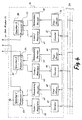
- FIG. 4 shows a block diagram of an optronic information system, as is provided in triplicate according to FIG. 2 within the signal processor 10 with the positions 16, 17 and 18.
- the illustrated System has three processors 53, 54, 55 with three memories 56, 57, 58, three coders / modulators 59, 60, 61, three demodulator / decoders 62, 63, 64, three transmitters 65, 66, 67 and three receivers 68, 69, 70, which are interconnected.
- An essential component of the transmitters 65 to 67 is a laser diode, which can emit a light signal to the network 24.
- the receivers essentially consist of a silicon phototransistor, which serves as a detector for light signals arriving via the network 24, ie converts them back into electrical signals.
- the information system shown consists of three branches that work in parallel to increase reliability. To explain the mode of operation, only the branch shown on the left, consisting of the processor 53 with the memory 56 and the encoder / modulator 59, the demodulator / decoder 62, the transmitter 65 and the receiver 68, is considered first.
- This circuit controls the data traffic running between the network 24 and the mixer 15, an oscillator integrated in the processor 53 acting as a clock. An electrical signal coming from the mixer 15 to the processor 53 is fed to the encoder / modulator 59.
- the data telegram is converted from the processor-related to the peripheral-related word and address structure.
- the telegram then passes through the modulator part, where it is impressed on a high-frequency carrier in the form of frequency modulation.
- the corresponding pure data content is then recovered in an intermediate step by demodulation and impressed on a fixed other carrier by amplitude modulation.
- the resulting signal is amplified within the transmitter 65 and fed to the laser diode, which emits a light signal analogous to the diode current to the network 24.
- a light signal arriving via the network 24 is received by the receiver 68 and converted back into an amplitude-modulated electrical signal by the built-in phototransistor, which electrical signal then reaches the demodulator / decoder 62.
- FIG. 5 shows a block diagram of a display and operating device 92.
- the device has a processor unit 93, an electronic image unit 94, a screen 95, a keyboard 95a, a coder 96, a transmitter 97, a decoder 98 and one Receiver 99, which are interconnected.
- the transmitter 97 and the receiver 99 are connected to the transmitter network 20 via optical fibers.
- Via the alphanumeric keyboard 95a which, for. B. works according to the ASCI code (American Standard Code for Information Interchange), operating data is entered into the encoder network 20. For fixed operating modes, certain selection keys provided with corresponding symbols are available.
- ASCI code American Standard Code for Information Interchange
- the processor unit 93 has the task, inter alia, of processing the signals supplied by the keyboard 95a in such a way that they arrive in the form of queried data telegrams via the encoder 96 and the transmitter 97 via optical fibers to the mixer 15.
- the screen 95 is connected to the processor unit 93 via the electronic image unit 94.
- the image unit 94 essentially comprises a signal generator and a code converter matrix, as are usually used for image display. Such a circuit is known from Klein: "Microcomputer systems", Francis Verlag, Kunststoff, 1979, 2nd edition p. 32.
- the screen 95 is designed as a semiconductor screen and serves both to display the current position of the aircraft F and to display control corrections that have been made.
- the signal generator of the image unit 94 is used to prepare the symbolic representation of position and course information (bars, course numbers), to produce alphanumeric characters according to the ASCI code and to prepare the symbols for the control commands.
- the code converter matrix controls the dot matrix fields of the screen 95, so that the digital signals present in the code of the signal generator are converted into the corresponding representations.
- the entire arrangement has three of the display and operating devices 92 described above, which correspond to the mixers 15 via the transmitter network 20.
- both pilots and the flight engineer each have their own display and operating device 92, the representations shown and the operating measures carried out generally being completely different owing to the different tasks of the operating personnel.
- the possibilities that result from appropriate programming of the circuit shown are only hinted at.
- FIG. 6 shows a block diagram of a dialog device 100 with which there is a sensible embodiment of the arrangement results.
- Dialog device 100 essentially consists of a speech analysis unit 101, which is connected to a microphone, and a speech synthesis unit 102, which is connected to a loudspeaker.
- the dialog device 100 corresponds to the processor unit 93 of the display and control device 92 according to FIG. 8 and allows a linguistic dialog of the operator with the arrangement described.
- the speech synthesis takes place within the unit 102 by means of a PROM speech encoder, which breaks down the telegrams delivered by the processor unit 93 and compiles the corresponding words to be output on the basis of a syllable treasure stored here, and these tone-frequency signals to the loudspeaker via a power amplifier, not shown here feeds.
- a PROM speech encoder which breaks down the telegrams delivered by the processor unit 93 and compiles the corresponding words to be output on the basis of a syllable treasure stored here, and these tone-frequency signals to the loudspeaker via a power amplifier, not shown here feeds.
- voice coder or decoder are known per se and z. B. in the magazine “Electronics", Issue 14, 1980, described from page 54 on the basis of application examples.
- Fig. 7 shows an internal basic circuit s.
- the measuring and switching unit 115 according to FIG. 10.
- the unit essentially consists of an A / D converter (analog / digital converter) 152 and a switching unit 157.
- the transmission unit 110 is also expediently shown here with its internal circuit.
- This unit essentially consists of a coder 153, a transmitter 154, a receiver 155 and a decoder 156, which are connected to one another as indicated in the circuit.
- the operation of the measuring and switching unit 115 will now be explained using the example of the auxiliary turbine 112.
- the output voltage of the generator 113 is measured by means of a sensor 158, for example, and input into the A / D converter 152 in the form of a corresponding analog signal. This generates a corresponding digital signal, which it forwards to the encoder 153.
- the coder 153 provides this signal with the address of the test unit 135 and forwards the now complete telegram in terms of content to the transmitter 154.
- the cross connection 160 ensures that the telegram is only forwarded to the transmitter 154 if a correspondingly addressed query telegram from the test unit 135 has been received via the receiver 155 and the decoder 156.
- the transmitter 154 and the receiver 155 are connected to the network 24 via the light guides 161 and 162 and the corresponding telegrams are exchanged in the form of digital light signals. With the help of further sensors, other variables can also be measured and passed on to the test unit 135 be such. B. the turbine speed, the generator current, the hydraulic pressure, etc. If the test unit detects a defect in the auxiliary turbine, a telegram addressed to the switching unit 157 arrives via the network 24 with the shutdown command via the receiver 155, which is recognized by the decoder 156 and is read, which then forwards a corresponding signal to the switching unit 157.
- the switching unit 157 causes the separation of all operative connections of the aircraft to be released for safety reasons with the auxiliary turbine 112, the generator 113 and the pump 114.
- a switch 159 may be provided for switching off the generator 113.
Landscapes
- Engineering & Computer Science (AREA)
- Automation & Control Theory (AREA)
- Physics & Mathematics (AREA)
- Aviation & Aerospace Engineering (AREA)
- Remote Sensing (AREA)
- Radar, Positioning & Navigation (AREA)
- General Physics & Mathematics (AREA)
- Signal Processing (AREA)
- Computer Networks & Wireless Communication (AREA)
- Electromagnetism (AREA)
- Computing Systems (AREA)
- Selective Calling Equipment (AREA)
- Testing And Monitoring For Control Systems (AREA)
Claims (8)
- Installation notamment pour avion, pour la transmission de signaux de commande servant à commander des surfaces de commande (volets) par l'intermédiaire d'un système de données commandé par des microprocesseurs, et dont les différentes lignes sont des fibres optiques, montage caractérisé en ce que les fibres optiques forment un réseau à mailles multiples (24) et les organes de commande (9), pour générer les ordres de commande sous forme optique, numérique sont reliés par des mélangeurs (15) montés dans les processeurs de signaux (10) et des systèmes d'information (16, 17, 18) sur le réseau (24) et en ce que les surfaces de commande (1, 2, 3, 4, 5) ainsi que d'autres éléments de commande sont commandés et actionnés par des moteurs d'asservissement (14) adressés par le réseau.
- Installation selon la revendication 1, caractérisée en ce que les servomoteurs (14) comportent tous des capteurs de position (78) fournissant un signal en réponse à un signal de demande, correspondant à la position de fonctionnement instantanée d'une surface de commande (1, 2, 3, 4, 5).
- Installation selon la revendication 1 ou 2, caractérisée en ce qu'un réseau de capteurs (20) situé au niveau du cockpit est prévu entre les organes de commande (9) et le mélangeur (15) pour l'échange de signaux.
- Installation selon l'une des revendications 1 à 5, caractérisée par au moins un appareil d'affichage et de manoeuvre (92) avec un écran image (95) et un clavier (95a) reliés aux mélangeurs par le réseau de capteurs (20).
- Installation selon l'une des revendications 1 à 6, caractérisée par un appareil de dialogue (100) relié à l'appareil d'affichage et de manoeuvre (92) et qui comprend une unité d'analyse vocale (101) et une unité de synthèse vocale.
- Installation selon la revendication 1, caractérisée en ce que les systèmes d'information (16, 17, 18) comportent chacun au moins une mémoire (56), un processeur (53), un codeur-moduleur (59), un démoduleur-décodeur (62), un émetteur (65) et un récepteur (68).
- installation selon les revendications 1 à 6, caractérisée en ce que tous les conducteurs de lumière du réseau (24) et du réseau de capteurs (20) ainsi que les processeurs de signaux (10), les mélangeurs (15) et les systèmes d'information (16, 17, 18) sont branchés en parallèle de manière triple.
- Installation selon les revendications 1 à 7, caractérisée en se que les conducteurs de lumière du réseau (24) se compose de conducteur fibre-optique presentent une teinture.
Priority Applications (1)
| Application Number | Priority Date | Filing Date | Title |
|---|---|---|---|
| EP87113946A EP0267397B1 (fr) | 1980-09-02 | 1981-07-23 | Dispositif de transmission de signaux de commande, notamment pour avions |
Applications Claiming Priority (5)
| Application Number | Priority Date | Filing Date | Title |
|---|---|---|---|
| DE3032918A DE3032918C2 (de) | 1980-09-02 | 1980-09-02 | Passives Leitungssystem, insbesondere für Luftfahrzeuge, zur Übertragung von Steuersignalen |
| DE3032918 | 1980-09-02 | ||
| DE3111722A DE3111722C2 (de) | 1981-03-25 | 1981-03-25 | Passives Leitungssystem für Luftfahrzeuge zur Übertragung von Steuersignalen |
| DE3111722 | 1981-03-25 | ||
| EP87113946A EP0267397B1 (fr) | 1980-09-02 | 1981-07-23 | Dispositif de transmission de signaux de commande, notamment pour avions |
Related Parent Applications (1)
| Application Number | Title | Priority Date | Filing Date |
|---|---|---|---|
| EP81105812.2 Division | 1981-07-23 |
Publications (3)
| Publication Number | Publication Date |
|---|---|
| EP0267397A2 EP0267397A2 (fr) | 1988-05-18 |
| EP0267397A3 EP0267397A3 (en) | 1988-12-21 |
| EP0267397B1 true EP0267397B1 (fr) | 1992-09-16 |
Family
ID=27188853
Family Applications (1)
| Application Number | Title | Priority Date | Filing Date |
|---|---|---|---|
| EP87113946A Expired - Lifetime EP0267397B1 (fr) | 1980-09-02 | 1981-07-23 | Dispositif de transmission de signaux de commande, notamment pour avions |
Country Status (1)
| Country | Link |
|---|---|
| EP (1) | EP0267397B1 (fr) |
Families Citing this family (5)
| Publication number | Priority date | Publication date | Assignee | Title |
|---|---|---|---|---|
| EP0200352A3 (fr) * | 1985-03-25 | 1990-04-25 | British Aerospace Public Limited Company | Système de commande à calculateur |
| US5136841A (en) * | 1989-02-27 | 1992-08-11 | Zimmerman Ward H | Aircraft propulsion control system |
| US5044155A (en) * | 1989-02-27 | 1991-09-03 | The Boeing Company | Aircraft propulsion control system |
| US5001638A (en) * | 1989-04-18 | 1991-03-19 | The Boeing Company | Integrated aircraft air data system |
| FR2692687B1 (fr) * | 1992-06-18 | 1994-09-16 | Aerospatiale | Système de commande à sources de commande interactives, permettant d'accéder à un nombre quelconque de systèmes hétérogènes. |
Family Cites Families (5)
| Publication number | Priority date | Publication date | Assignee | Title |
|---|---|---|---|---|
| US3076510A (en) * | 1959-07-13 | 1963-02-05 | Alfred J Piel | Air propelled electricity generator for moving vehicles |
| DE2402619A1 (de) * | 1974-01-21 | 1975-07-31 | Krupp Gmbh | Vorrichtung zur steuerung von fernlenkkoerpern |
| US3964020A (en) * | 1975-03-06 | 1976-06-15 | Hughes Aircraft Company | High voltage system with self-test circuitry |
| FR2391908A1 (fr) * | 1977-05-25 | 1978-12-22 | Wieczorek Julien | Des dispositifs de pilotage par cables avec fibres optiques |
| DE3008478A1 (de) * | 1979-05-30 | 1980-12-11 | Sundstrand Corp | Steueranordnung und -verfahren fuer elektrisches generator- und verteilungssystem |
-
1981
- 1981-07-23 EP EP87113946A patent/EP0267397B1/fr not_active Expired - Lifetime
Also Published As
| Publication number | Publication date |
|---|---|
| EP0267397A2 (fr) | 1988-05-18 |
| EP0267397A3 (en) | 1988-12-21 |
Similar Documents
| Publication | Publication Date | Title |
|---|---|---|
| EP0268041B1 (fr) | Servocommande pour actionner les surfaces de commande d'un système de commande de vol ou similaire | |
| DE69329751T2 (de) | Flugsteuerungssystem für Flugmaschine | |
| DE2814811A1 (de) | Vorrichtung zur ermittlung von kurs- und/oder betriebsdaten bzw. sonstigen flugparametern von luftfahrzeugen | |
| DE2640756C2 (de) | Einrichtung zur gesicherten Datenübertragung bei spurgebundenen Fahrzeugen | |
| DE3613196A1 (de) | Luftfahrtelektroniksteuer- bzw. -regelsystem | |
| DE60111303T2 (de) | Flugzeug mit elektrischer Flugsteuerung, versehen mit einem Autopilotsystem | |
| DE69404763T2 (de) | Gerät zur automatischen Flugzeugsteuerung | |
| DE2808792A1 (de) | Positioniersystem | |
| EP0267397B1 (fr) | Dispositif de transmission de signaux de commande, notamment pour avions | |
| DE2824168C3 (de) | Einrichtung zur Steuerung von spurgebundenen Fahrzeugen im Zugverband | |
| EP0024284B1 (fr) | Dispositif de commande de secours | |
| DE3111722C2 (de) | Passives Leitungssystem für Luftfahrzeuge zur Übertragung von Steuersignalen | |
| EP0267398B1 (fr) | Dispositif de transmission de signaux de commande, notamment pour avions | |
| DE3032918A1 (de) | Anordnung, insbesondere fuer luftfahrzeuge zur uebertragung von steuersignalen | |
| DE102011115356A1 (de) | Flugsteuerungssystem sowie ein Bussystem für ein Flugzeug | |
| DE2710466A1 (de) | Steuersystem zur fehlerueberwachung | |
| DE3050760C2 (de) | Servo-Einheit zur Betätigung von zu einem Flugsteuerungs-System gehörenden Steuerflächen oder dgl. | |
| DE10041989B4 (de) | Fehlertolerante Sensorik | |
| DE1623557B2 (de) | Redundantes kreiselsystem mit drei kreiselgeraeten fuer luftfahrzeuge | |
| DE69118618T2 (de) | Kodier- und Dekodiervorrichtung mit eigener Taktschaltung | |
| DE3618087A1 (de) | Fehlertoleranter empfaenger | |
| DE102006039671A1 (de) | Modulares elektronisches Flugsteuerungssystem | |
| DE2517102A1 (de) | System zum ankoppeln des datenprocessors einer datenverarbeitungsanlage an periphere einheiten | |
| DE3906846A1 (de) | Redundante rechneranordnung fuer steuersysteme | |
| DE2120662A1 (de) | Steuerungssystem |
Legal Events
| Date | Code | Title | Description |
|---|---|---|---|
| PUAI | Public reference made under article 153(3) epc to a published international application that has entered the european phase |
Free format text: ORIGINAL CODE: 0009012 |
|
| 17P | Request for examination filed |
Effective date: 19871015 |
|
| AC | Divisional application: reference to earlier application |
Ref document number: 46875 Country of ref document: EP |
|
| AK | Designated contracting states |
Kind code of ref document: A2 Designated state(s): FR GB IT SE |
|
| PUAL | Search report despatched |
Free format text: ORIGINAL CODE: 0009013 |
|
| AK | Designated contracting states |
Kind code of ref document: A3 Designated state(s): FR GB IT SE |
|
| 17Q | First examination report despatched |
Effective date: 19910211 |
|
| RAP1 | Party data changed (applicant data changed or rights of an application transferred) |
Owner name: DEUTSCHE AIRBUS GMBH |
|
| GRAA | (expected) grant |
Free format text: ORIGINAL CODE: 0009210 |
|
| AC | Divisional application: reference to earlier application |
Ref document number: 46875 Country of ref document: EP |
|
| AK | Designated contracting states |
Kind code of ref document: B1 Designated state(s): FR GB IT SE |
|
| ET | Fr: translation filed | ||
| ITF | It: translation for a ep patent filed | ||
| GBT | Gb: translation of ep patent filed (gb section 77(6)(a)/1977) |
Effective date: 19921221 |
|
| PLBE | No opposition filed within time limit |
Free format text: ORIGINAL CODE: 0009261 |
|
| STAA | Information on the status of an ep patent application or granted ep patent |
Free format text: STATUS: NO OPPOSITION FILED WITHIN TIME LIMIT |
|
| 26N | No opposition filed | ||
| EAL | Se: european patent in force in sweden |
Ref document number: 87113946.5 |
|
| PGFP | Annual fee paid to national office [announced via postgrant information from national office to epo] |
Ref country code: SE Payment date: 19980706 Year of fee payment: 18 |
|
| PGFP | Annual fee paid to national office [announced via postgrant information from national office to epo] |
Ref country code: GB Payment date: 19980713 Year of fee payment: 18 |
|
| PGFP | Annual fee paid to national office [announced via postgrant information from national office to epo] |
Ref country code: FR Payment date: 19980730 Year of fee payment: 18 |
|
| PG25 | Lapsed in a contracting state [announced via postgrant information from national office to epo] |
Ref country code: GB Free format text: LAPSE BECAUSE OF NON-PAYMENT OF DUE FEES Effective date: 19990723 |
|
| PG25 | Lapsed in a contracting state [announced via postgrant information from national office to epo] |
Ref country code: SE Free format text: THE PATENT HAS BEEN ANNULLED BY A DECISION OF A NATIONAL AUTHORITY Effective date: 19990730 |
|
| PG25 | Lapsed in a contracting state [announced via postgrant information from national office to epo] |
Ref country code: FR Free format text: THE PATENT HAS BEEN ANNULLED BY A DECISION OF A NATIONAL AUTHORITY Effective date: 19990731 |
|
| GBPC | Gb: european patent ceased through non-payment of renewal fee |
Effective date: 19990723 |
|
| EUG | Se: european patent has lapsed |
Ref document number: 87113946.5 |
|
| REG | Reference to a national code |
Ref country code: FR Ref legal event code: ST |