EP0267240B1 - Selbsttätige anordung zum einstellen von skiern - Google Patents
Selbsttätige anordung zum einstellen von skiern Download PDFInfo
- Publication number
- EP0267240B1 EP0267240B1 EP87903162A EP87903162A EP0267240B1 EP 0267240 B1 EP0267240 B1 EP 0267240B1 EP 87903162 A EP87903162 A EP 87903162A EP 87903162 A EP87903162 A EP 87903162A EP 0267240 B1 EP0267240 B1 EP 0267240B1
- Authority
- EP
- European Patent Office
- Prior art keywords
- ski
- grinding
- plate
- slideable
- angle
- Prior art date
- Legal status (The legal status is an assumption and is not a legal conclusion. Google has not performed a legal analysis and makes no representation as to the accuracy of the status listed.)
- Expired
Links
- 230000007246 mechanism Effects 0.000 claims description 7
- 230000000694 effects Effects 0.000 claims description 3
- 230000002441 reversible effect Effects 0.000 claims 1
- 239000002184 metal Substances 0.000 description 33
- 229910052751 metal Inorganic materials 0.000 description 33
- 238000000034 method Methods 0.000 description 6
- 239000000463 material Substances 0.000 description 5
- 239000011152 fibreglass Substances 0.000 description 2
- 239000004033 plastic Substances 0.000 description 2
- 239000002023 wood Substances 0.000 description 2
- 229910000831 Steel Inorganic materials 0.000 description 1
- 229910000746 Structural steel Inorganic materials 0.000 description 1
- 238000013459 approach Methods 0.000 description 1
- 239000011324 bead Substances 0.000 description 1
- 230000006835 compression Effects 0.000 description 1
- 238000007906 compression Methods 0.000 description 1
- 238000004519 manufacturing process Methods 0.000 description 1
- 238000005259 measurement Methods 0.000 description 1
- 230000001105 regulatory effect Effects 0.000 description 1
- 229920005989 resin Polymers 0.000 description 1
- 239000011347 resin Substances 0.000 description 1
- 238000000926 separation method Methods 0.000 description 1
- 239000010959 steel Substances 0.000 description 1
Images

Classifications
-
- A—HUMAN NECESSITIES
- A63—SPORTS; GAMES; AMUSEMENTS
- A63C—SKATES; SKIS; ROLLER SKATES; DESIGN OR LAYOUT OF COURTS, RINKS OR THE LIKE
- A63C11/00—Accessories for skiing or snowboarding
- A63C11/04—Accessories for skiing or snowboarding for treating skis or snowboards
- A63C11/06—Edge-sharpeners
-
- B—PERFORMING OPERATIONS; TRANSPORTING
- B24—GRINDING; POLISHING
- B24B—MACHINES, DEVICES, OR PROCESSES FOR GRINDING OR POLISHING; DRESSING OR CONDITIONING OF ABRADING SURFACES; FEEDING OF GRINDING, POLISHING, OR LAPPING AGENTS
- B24B3/00—Sharpening cutting edges, e.g. of tools; Accessories therefor, e.g. for holding the tools
- B24B3/006—Sharpening cutting edges, e.g. of tools; Accessories therefor, e.g. for holding the tools for edges of skis, snowboards or the like
Definitions
- This invention relates generally to devices for tuning snow skis and, more particularly, to a device adapted to automatically bevel the metal edges of snow skis in direct corrolation with the width of the ski.
- Snow skis that are utilized for alpine skiing are made from various materials, including wood, plastic, fiberglass and the like but, regardless of the material from which the ski is made, they all contain metal edges extending along the length of the ski on opposite sides of the bottom surface of the ski in coplanar relationship therewith.
- the metal edges when fabricated into the ski have an outer edge forming a right angle with the vertical side walls of the ski, but if this right angle were to extend the entire length of the ski, it would be very difficult to turn the skis, as the right angle on the edge inhibits the turning of the ski and encourages the ski to tract straightforwardly. Accordingly, it is desirable to facilitate turning of the skis to place a slight bevel on the metal edges so that the bottom surface of the metal edge forms a slight angle, sometimes up to two degrees, relative to the bottom surface of the ski.
- Alpine snow skis have another similar characteristic in that the leading and trailing ends of the skis are wider than the longitudinal center of the ski. Accordingly, it has been concluded that the bevel placed on the metal edges can have a direct relationship to the width of the ski so that the greater the width, the greater the bevel should be. Accordingly, near the leading and trailing ends of the ski, where it is widest, the bevel is the greatest so as to enable the skis to be turned easily. Similarly, at the longitudinal center of the ski, where the ski is narrowest, the bevel is the smallest to enable the desired carving of the ski through turns.
- alpine skis are fabricated with different materials which are bonded together with various resins or other bonding mediums, and these bonding mediums typically take weeks to cure. For this reason, the manufacturers of alpine snow skis typically ship the skis to retail locations before the bonding medium has totally cured. Accordingly, when the skis finally reach the retail destination or shortly thereafter, and the bonding medium has cured, the various bonded components of the skis may have contracted during the curing process so that the bottom surface of the skis are not smooth, as desired, and may not be coplanar with the metal edges.
- the skis after the skis have reached the retail destination, it is necessary to tune the skis by grinding the bottoms of the skis so that they are smooth, as desired, and then filing the metal edges until the bottom surfaces thereof are substantially coplanar with the bottoms of the skis.
- the metal edges should be beveled during this same tuning process so as to increase the angle between the bottom surfaces of the metal edges and the bottom surfaces of the skis near the leading and trailing ends of the skis so that the skis will properly perform for the ultimate purchaser.
- skis cannot be tuned at the manufacturing site because they are usually shipped before the bonding medium has completely cured, it is a natural consequence that the tuning of skis, including the beveling of the metal edges, is done by a large number of people resulting in a lack of uniformity from retail location to retail location. Accordingly, the ultimate purchaser of the skis does not get a predictable product.
- U.S. Patent No. 4,442,636 issued to Obland, discloses a hand-operated device for simultaneously sharpening both edges of a ski, but again, the edges are sharpened at right angles, and there is no suggestion of means for beveling the edges of the ski.
- U.S. Patent No. 4,030,382 issued to Nilsson, et al., discloses a device for sharpening the steel edges of a ski and includes an embodiment wherein the sharpening element of the device can be inclined so that an angle less than ninety degrees can be imparted to the metal edge establishing a bevel as opposed to a right-angled edge on the ski.
- This device has no suggestion of relating the bevel to the width of the ski.
- DE-A-33 41 062 discloses a device for grinding the bottom edge of a ski.
- the known device has a motor driven endless grinding belt.
- a guide shoe for the belt is manually adjustable about an axis parallel to the belt movement whereby the bottom edge of the ski can be ground at an angle relative to the bottom of the ski.
- the object of the present invention is to provide a device adapted to grind a predetermined bevel into the metal edges of snow skis whereby the angle of the bevel can automatically vary along the length of the ski.
- a tuning device for grinding the bottom edge of a ski having a variable width along its length comprising frame means adapted to be moved along the length of the ski, grinding means operably mounted on said frame means, and means for varying the angle of said grinding means relative to the bottom of the ski, characterized by servo mechanism means on said frame means, operably associated with said grinding means and including sensing means to sense the width of the ski and automatic means to adjust the angle of the grinding means in a direct relation to the width of the ski sensed by said sensing means.
- the servo mechanism can effect a greater angle of bevel (i. e., a larger angle between the bottom surface of the metal edge and the bottom surface of the ski) at wider locations along the length of the ski so that a greater bevel is established near the leading and trailing ends of the ski where the ski is the widest.
- a greater angle of bevel i. e., a larger angle between the bottom surface of the metal edge and the bottom surface of the ski
- a relatively large angle of bevel for example approaching 2 degrees
- the angle of bevel is reduced, for example to approximately .5 degrees.
- a greater angle of bevel is established.
- the metal edges are beveled so as to have a greater angle of bevel near the leading and trailing ends to enable the ski to be turned more easily and a relative smaller angle of bevel near the longitudinal center of the ski where it is important to retain a fairly sharp edge to assist the skier in carving desired turns.
- the present invention provides a new and improved means for beveling the metal edges of alpine snow skis in an automated more expeditious and uniform manner to reduce labor costs involved in the tuning of snow skis and to attain uniform and predictable results.
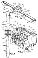
- the ski tuning device 20 according to one embodiment of the present invention is shown supported on the bottom surface 22B of an inverted snow ski 22 with the snow ski being releasably secured to supporting blocks 24 in any suitable manner so that the bottom surface of the ski is disposed in a substantially flat, planar, upwardly directed orientation.
- a typical alpine snow ski 22, as illustrated in Figs. 1 and 2 can be seen to be an elongated slat, which may be made of any suitable material such as wood, plastic, fiberglass or combinations thereof, and has an upturned tip 22T at its leading end.
- the ski has contoured sides so as to vary in width from its leading end to its trailing end in a manner such that the leading and trailing ends of the ski are relatively wide in comparison with the longitudinal center of the ski.
- the ski includes metal edges 26 on each side of the bottom thereof which extend the length of the ski and are embedded in grooves 28 (Figs.
- the metal edges 26 are of generally square, transverse cross section.
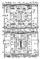
- the ski tuning device 20 itself is probably best seen in Figs. 3 through 10 to consist of a frame member 30, a pair of electric motors 32 operatively connected to driven grinding wheels 34, and a servo mechanism 36 for changing the disposition of the grinding wheels relative to the frame member 30 in a manner to be described in detail hereinafter.
- the frame member includes a pair of end walls 38, a pair of side walls 40 connected to the end walls, and a top wall 42.
- a pair of tubular members 44 interconnect the end walls near the center thereof and adjacent to the top edge of the end walls to form a handle that can be gripped by a user of the tuning device.
- the servo mechanism 36 includes a pair of slideable plates 46 (best seen in Fig. 10) which are disposed in a generally horizontal orientation when the device is positioned on the horizontal bottom surface of the inverted ski.
- the slideable plates 46 are generally rectangular in configuration having a pair of rectangular notches 48 formed in opposite ends along the outside edge 50 thereof for a purpose to be described later.
- a first pair of pins 52 extend longitudinally away from opposite ends of each slideable plate adjacent its inside edge 54, and a second pair of pins 56 extend longitudinally away from opposite ends of each slideable plate adjacent its outside edge 50 so as to be disposed within the notches 48.
- a pair of spring anchor brackets 58 protrude upwardly from the top surface of each slideable plate near the second pair of pins 56 and are adapted to anchor one end of a tension spring 60 to be described later.
- the driven shaft 64 of each motor has one of the grinding wheels 34 operatively connected thereto with the grinding wheel being composed of a material suitable for grinding the metal edges of the ski.
- the driven shaft of each motor extends perpendicularly to the slideable plate 46 so that when the plate is disposed in a horizontal orientation, the driven shaft 64 is disposed vertically and the grinding face 34G of the associated grinding wheel is disposed parallel to the plate 46 and facing downwardly.
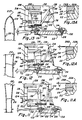
- each end wall 38 has a pair of horizontal slots 66 formed in its inner surface near the bottom edge 38B with the slots being longitudinally aligned with each other and opening through the outer side edges of the end wall.
- the first pair of pins 52 in each slideable plate 46 are adapted to be slideably received in an associated slot 66 whereby the slideable plate can be moved in a horizontal direction laterally of the frame member 30.
- the second pair of pins 56 of each slideable plate are adapted to ride in a cam slot 68 provided in a cam block 70 with the cam blocks also being seen in Fig. 10.
- the cam blocks 70 are essentially L-shaped in configuration having a horizontally disposed bead 72 protruding from an outside face which is adapted to be slideably received in one of the slots 66 in the end walls 38. There are four of the cam blocks, one for each slot 66. The inside face of each cam block has the cam slot 68 formed therein. It will be appreciated that the cam blocks can be moved laterally of the frame member 30 within the slots 66 provided in the end walls, and the slideable plates 46 can be moved laterally of the frame member independently of the cam blocks.
- the cam blocks 70 each have a threaded passage 74 through an upper portion thereof with the passage extending laterally of the frame member 30 and adapted to receive one end of a double reverse-threaded adjustment shaft 76.
- the ends of the adjustment shafts 76 are threadedly received in the threaded passages 74 of the cam blocks. It should be pointed out that the threads at opposite ends of the adjustment shafts are oppositely threaded so that rotation of the shaft will cause the cam blocks 70 to be simultaneously moved toward each other or simultaneously moved away from each other, depending upon the direction of rotation of the adjustment shaft.
- adjustment shafts are rotatably journaled in bearing blocks 78 protruding inwardly from the adjacent end wall 38, and handle members 80 are attached to opposite ends of the adjustment shafts to facilitate rotation of the shafts. Rotation of the shafts will thus effect movement of the cam blocks 70 along the guide slots 66 in the end walls.
- a centrally disposed, longitudinally extending guide rod 82 passes between the end walls 38 at the transverse center thereof and near the lower edge of the end walls so as to be substantially coplanar with the slideable plates 46.
- the guide rod 82 serves as a guide for a pair of guide link mechanisms 84.
- Each guide link mechanism includes a pair of link arms 86 pivotally connected at an inner end to a slide member 88 and pivotally connected at their outer ends to a downwardly projecting pin 90 from the bottom surface of the associated slideable plate 46 and adjacent to an end wall 38.
- the slide member 88 has a tubular sleeve slideably mounted on the guide rod with oppositely directed attachment arms pivotally connected to the inner ends of the link arms 86 as by a pivot pin.
- the slide member 88 also includes a downwardly extending attachment finger 92 disposed perpendicularly to the attachment arms and having means thereon for securing one end of a tension spring 94, which serves to bias the slide members 88 toward each other.
- the link arms 86 have openings 96 therethrough near their outer ends which are adapted to anchor opposite ends of a pair of tension springs 98, which also bias the slideable plates 46 in a horizontal direction towards each other.
- the previously mentioned tension springs 60 interconnect the slideable plates by being connected to the brackets 58 described previously as projecting upwardly from the slideable plates so that this pair of springs is disposed on the top side of the plates and again biases the plates in a horizontal direction towards each other.
- the tension springs are mounted both above and below the plates 46 encouraging the plates to slide smoothly in the guide slots 66 provided in the end walls by providing a substantially uniform pull from both above and below each plate.
- a gussetted angle iron mounting bracket 100 is secured to the bottom surface of each slideable plate 46 so as to extend longitudinally thereof.
- the bracket 100 supports a pair of guide rollers 102 in bearings 104 provided at opposite ends of the bracket with the rollers being adapted to rotate about a vertical axis.
- the guide rollers 102 protrude downwardly a slight distance further than the grinding wheels 34 so that the guide rollers can engage the sides of the ski 22 when the grinding wheel is in engagement with the bottom surface of the metal edges 26B.
- the guide rollers are laterally spaced a fixed distance from the centers of the grinding wheels so that the centers of the grinding wheels are vertically aligned with the inside edge of the associated metal edge when the guide rollers are engaged with the sides of the ski.
- the guide rollers will follow the contoured sides of the skis and move the slideable plates 46 inwardly and outwardly as the ski becomes narrower and wider respectively.
- the rollers 102 force the slideable plates horizontally outwardly against the bias placed on the plates by the various tension springs as the ski gets wider.
- the rollers also allow the plates to move horizontally inwardly toward each other under the bias of the various tension springs at locations along the ski where it is relatively narrow.
- the electric motors 32 which rotate the grinding wheels 34 and are securely mounted on the top side of the slideable plates 46 are electrically connected through a switchbox 106 to a power source via an electrical cord 108.
- the switchbox has an on/off toggle switch 110 so that when power is supplied to the switchbox, the motors can be energized or de-energized by manipulation of the toggle switch.
- each end wall 38 of the frame means has a depth adjustment bar 112 connected thereto with the depth adjustment bar serving to support the tuning device 20 on the bottom surface 22B of the ski.
- the tuning device 20 as the tuning device 20 is moved along the length of the ski, it slides along the bottom surface of the ski on the depth adjustment bars 112.
- Each depth adjustment bar is channel shaped and is slideably received on the bottom edge 38B of the associated end wall 38 for vertical adjustment.
- Adjustment screws 114 are threadably passed through each depth adjustment bar near opposite ends thereof so as to engage the bottom edge 38B of the associated end wall whereby the spacing of the depth adjustment bar from the bottom edge of the end wall can be regulated.
- Compression springs 116 are also operatively connected to opposite ends of the depth adjustment bars and the lower edges of the end walls 38 to bias the depth adjustment bars toward the lower edges of the end walls with the adjustment screws 114 counteracting the bias.
- the depth adjustment bars 112 are primarily utilized to adjust the spacing of the grinding surface 34G of the grinding wheels from the bottom surface 26B of the metal edge 26 on the ski so that the grinding wheels will grind the metal edges of the ski at a desired depth. This is particularly useful when the grinding surfaces 34G are worn down, as the depth adjustment bar can be adjusted so as to be closer to the bottom edge 38B of the end wall thereby bringing the grinding surface back into engagement with the metal edges 26.
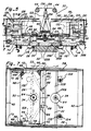
- the tuning device includes three sets of calibrated indicators best seen in Figs. 3, 5 and 11 through 13.
- the first set of indicators 118 advises the operator of the device as to the width of the ski
- the second set of indicators 120 advises the operator as to the angle of the grinding wheels 34 relative to the bottom of the ski 22B
- the third set 122 advises the operator as to the lateral location of the device 20 on the ski 22.
- the first set of indicators 118 consists of four vertical plates 124 each being mounted securely on the top surface of one of the cam blocks 70.
- Each vertical plate 124 has a pointed finger 126 adapted to cooperate with printed and calibrated linear measurement indicia 128 disposed on the inner surface of the associated end wall 38 whereby the pointed finger 126 will indicate on the printed indicia 128 the relative width of the ski.
- the guide rollers 102 are adapted to be advanced inwardly toward the sides of the ski by rotation of the adjustment shafts 76 which move the cam blocks 70 and concurrently the slideable plates 46 on which the guide rollers are mounted. Movement of the cam blocks moves the vertical plates 124 and the pointed finger 126 indicates on the calibrated indicia 128 the lateral separation of the rollers 102 and thus the width of the ski when the rollers are moved into engagement with the sides of the ski.
- Each vertical plate 124 also carries calibrated indicia 130 thereon set forth in degrees.
- the indicia 130 is adapted to cooperate with a second pointed finger 132, forming a part of the second set 120 of four indicators that is mounted on one end of a slideable plate 46.
- the calibrated indicia 130 is adapted to indicate the relative angle between the slideable plate and the bottom surface 22B of the ski. This angle is also the angle formed between the bottom grinding surface 34G of the associated grinding wheel and the bottom surface of the ski.
- the pointed finger 132 will move relative to the calibrated indicia 130 on the vertical plate 124 relating to degrees to indicate the relative angle between the grinding surface 34G and the bottom surface of the ski.
- the third set of indicators 122 on the device 20 relates to a system for maintaining the device in a laterally centered relationship with the ski and includes two pair of indicator link arms 134 with a pair being disposed at each end of the device.
- the lower ends of the link arms 134 are each pivotally mounted on one of the first pair of pin members 52 protruding from each end of the slideable plates 46.
- the upper ends of the link arms 134 are pivotally connected to each other by a pivot pin and have a notch 136 defined therebetween which can be aligned with a vertical center line indicator 138 inscribed on the inner surface of the associated end wall 38.
- the notch 136 formed at the upper end of the pair of link arms 134 will be aligned with the associated center line indicator 138, but should the tuning device be moved laterally of the ski so that it is not centered thereon, the notch 136 at the upper end of the link arms will be moved to one side or the other of the center line to advise the operator that the device is no longer centered on the ski.
- a ski 22 is first inverted and secured in any suitable manner such as on the support blocks shown in Figs. 1 and 2, so that the bottom surface 22B of the ski forms a substantially horizontal plane.
- the tuning device 20 is then placed on the ski at approximately its longitudinal center where the ski has its narrowest width.
- the guide rollers 102 have to be spaced a greater distance apart than the width of the ski, and this can be accomplished through rotation of the adjustment shafts 76.
- the adjustment shafts can again be rotated in an opposite direction to advance the guide rollers inwardly into engagement with the sides of the ski.
- the guide rollers move laterally upon rotation of the adjustment shafts since the cam blocks 70 move inwardly toward each other with rotation of the adjustment shafts until the guide pins 56 on the slideable plates 46, which are disposed in the cam slots 68 of the cam blocks, are engaged by one end of the cam slots, forcing the plates 46 to slide inwardly.
- the plates 46 will slide inwardly until the guide rollers 102, which are mounted on the slideable plates, engage and thus sense the sides of the ski.
- the width of the ski can be read on the first calibrated scale 128 so that the operator knows what size ski he is tuning.
- the electric motors 32 are energized by switching the toggle switch 110 to its "on" position, which initiates a rotation of the grinding wheels 34.
- the tuning device can then be moved longitudinally of the ski while maintaining the depth guide adjustment bars 112 in engagement with the bottom surface of the ski so that the grinding wheels slide along the bottom surface 26B of the metal edges 26 which are in vertical alignment therewith.
- the guide rollers are moved along opposite contoured sides of the ski, and the ski widens near the leading and trailing ends thereof, the guide rollers are forced away from each other, thus forcing the slideable plates 46 to move away from each other whereby the second pair of pins 56 on each plate, which are disposed in the cam slots 68 are forced downwardly in the cam slots, causing the associated slideable plate to pivot slightly about its first pair of pin members 52.
- the lower longitudinal grinding surfaces 34G on the grinding wheels are also tilted accordingly and grind a beveled surface on the metal edges of the ski. The greater the width of the ski, the greater the bevel, due to the fact that the further the slideable plates are moved laterally outwardly, the greater the degree of pivot.
- the angular relationship between the bottom surface 22B of the ski and the slideable plates 46, and thus the grinding wheels 34, are indicated on the second calibrated indicia 130 whereby the operator can visually determine the amount of bevel that is being placed on the metal edges of the ski.
- the angle of the grinding wheels should be set to .5 degrees.
- the electric motors 32 can be energized to operate the grinding wheels and the device then moved along the length of the ski.
- the bevel at the narrowest part of the ski was .5 degrees
- the bevel at the widest part, as seen in Fig. 13A would automatically be ground at approximately 1.5 degrees.
- the bevel at the narrowest part of the ski can be preselected as desired so that if this bevel was selected to be 1 degree, for example as shown in Fig. 12A, the bevel at the widest part of the ski would automatically be ground to approximately 2 degrees.
- the bevel will vary smoothly in accordance with the varying width of the ski.
Landscapes
- Engineering & Computer Science (AREA)
- Mechanical Engineering (AREA)
- Grinding And Polishing Of Tertiary Curved Surfaces And Surfaces With Complex Shapes (AREA)
- Silicon Polymers (AREA)
- Footwear And Its Accessory, Manufacturing Method And Apparatuses (AREA)
- Cleaning Of Streets, Tracks, Or Beaches (AREA)
- Finish Polishing, Edge Sharpening, And Grinding By Specific Grinding Devices (AREA)
Claims (14)
- Abstimmvorrichtung zum Schleifen der unteren Kante (26) eines Skis (22), der eine variable Breite auf seiner Länge hat, mit einer Rahmeneinrichtung (30), die über der Länge des Skis (22) bewegt werden kann, einer Schleifeinrichtung (34), die an der Rahmeneinrichtung (30) betrieblich befestigt ist, und einer Einrichtung zum Verändern des Winkels der Schleifeinrichtung (34) relativ zu der Unterseite (22B) des Skis (22), gekennzeichnet durch eine Servomechanismuseinrichtung (36) an der Rahmeneinrichtung (30), die der Schleifeinrichtung betrieblich zugeordnet ist, und eine Erfassungseinrichtung aufweist zum Erfassen der Breite des Skis (22) und eine automatische Einrichtung zum Einstellen des Winkels der Schleifeinrichtung (34) in einer direkten Beziehung zu der Breite des Skis (22), die durch die Erfassungseinrichtung erfaßt wird.
- Vorrichtung nach Anspruch 1, dadurch gekennzeichnet, daß die Erfassungseinrichtung eine Abtasteinrichtung (102) aufweist, die längs entgegengesetzter Seiten des Skis (22) bewegt wird, wenn die Rahmeneinrichtung (30) über der Länge des Skis (22) bewegt wird.
- Vorrichtung nach Anspruch 2, dadurch gekennzeichnet, daß eine verschiebbare Platteneinrichtung (46) an der Rahmeneinrichtung (30) betrieblich befestigt ist, wobei die Abtasteinrichtung (102) an der verschiebbaren Platteneinrichtung (46) betrieblich befestigt ist, und daß die Schleifeinrichtung (34) mit der verschiebbaren Platteneinrichtung (46) zur Bewegung mit derselben betrieblich verbunden ist, wodurch die Schleifeinrichtung (34) veranlaßt wird, der Kante (26) des Skis (22) zu folgen, wenn die Rahmeneinrichtung (30) über der Länge des Skis (22) bewegt wird.
- Vorrichtung nach Anspruch 3, dadurch gekennzeichnet, daß eine Steuereinrichtung (56, 68, 70) an der Rahmeneinrichtung (30) vorgesehen und der verschiebbaren Platteneinrichtung (46) betrieblich zugeordnet ist, um den Winkel der Platteneinrichtung (46) und der Schleifeinrichtung (34) relativ zu der unteren Oberfläche (22B) des Skis (22) zu ändern, wenn die Rahmeneinrichtung (30) über der Länge des Skis (22) bewegt wird und die Abtasteinrichtung (102) die sich verändernde Breite des Skis (22) erfaßt.
- Vorrichtung nach Anspruch 4, gekennzeichnet durch eine nachgiebige widerstandsfähige Vorspanneinrichtung (60, 94, 98) zum Halten der Abtasteinrichtung (102) in Berührung mit den Seiten des Skis (22).
- Vorrichtung nach Anspruch 5, dadurch gekennzeichnet, daß die Steuereinrichtung (56, 68, 70) einen größeren Winkel zwischen der verschiebbaren Platteneinrichtung (46) und der Unterseite (22B) des Skis (22) an Stellen hervorruft, wo der Ski (22) relativ breit ist, als an Stellen, wo der Ski relativ schmal ist.
- Vorrichtung nach Anspruch 6, gekennzeichnet durch eine geeichte Anzeigeeinrichtung (120, 130, 132) zum Anzeigen des relativen Winkels zwischen der verschiebbaren Platteneinrichtung (46) und der Unterseite (22B) des Skis (22).
- Vorrichtung nach Anspruch 7, dadurch gekennzeichnet, daß die Rahmeneinrichtung (30) zwei Endwände (38) hat, wobei in jeder Endwand (38) ein Paar Nuten (66) vorgesehen ist, und daß die verschiebbare Platteneinrichtung (46) aus zwei Plattenteilen (46) besteht, die eine erste Stifteinrichtung (52) an ihren entgegengesetzten Enden haben, welche in den Nuten (66) aufgenommen sind, so daß die Plattenteile (46) längs der Nuten (66) verschoben und außerdem um die ersten Stifteinrichtungen (52) geschwenkt werden können.
- Vorrichtung nach Anspruch 8, dadurch gekennzeichnet, daß die Steuereinrichtung (56, 68, 70) aus zwei Paaren von Blockteilen (70) besteht, die an den Endwänden (38) nahe den Plattenteilen (46) betrieblich befestigt sind und jeweils eine Steuernut (68) haben, die einen Winkel mit den Nuten (66) in den Endwänden (38) bildet, wobei die Plattenteile (46) zweite Stifteinrichtungen (56) haben, die mit den Steuernuten (68) zusammenwirken, um die Plattenteile (46) zu veranlassen, um die ersten Stifteinrichtungen (52) zu schwenken, wenn sich die ersten Stifteinrichtungen (52) längs der Nuten (66) in den Endwänden (38) verschieben.
- Vorrichtung nach Anspruch 9, dadurch gekennzeichnet, daß die Blockteile (70) relativ zu den Endwänden (38) bewegbar sind, um die verschiebbaren Platteneinrichtungen (46) zu veranlassen, sich in einer reversierbaren lateralen Richtung relativ zu dem Ski (22) zu bewegen.
- Vorrichtung nach Anspruch 10, gekennzeichnet durch eine Vorspanneinrichtung (60, 94, 98) zum Drängen der Plattenteile (46) in Richtung aufeinanderzu in einer lateralen Richtung relativ zu dem Ski (22), um die Abtastteile (102) in Berührung mit den Seiten des Skis (22) zu halten.
- Vorrichtung nach Anspruch 11, dadurch gekennzeichnet, daß die Schleifeinrichtung (34) aus zwei Schleifrädern (34) besteht, die jeweils einem der Plattenteile (46) zugeordnet sind.
- Vorrichtung nach Anspruch 12, dadurch gekennzeichnet, daß jedes Schleifrad (34) eine untere Schleiffläche hat, die in einer Ebene bleibt, welche zu dem Plattenteil (46), dem es zugeordnet ist, parallel ist.
- Vorrichtung nach Anspruch 1, dadurch gekennzeichnet, daß die Motoreinrichtung (32), die mit der Schleifeinrichtung (34) gekuppelt ist, an der Rahmeneinrichtung (30) befestigt ist.
Priority Applications (1)
| Application Number | Priority Date | Filing Date | Title |
|---|---|---|---|
| AT87903162T ATE82537T1 (de) | 1986-05-09 | 1987-04-22 | Selbsttaetige anordung zum einstellen von skiern. |
Applications Claiming Priority (2)
| Application Number | Priority Date | Filing Date | Title |
|---|---|---|---|
| US861604 | 1986-05-09 | ||
| US06/861,604 US4679356A (en) | 1986-05-09 | 1986-05-09 | Automatic ski tuning device |
Publications (3)
| Publication Number | Publication Date |
|---|---|
| EP0267240A1 EP0267240A1 (de) | 1988-05-18 |
| EP0267240A4 EP0267240A4 (de) | 1990-02-22 |
| EP0267240B1 true EP0267240B1 (de) | 1992-11-19 |
Family
ID=25336258
Family Applications (1)
| Application Number | Title | Priority Date | Filing Date |
|---|---|---|---|
| EP87903162A Expired EP0267240B1 (de) | 1986-05-09 | 1987-04-22 | Selbsttätige anordung zum einstellen von skiern |
Country Status (5)
| Country | Link |
|---|---|
| US (1) | US4679356A (de) |
| EP (1) | EP0267240B1 (de) |
| AT (1) | ATE82537T1 (de) |
| DE (1) | DE3782722T2 (de) |
| WO (1) | WO1987006868A1 (de) |
Families Citing this family (13)
| Publication number | Priority date | Publication date | Assignee | Title |
|---|---|---|---|---|
| DE4413935C2 (de) * | 1994-04-21 | 1996-05-30 | Willi Leweke | Skikanten-Schleifgerät |
| AT409090B (de) * | 1996-07-25 | 2002-05-27 | Wintersteiger Gmbh & Co | Vorrichtung zum nachbearbeiten einer stahlkante eines skis |
| US20030186631A1 (en) * | 2002-03-29 | 2003-10-02 | Toyoda Koki Kabushiki Kaisha | Cylindrical grinder, and mechanism for producing relative movement between grinding wheel and workpiece in cylindrical grinder |
| US6702656B1 (en) | 2002-09-16 | 2004-03-09 | Edgetune, Inc. | Snow ski and snowboard edge sharpening device |
| AT413802B (de) * | 2004-01-30 | 2006-06-15 | Wintersteiger Gmbh & Co | Vorrichtung zum nachbearbeiten einer stahlkante eines skis |
| US8152596B2 (en) * | 2008-08-22 | 2012-04-10 | Universal Scientific Industrial (Shanghai) Co., Ltd. | Apparatus for deburring boards |
| NO329601B1 (no) * | 2009-02-13 | 2010-11-22 | Svein Iversbakken | Anordning for sliping av saler pa ski |
| US10905938B2 (en) * | 2014-07-22 | 2021-02-02 | Durell Laboratories, Inc. | Portable ski and snowboard edge sharpener and method of using the same |
| FR3033255A1 (fr) * | 2015-03-04 | 2016-09-09 | Jean Pierre Bocquet | Dispositif d'affutage simultane des carres inferieures et laterales de ski par disque abrasif |
| US10150196B2 (en) * | 2016-08-10 | 2018-12-11 | The Boeing Company | Method and automated rover device for surface treatment |
| AT523052B1 (de) * | 2019-11-22 | 2021-05-15 | Wintersteiger Ag | Verfahren zur Steuerung einer Vorrichtung zum Nachschleifen einer Stahlkante eines Skis |
| IT202200012890A1 (it) * | 2022-06-17 | 2023-12-17 | Nicola Carletti | Dispositivo portatile per la lavorazione e/o l’ispezione di una superficie di uno sci o simile. |
| CN115179133B (zh) * | 2022-08-18 | 2024-12-13 | 嘉兴量创科技有限公司 | 一种具有金属管道端口除锈功能的打磨装置 |
Family Cites Families (9)
| Publication number | Priority date | Publication date | Assignee | Title |
|---|---|---|---|---|
| US3159951A (en) * | 1961-04-14 | 1964-12-08 | Alois P Winbauer | Ski sharpening tool |
| US3412508A (en) * | 1966-02-16 | 1968-11-26 | Liguori J. Schell Jr. | Ski sharpener |
| US3585760A (en) * | 1969-06-30 | 1971-06-22 | Stanley M Richmond | Portable ski sharpener |
| US3899942A (en) * | 1974-06-14 | 1975-08-19 | Wilburn F Bradbury | Ski edge sharpener |
| US4030382A (en) * | 1976-03-01 | 1977-06-21 | C O Oberg & Co Ab | Sharpening device for steel ski edge strips |
| DE2653944A1 (de) * | 1976-11-27 | 1978-06-01 | Christian Fendt | Werkzeug zum nachbearbeiten von metallskikanten |
| US4442636A (en) * | 1982-01-22 | 1984-04-17 | Obland Donald R | Dual head edge sharpening device for skis |
| CH649928A5 (fr) * | 1982-12-09 | 1985-06-28 | Michel Hofstetter | Dispositif pour le finissage des carres de skis. |
| DE3341062A1 (de) * | 1983-11-12 | 1985-05-23 | Werner 7547 Wildbad Genth | Geraet zum be- bzw. nacharbeiten der stahlkanten von schiern |
-
1986
- 1986-05-09 US US06/861,604 patent/US4679356A/en not_active Expired - Fee Related
-
1987
- 1987-04-22 DE DE8787903162T patent/DE3782722T2/de not_active Expired - Fee Related
- 1987-04-22 WO PCT/US1987/000930 patent/WO1987006868A1/en not_active Ceased
- 1987-04-22 AT AT87903162T patent/ATE82537T1/de not_active IP Right Cessation
- 1987-04-22 EP EP87903162A patent/EP0267240B1/de not_active Expired
Also Published As
| Publication number | Publication date |
|---|---|
| DE3782722D1 (de) | 1992-12-24 |
| DE3782722T2 (de) | 1993-04-01 |
| US4679356A (en) | 1987-07-14 |
| EP0267240A4 (de) | 1990-02-22 |
| WO1987006868A1 (en) | 1987-11-19 |
| ATE82537T1 (de) | 1992-12-15 |
| EP0267240A1 (de) | 1988-05-18 |
Similar Documents
| Publication | Publication Date | Title |
|---|---|---|
| EP0267240B1 (de) | Selbsttätige anordung zum einstellen von skiern | |
| US5601473A (en) | Skate sharpening apparatus and method | |
| CA2984599C (en) | Blade sharpening system and method of using the same | |
| US20140335765A1 (en) | Adjustable sharpening apparatus and method for cutting implements | |
| US4066250A (en) | Ski clamping apparatus | |
| US3827185A (en) | Ice skate sharpening apparatus | |
| US2563018A (en) | Ice skate grinding machine | |
| CA2023121C (en) | Apparatus for sharpening the blade of a skate | |
| US4732056A (en) | Saw chain grinding machine | |
| EP0318207A2 (de) | Messerhalter in einer Vorrichtung zur Herstellung von Passepartouts | |
| US4294043A (en) | Ice skate sharpener | |
| US20040053565A1 (en) | Snow ski and snowboard edge sharpening device | |
| US4750537A (en) | Universal golf wood facing machine and method | |
| US4241544A (en) | Skate blade sharpener | |
| US4172343A (en) | Ice skate sharpener | |
| EP4061575B1 (de) | Verfahren zur steuerung einer vorrichtung zum nachschleifen einer stahlkante eines skis | |
| EP1178870A1 (de) | Schärfen von schlittschuhlaufeisen | |
| US7530879B2 (en) | Apparatus for reworking a steel edge of a ski | |
| US5701787A (en) | Sharpening guide for snowboards and alpine skis | |
| US6805622B1 (en) | Ski sharpening arrangement | |
| US5643066A (en) | Fixture for ski edge finishing tool | |
| US4069620A (en) | Ice skate sharpener | |
| US2897640A (en) | Portable knife sharpener | |
| US2769283A (en) | Abrading machine for tire tread surfaces | |
| DE7207209U (de) | Maschine zum Schleifen der Beläge bzw. Kanten von Wintersportgeräten |
Legal Events
| Date | Code | Title | Description |
|---|---|---|---|
| PUAI | Public reference made under article 153(3) epc to a published international application that has entered the european phase |
Free format text: ORIGINAL CODE: 0009012 |
|
| AK | Designated contracting states |
Kind code of ref document: A1 Designated state(s): AT CH DE FR IT LI |
|
| 17P | Request for examination filed |
Effective date: 19880516 |
|
| A4 | Supplementary search report drawn up and despatched |
Effective date: 19900222 |
|
| 17Q | First examination report despatched |
Effective date: 19910802 |
|
| RAP3 | Party data changed (applicant data changed or rights of an application transferred) |
Owner name: THOMAS, JACQUES, R. |
|
| GRAA | (expected) grant |
Free format text: ORIGINAL CODE: 0009210 |
|
| AK | Designated contracting states |
Kind code of ref document: B1 Designated state(s): AT CH DE FR IT LI |
|
| REF | Corresponds to: |
Ref document number: 82537 Country of ref document: AT Date of ref document: 19921215 Kind code of ref document: T |
|
| ET | Fr: translation filed | ||
| REF | Corresponds to: |
Ref document number: 3782722 Country of ref document: DE Date of ref document: 19921224 |
|
| ITF | It: translation for a ep patent filed | ||
| PLBE | No opposition filed within time limit |
Free format text: ORIGINAL CODE: 0009261 |
|
| STAA | Information on the status of an ep patent application or granted ep patent |
Free format text: STATUS: NO OPPOSITION FILED WITHIN TIME LIMIT |
|
| 26N | No opposition filed | ||
| PGFP | Annual fee paid to national office [announced via postgrant information from national office to epo] |
Ref country code: FR Payment date: 19950313 Year of fee payment: 9 Ref country code: CH Payment date: 19950313 Year of fee payment: 9 |
|
| PGFP | Annual fee paid to national office [announced via postgrant information from national office to epo] |
Ref country code: AT Payment date: 19950314 Year of fee payment: 9 |
|
| PGFP | Annual fee paid to national office [announced via postgrant information from national office to epo] |
Ref country code: DE Payment date: 19950324 Year of fee payment: 9 |
|
| PG25 | Lapsed in a contracting state [announced via postgrant information from national office to epo] |
Ref country code: AT Effective date: 19960422 |
|
| PG25 | Lapsed in a contracting state [announced via postgrant information from national office to epo] |
Ref country code: LI Effective date: 19960430 Ref country code: CH Effective date: 19960430 |
|
| REG | Reference to a national code |
Ref country code: CH Ref legal event code: PL |
|
| PG25 | Lapsed in a contracting state [announced via postgrant information from national office to epo] |
Ref country code: FR Effective date: 19961227 |
|
| PG25 | Lapsed in a contracting state [announced via postgrant information from national office to epo] |
Ref country code: DE Effective date: 19970101 |
|
| REG | Reference to a national code |
Ref country code: FR Ref legal event code: ST |
|
| PG25 | Lapsed in a contracting state [announced via postgrant information from national office to epo] |
Ref country code: IT Free format text: LAPSE BECAUSE OF NON-PAYMENT OF DUE FEES;WARNING: LAPSES OF ITALIAN PATENTS WITH EFFECTIVE DATE BEFORE 2007 MAY HAVE OCCURRED AT ANY TIME BEFORE 2007. THE CORRECT EFFECTIVE DATE MAY BE DIFFERENT FROM THE ONE RECORDED. Effective date: 20050422 |