EP0266722B1 - Method and apparatus for sowing individual seeds in a furrow - Google Patents
Method and apparatus for sowing individual seeds in a furrow Download PDFInfo
- Publication number
- EP0266722B1 EP0266722B1 EP87116083A EP87116083A EP0266722B1 EP 0266722 B1 EP0266722 B1 EP 0266722B1 EP 87116083 A EP87116083 A EP 87116083A EP 87116083 A EP87116083 A EP 87116083A EP 0266722 B1 EP0266722 B1 EP 0266722B1
- Authority
- EP
- European Patent Office
- Prior art keywords
- funnel
- housing
- seed
- seeds
- dispensing
- Prior art date
- Legal status (The legal status is an assumption and is not a legal conclusion. Google has not performed a legal analysis and makes no representation as to the accuracy of the status listed.)
- Expired - Lifetime
Links
Images

Classifications
-
- A—HUMAN NECESSITIES
- A01—AGRICULTURE; FORESTRY; ANIMAL HUSBANDRY; HUNTING; TRAPPING; FISHING
- A01C—PLANTING; SOWING; FERTILISING
- A01C7/00—Sowing
- A01C7/20—Parts of seeders for conducting and depositing seed
-
- A—HUMAN NECESSITIES
- A01—AGRICULTURE; FORESTRY; ANIMAL HUSBANDRY; HUNTING; TRAPPING; FISHING
- A01C—PLANTING; SOWING; FERTILISING
- A01C7/00—Sowing
- A01C7/20—Parts of seeders for conducting and depositing seed
- A01C7/206—Seed pipes
-
- A—HUMAN NECESSITIES
- A01—AGRICULTURE; FORESTRY; ANIMAL HUSBANDRY; HUNTING; TRAPPING; FISHING
- A01C—PLANTING; SOWING; FERTILISING
- A01C7/00—Sowing
- A01C7/04—Single-grain seeders with or without suction devices
- A01C7/042—Single-grain seeders with or without suction devices using pneumatic means
Definitions
- the invention relates to a method for sowing individual seeds in a furrow drawn by a coulter, in which the individual seeds are guided in a guide device, caught in the area of the coulter, temporarily stored and then released into the furrow.
- the invention also shows a seeding device with a separating device for the seeds, a guide device and a coulter, wherein in the coulter in the area of the end of the guide device a device for collecting the seeds moved in the guide device and for depositing the seeds into the furrow drawn by the coulter is provided.
- a method and a device of the type described in the opening paragraph are known from US-A-3,303,801.
- the semen comes from a separating device into a guide device designed as a downpipe, in which it is guided downwards.
- a device for collecting the moving seeds Arranged below the end of the downpipe is a device for collecting the moving seeds, which essentially consists of a V-shaped curved collecting trough, which is assigned a fixedly arranged scraper.
- the V-shaped collecting trough is arranged to reciprocate relative to the stripper and is driven synchronously with the separating device.
- the collecting trough remains under the end of the guide device until at least two seeds have been collected and temporarily stored. This seed is then released to fall into the furrow by the relative movement between the collecting trough and the scraper.
- the seed is always brought into the furrow in several clumps in free fall. Since the V-shaped collecting trough is open at the top and front, there is There is a danger that the seeds will jump when they hit the collecting trough or when they hit grains that are already in the collecting trough, i.e. they will fall next to the trough at an undesired point in time, so that they will be deposited in the nest with a corresponding number and the cracked grain on the Distance between two neighboring clumps is deposited somewhere. There is also a risk of rolling in the furrow if the seeds are deposited in free fall.
- the seeds collected in the collecting trough are generally released one after the other in free fall, the dropping being carried out in such a way that the individual seeds still have a movement component in the direction of travel which corresponds to the driving speed of the seeder.
- the device for collecting and temporarily storing the seeds is designed here purely mechanically, so that corresponding wear and contamination problems can also occur.
- EP-A-37 775 shows a seeding device with a perforated disc on which the seeds are pneumatically separated by means of negative pressure.
- a venturi tube is provided at a transfer point for the separated seeds, which has an opening at the transfer point for the entry of the seeds from the perforated disc into the venturi tube and which is connected to a compressed air source.
- the inclination of the axis of the Venturi tube can be adapted to the driving speed of the seeding device so that the individual seed is accelerated vertically downwards and deposited by the compressed air. There is no intermediate storage of the seed after the perforated disc. The single seed is thus thrown off at a comparatively high altitude.
- GB-A-937 519 shows a method for sowing separated seeds in a device in which the seed is first separated with a cell wheel and then in the separated form is successively fed to a guide device in the form of an inclined downpipe.
- This downpipe opens into a funnel-shaped part and continues in a further downpipe section.
- a continuous or pulsating air flow is added in the funnel-shaped part in order in this way to additionally accelerate the individual, spaced seeds in the downpipe.
- Errors or irregularities in the separating device as well as different paths in the downpipe due to uneven friction are only increased by the compressed air acceleration, so that the placement accuracy, i.e. compliance with the seeding distance, primarily depends on the correct functioning of the separating device and the following conditions, e.g. B. the friction in the downpipe is dependent.
- a funnel is provided which merges into a pair of expanding jaws with a funnel-shaped recess.
- the funnel-shaped recess indicates a hole smaller than the smallest grain at its lower end.
- An annular air gap is arranged between the funnel and the pair of expanding jaws, through which an air flow is introduced into the funnel and the funnel-shaped recess. If there are now several grains in the funnel or the funnel-shaped recess, these are blown up to a certain height into the funnel by the air flow apart from a single one that comes to lie in front of the bore. By briefly opening the expanding jaws, the individual grain lying in front of the hole is released.
- a device which represents a further development of the device according to DE-A-28 47 514.
- a blowpipe is provided as a further component, which directs an air flow towards the bore, while the annular gap ceases to exist.
- the air flow accelerates the individual grain when opening the expanding jaws just more likely that the expanding jaws can be closed before the remaining grains pass through the opening.
- a reliable mode of operation of the device is only achieved by an additional ejector for the individual grain or retention measures for the remaining grains. Because of the short acceleration distances alone, there can be no question of significant acceleration. The acceleration takes place over the length of the bore, which extends only through the wall of a housing.
- GB-A-593 983 shows a device with a suction and blowing head which is cyclically moved in an elliptical path on a gooseneck, this suction head being immersed with an opening in a seed supply, a single one Suck the seed horn, promote it as it moves upwards and release it in the upper region above the opening of a downpipe, during which the suction flow is alternately converted into a pressure flow, which is done with the aid of a bellows.
- a guide device namely a downpipe. The seed falls through the guide device in accordance with the working accuracy of the separating device.
- DE-OS 34 41 703 shows a precision seed drill with a chamber wheel, in which a guide trough which receives the seeds is provided for guiding and centering the continuous seeds in the chamber walls of the chamber wheel and / or in the housing thereof. A centering effect takes place through this guide trough. This centering effect is, however, achieved in the area of the separating device, from which the individual seeds pass freely into the furrow.
- DE-OS 27 11 464 shows a device for separating and sowing seeds that are presented or processed in a suspension.
- the individual seeds are held in the area of the separating device by a suction flow in front of a nozzle until the remaining seeds have been washed away. Then this seed is emitted by two flow impulses, which are directed transversely to one another, into a downward guiding device, from which it goes directly into the furrow.
- the invention has for its object to improve the placement accuracy of individual seeds to each other in a method and an apparatus of the type described above, so that the sowing distance of individual seeds in the row is maintained more precisely, in this way the sowing pattern with respect to the sowing distance to optimize and to achieve an increase in yield in accordance with the conditions for the respective seed type.
- this is achieved in the method of the type described at the outset in that the individual seed is temporarily stored when it is caught, point-wise to an axis corresponding to the direction of release and with centering action, and that the individual seed is accelerated from its temporarily idle position by a brief fluid surge in the direction of release the furrow is released. It is important first of all that the individual seeds, that is to say only one seed at a time, are temporarily stored at the same point in a centered manner about an axis corresponding to the direction of release. The individual seed therefore always rests at the same place. This point is fixed at a point, no longer linear.
- the individual seed is always accelerated in the same way from the same point and released into the furrow. Since the rest position of the seed is comparatively deep, especially in the interior of the coulter, the drop height or discharge height is low. Over this short distance, not only does gravity act, but also the intermittent fluid surge on the individual seeds, so that this is released into the furrow at an accelerated rate. This also results in a better embedding of the individual seed at the point of impact in the soil combined with the advantage of a better connection to the capillary system for the soil moisture. This is particularly the case if water, a nutrient solution or the like is used as the fluid.
- sowing distance does not depend on the working accuracy of the separating device is more dependent.
- the pressure of the fluid can be variably adjusted and adapted to the respective type of seed.
- the time span of the action of the brief burst of fluid can also be made variably adjustable in order in this way to also determine the amount of a nutrient or fertilizer solution for the individual seeds.
- Air can be used as the fluid. This has the advantage that this fluid does not have to be carried in separate containers, but is available in practically unlimited quantities.
- a liquid as the fluid. In addition to water, this may also contain a nutrient solution, pickling agent, weed or pest protection, vaccine, fertilizer, germ promoter or germ inhibitor.
- rhizobia germs can be used as inoculants.
- Germ promoters and / or germination inhibitors are also useful, for example, in their joint application on different, related sowing devices when seeds of two different types are to be sown together, in which case the exact adherence to the sowing pattern of the seeds or plants is important and by favoring them or delay in germination should be influenced on the growing conditions and the harvesting conditions.
- a jet of liquid is used as a fluid surge, the individual seed is embedded in a substrate solidified with it, and the result is that the capillary system provides more moisture for the swelling and germination of the seed, which is advantageously noticeable in a more uniform emergence and germination.
- weed control can also be set variably and can be carried out in particular around the individual seed or the crop. Due to the fluid surge, the intermediate storage location is continuously cleaned.
- the sowing device for carrying out the method is characterized according to the invention in that the device for collecting and dispensing the individual seed is set up, has an axial, essentially closed housing and is funnel-shaped for centering the individual seed relative to the axis of the housing in accordance with the dispensing direction, that the funnel-shaped part of the housing can be moved into a position in which it catches and holds the individual seeds and optionally in a second position in which it releases the individual seeds, and that a pulsating fluid source is connected to the housing of the device is.
- the device for collecting and dispensing is not set up for several seeds simultaneously or in succession, but rather only for a single seed. This makes it possible to temporarily store every single seed at a specific point.
- a funnel-shaped design of the housing at its lower end is particularly important, that is to say with a funnel whose tip points downward in the dispensing direction.
- Such a funnel-shaped configuration is understood to mean a configuration that tapers downward in some way, which can also exist as a truncated cone, truncated pyramid or a section of hose or the like that narrows in diameter.
- This funnel can be open or closed at its lower end.
- the funnel-shaped part of the housing is designed in its first position so that it catches the individual seeds, centers them and always holds them in the same place. In the second position, in which the funnel-shaped part of the housing is either controlled independently or is also guided by the fluid surge, the individual seed is accelerated out of the same position.
- a surge of fluid can, for. B. control by using solenoid valves at extremely precise intervals, so that the placement accuracy and the sowing distance is significantly improved.
- the funnel-shaped part of the housing can be actuated into the two positions by the pulsating fluid source. In this case, a separate control and movement of the funnel-shaped part of the housing is unnecessary.
- the funnel-shaped part of the housing only has to either consist of several rigid but movably mounted parts or be designed to be elastically flexible overall, as is the case, for. B. is a truncated cone-shaped funnel made of rubber or the like.
- the housing of the device for catching and dispensing the individual seed can be essentially cylindrical and aligned with the axis of the cylinder in the dispensing direction.
- the cylindrical housing has an opening on the side for the passage of the seed out of the guide device and the fluid source is connected to the upper end of the cylindrical housing, while the funnel-shaped intermediate storage point is arranged in the lower region.
- the axis of the cylindrical housing thus determines the direction of discharge. It is entirely possible to adapt the axis of the housing to the driving speed and to change its inclination accordingly in the end, the single seed is placed in the furrow of the flock, accelerated vertically downwards. So that the individual seeds reach the cylindrical housing through the guide device and are deposited in a point-centered manner, the action of gravity is generally sufficient.
- the housing of the device for catching and dispensing can have a solenoid valve and a nozzle for generating the short-term fluid surges in the area of the connection of the fluid source.
- solenoid valves With such solenoid valves, the cycle times of the fluid surges can be controlled very precisely.
- a defined flow is created by a nozzle, so that identical acceleration conditions are always given with regard to the seed which is temporarily stored and aligned.
- the funnel-shaped intermediate storage point can have elastically resilient or pivotable mounted wall parts or such a wall under pressure.
- the funnel-shaped wall or the wall parts can be made from pyramid-like metal pieces, from a hose-like rubber body, from wire or fabric pieces or the like, and a return spring, e.g. B. a rubber ring exist.
- the return to the closed or catching position of the funnel-shaped Wall parts can be made solely by the action of a weight, but also by using springs.
- the funnel-shaped wall or the wall parts are expediently interchangeably arranged on the device for catching and dispensing, in order to take into account any wear that may occur and, on the other hand, to enable a respective adaptation to the size and type of the seed.
- a control device for the synchronous control of the separating device on the one hand and the device for catching and dispensing the individual seed on the other hand is provided in order to adapt the individual units to one another in terms of their working speed.
- the control device can be designed for the time-variable delivery of the fluid surges, the variation of course only working sensibly within the division of the separating device. But it is quite possible, for. B. to form two different seeding intervals one after the other in a row, even though the separating device works with constant pitch.
- the separating device upstream of the device for catching and dispensing the individual seeds can be driven via stepper motors controlled by the control device, so that the separating device delivers the individual seeds in the correct cycle in each case.
- the housing of the device for catching and dispensing can have a constriction in the area of the funnel-shaped wall or upstream of it, in order to specifically shape the flow of the fluid at this point.
- sowing units of this type can also be provided offset from one another and / or one behind the other on a seed drill.
- Such a seeder is suitable for sowing corn, beans, sugar beets, cereals and the like. The like.
- Mixed sowing from seeds of different types is also possible, whereby each sowing unit is of course only matched to the seeds of one type.
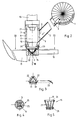
- Each sowing unit has a separating device (1) which can be of any design, for example as a cellular wheel (2). It is essential that the individual seeds (3) are made available in isolated form if the cell wheel (2) according to Arrow (4) is driven.
- the individual seeds arrive in cycles at a delivery point at the separating device (1), to which a guide device (5), usually in the form of a downpipe, is connected.
- a device for catching and dispensing (7) the individual seed (3) is provided, which essentially consists of a cylindrical housing (8) which has a laterally arranged opening (9) for The individual seed (3) passes from the guide device (5) into the interior (10) of the cylindrical housing.
- the cylindrical housing (8) is arranged with its axis (11) in the discharge direction of the individual seed (3) into the furrow (12). This dispensing direction and thus the axis (11) can be changed in its angle and adjusted so that it is adapted to the working speed of the seeder.
- a fluid line (14) is connected to the upper end of the housing (8) via an electrically controllable injection valve (13), on which fluid, ie air or liquid, is present under pressure. Fluid shocks can thus be intermittently released into the housing (8) via the injection valve (13).
- the housing (8) is equipped with funnel-shaped wall parts (15) or such a funnel-shaped wall, which in any case narrow downwards in the direction of ejection and can be open or closed there.
- FIG. 1 Such a funnel-shaped wall part (15) made of rubber or rubber-elastic material is shown in FIG.
- the funnel-shaped wall part (15) is connected to the housing (8) by a coupling ring (16) and has an opening (17) in the discharge direction, the diameter of which is smaller than the diameter of the individual seed (3).
- the funnel-shaped wall part (15) could also be designed at its lower end with an intended opening possibility, but otherwise closed, by z. B. a slot-shaped opening is provided.
- the funnel-shaped wall part (15) and the axis (11) are arranged so that the individual seeds (3) can fall from the guide device (5) into the interior (10) of the housing (8) and as a result there Gravity is deposited at the lower end of the funnel-shaped wall (15) in a defined rest position, in which it always rests at the same point centered on the axis (11).
- a fluid surge in the direction of the axis (11) is exerted on the individual seeds (3) in the rest position, whereby the seeds (3) is accelerated out of its centered rest position.
- the funnel-shaped wall (15) opens or increases its diameter such that the individual seed (3) is deposited or better shot in the furrow (12) in the direction of the arrow (18), that is to say in the direction of the axis (11) becomes.
- the funnel-shaped wall (15), z. B. due to the restoring force of such a rubber funnel, back to its rest position, so that it is now ready to collect the next, from the separating device (11) delivered seeds and in the rest position for the purpose of intermediate storage centrally at the end of the funnel.
- the delivery speed of the individual seeds (3) of the separating device (1) and the cycle speed of the fluid surges via the injection valve (13) must be coordinated with one another so that only one seed is temporarily stored and then expelled from the funnel-shaped wall part (15) is before a second seed falls into the interior (10) of the housing (8) of the device (7).
- the funnel-shaped wall (15) is, as can be seen, interchangeably arranged on the housing (8) of the device (7), so that an exchange with other constructions and sizes is possible in order to adapt to the type of seed sown and To achieve seed size.
- the axis (11) of the device (7) can preferably be adjusted and inclined relative to the movement component of the individual seed so that the individual seed is accelerated vertically downwards relative to the furrow (12) which is pulled by a share (19) .
- the device (7) is arranged in the area of the coulter (19), so that the discharge height for the individual seed from its rest position in the funnel-shaped wall (15) is comparatively low.
- the sowing distance (20) from seed (3) to seed (3) in the row with very high accuracy. This is ultimately what matters.
- the embedding of the individual seed (3) and the bottom closure are improved with this device, so that the germination conditions are comparatively favorable.
- a fluid under pressure is used as the fluid, which in addition to water can also contain a nutrient solution or other treatment agents.
- Water or nutrient solution in the order of magnitude of approximately 0.2 to 1 cm 3 can be sprayed out per individual seed (3).
- the housing (8) of the device (7) can in particular be provided with a nozzle (21) at the connection point of the injection valve (13) or be designed as a nozzle.
- Other constrictions in the housing (8) can also be provided in order to influence the flow in a targeted manner. It is important that with every fluid surge the centered placement of the seed (3) creates identical starting conditions for the acceleration of the individual seed (3).
- FIG. 2 shows another embodiment of the essential parts of the device, wherein only the axis (11) is arranged in the rule vertical.
- the funnel-shaped wall here is in the form of a three-sided truncated pyramid (see also FIG. 3) and thus consists of three sheet metal pieces (22), which complement each other to form a pyramid closed at the bottom (in the rest position) and are each angled. In their rest position they are loaded by a weight ring (23) or returned to this closed rest position as soon as the fluid surge is interrupted. Conversely, this funnel-shaped wall (15) opens when the sheet metal pieces (22) are tilted when the fluid surge acts. This position is indicated in dashed lines in Figure 2. It goes without saying that a helical spring could of course also be provided instead of the weight ring (22).
- the housing (8) has a constriction (24) which influences the flow and in this respect prepares the funnel of the funnel-shaped wall (15).
- the opening (9) of the housing (8) by a controllable closure for. B. in the manner of a photographic shutter, can be temporarily completed to pre-arrange the device (7) for the rest position, as it were, a second rest position.
- the closure can also be arranged in the area of the guide device (5), that is to say the downpipe, and is particularly useful in the case of long downpipes, such as are used in particular for grain.
- Figure 4 shows a plan view of the funnel-shaped wall (15), approximately in the direction of the sectional view III-III in Figure 2.
- the wall (15) is punched and formed here from wire mesh (25), which has the required elasticity to be once in return to the rest position and catch the seed (3) arranged in broken lines and store it temporarily and open it to the other so that the individual seed (3) is expelled by the fluid surge. It is understood that the wire mesh (25) is deformed in a funnel shape.
- FIG. 5 shows a vertical section through a further embodiment of the funnel-shaped wall (15).
- a bearing ring (26) has individual metal rods (27) which are elastic in themselves, are arranged in a funnel shape and are held or returned in the rest position by a rubber ring (28) in the lower end region.
- This funnel-shaped wall (15) performs an opening movement as a result of the surge, whereby the rubber ring (28) expands or stretches so that the individual seed (3) can be thrown out of the device (7) accelerated.
- the rubber ring (28) as a return element leads the metal rods (27) back into the funnel-shaped position shown.
- the metal bars (28) can be elastic in themselves or can be movably mounted on the bearing ring (26).
Abstract
Description
Die Erfindung betrifft ein Verfahren zum Säen von vereinzelten Samen in eine von einem Schar gezogene Furche, in dem der vereinzelte Samen in einer Leiteinrichtung geführt, im Bereich des Schares gefangen, kurzzeitig zwischengelagert und dann in die Furche abgegeben wird. Die Erfindung zeigt gleichzeitig eine Sävorrichtung mit einer Vereinzelungseinrichtung für die Samen, einer Leiteinrichtung und einem Schar, wobei im Schar im Bereich des Endes der Leiteinrichtung eine Einrichtung zum Auffangen der in der Leiteinrichtung bewegten Samen und zum Ablegen der Samen in die von dem Schar gezogene Furche vorgesehen ist.The invention relates to a method for sowing individual seeds in a furrow drawn by a coulter, in which the individual seeds are guided in a guide device, caught in the area of the coulter, temporarily stored and then released into the furrow. The invention also shows a seeding device with a separating device for the seeds, a guide device and a coulter, wherein in the coulter in the area of the end of the guide device a device for collecting the seeds moved in the guide device and for depositing the seeds into the furrow drawn by the coulter is provided.
Ein Verfahren und eine Vorrichtung der eingangs beschriebenen Art sind aus der US-A-3 303 801 bekannt. Dabei gelangt der Samen aus einer Vereinzelungseinrichtung in eine als Fallrohr ausgebildete Leiteinrichtung, in der er nach unten geführt wird. Unterhalb des Endes des Fallrohres ist eine Einrichtung zum Auffangen der bewegten Samen angeordnet, die im wesentlichen aus einer V-förmig gebogenen Sammelrinne besteht, der ein ortsfest angeordneter Abstreifer zugeordnet ist. Die V-förmige Sammelrinne ist taktweise relativ zu dem Abstreifer hin- und herbeweglich angeordnet und wird synchron mit der Vereinzelungseinrichtung angetrieben. Die Sammelrinne verbleibt solange unter dem Ende der Leiteinrichtung, bis mindestens zwei Samen aufgefangen und zwischengelagert wurden. Sodann wird dieser Samen durch die Relativbewegung zwischen Sammelrinne und Abstreifer zum Herabfallen in die Furche freigegeben. Der Samen wird damit immer zu mehreren horstweise im freien Fall in die Furche gebracht. Da die V-förmige Sammelrinne nach oben und vorn offen ist, besteht die Gefahr, daß die Samenkörner beim Auftreffen auf die Sammelrinne oder beim Auftreffen auf bereits in der Sammelrinne liegende Körner verspringen, also neben der Rinne zu einem nicht gewünschten Zeitpunkt herabfallen, so daß dann die Ablegung im Horst mit entsprechender Minderzahl erfolgt und das versprungene Korn auf der Strecke zwischen zwei benachbarten Horsten irgendwo abgelegt wird. Auch besteht durch das Ablegen der Samenkörner im freien Fall die Gefahr des Verrollens in der Furche. Die in der Sammelrinne gesammelten Samenkörner werden in der Regel nacheinander im freien Fall abgegeben, wobei der Abwurf so erfolgt, daß das einzelne Samenkorn noch eine Bewegungskomponente in Fahrtrichtung aufweist, die der Fahrgeschwindigkeit der Sämaschine entspricht. Die Einrichtung zum Auffangen und Zwischenlagern der Samen ist hier rein mechanisch ausgebildet, so daß auch entsprechende Verschleiß- und Verschmutzungsprobleme auftreten können.A method and a device of the type described in the opening paragraph are known from US-A-3,303,801. The semen comes from a separating device into a guide device designed as a downpipe, in which it is guided downwards. Arranged below the end of the downpipe is a device for collecting the moving seeds, which essentially consists of a V-shaped curved collecting trough, which is assigned a fixedly arranged scraper. The V-shaped collecting trough is arranged to reciprocate relative to the stripper and is driven synchronously with the separating device. The collecting trough remains under the end of the guide device until at least two seeds have been collected and temporarily stored. This seed is then released to fall into the furrow by the relative movement between the collecting trough and the scraper. The seed is always brought into the furrow in several clumps in free fall. Since the V-shaped collecting trough is open at the top and front, there is There is a danger that the seeds will jump when they hit the collecting trough or when they hit grains that are already in the collecting trough, i.e. they will fall next to the trough at an undesired point in time, so that they will be deposited in the nest with a corresponding number and the cracked grain on the Distance between two neighboring clumps is deposited somewhere. There is also a risk of rolling in the furrow if the seeds are deposited in free fall. The seeds collected in the collecting trough are generally released one after the other in free fall, the dropping being carried out in such a way that the individual seeds still have a movement component in the direction of travel which corresponds to the driving speed of the seeder. The device for collecting and temporarily storing the seeds is designed here purely mechanically, so that corresponding wear and contamination problems can also occur.
Die EP-A-37 775 zeigt eine Sävorrichtung mit einer Lochscheibe, an der die Samen pneumatisch durch Unterdruck vereinzelt werden. An einer Übergabestelle für die vereinzelten Samen ist ein Venturirohr vorgesehen, welches an der Übergabestelle eine Öffnung für den Eintritt der Samen von der Lochscheibe in das Venturirohr aufweist und welches an eine Druckluftquelle angeschlossen ist. Die Achse des Venturirohres kann in ihrer Neigung an die Fahrgeschwindigkeit der Sävorrichtung so angepaßt werden, daß der einzelne Samen durch die Druckluft senkrecht nach unten beschleunigt und abgelegt wird. Eine Zwischenlagerung des Samens nach der Lochscheibe findet nicht statt. Der einzelne Samen wir somit aus vergleichsweise relativ großer Höhe beschleunigt abgeworfen. Beim Übertritt des einzelnen Samens von der Lochscheibe in das Venturirohr können Unregelmäßigkeiten auftreten, dergestalt, daß sich die Samen zu verschiedenen Zeiten von den Löchern der Lochscheibe lösen. Weiterhin gelangen die Samen irgendwie in den kontinuierlich ausgepreßten Luftstrom des Venturirohres. Je nachdem, ob sie in die Achse des Venturirohres oder mehr in Randbereiche gelangen, wirkt sich die unterschiedliche Geschwindigkeit der Luftströmung unterschiedlich auf die Samen aus. All dieses beeinträchtigt die Ablagegenauigkeit, also den Säabstand der einzelnen Samen in der Reihe. Die Ablagegenauigkeit des Samens in der Reihe ist aber zudem auch in hohem Maße von der Arbeitsgenauigkeit der Vereinzelungseinrichtung abhängig.EP-A-37 775 shows a seeding device with a perforated disc on which the seeds are pneumatically separated by means of negative pressure. A venturi tube is provided at a transfer point for the separated seeds, which has an opening at the transfer point for the entry of the seeds from the perforated disc into the venturi tube and which is connected to a compressed air source. The inclination of the axis of the Venturi tube can be adapted to the driving speed of the seeding device so that the individual seed is accelerated vertically downwards and deposited by the compressed air. There is no intermediate storage of the seed after the perforated disc. The single seed is thus thrown off at a comparatively high altitude. When the individual seed passes from the perforated disc into the Venturi tube, irregularities can occur in such a way that the Release the seeds from the holes in the perforated disc at different times. Furthermore, the seeds somehow get into the continuously pressed air flow of the Venturi tube. Depending on whether they get into the axis of the Venturi tube or more in peripheral areas, the different speed of the air flow affects the seeds differently. All of this affects the placement accuracy, i.e. the seeding distance of the individual seeds in the row. The placement accuracy of the seed in the row is also highly dependent on the working accuracy of the separating device.
Die GB-A-937 519 zeigt ein Verfahren zum Säen von vereinzelten Samen in einer Vorrichtung, bei der der Samen mit einem Zellenrad zunächst vereinzelt und sodann in der vereinzelten Form jeweils aufeinanderfolgend einer Leiteinrichtung in Form eines schräggestellten Fallrohres zugeführt wird. Dieses Fallrohr mündet in einen trichterförmigen Teil und setzt sich in einem weiteren Fallrohrabschnitt fort. In dem trichterförmigen Teil wird ein kontinuierlicher oder pulsierender Luftstrom hinzugefügt, um auf diese Art und Weise die einzelnen, auf Abstand befindlichen Samenkörner in dem Fallrohr zusätzlich zu beschleunigen. Fehler oder Unregelmäßigkeiten in der Vereinzelungseinrichtung sowie infolge ungleichmäßiger Reibung zurückgelegte unterschiedliche Wege im Fallrohr werden durch die Druckluftbeschleunigung nur noch vergrößert, so daß die Ablagegenauigkeit, also die Einhaltung des Säabstands, in erster Linie von der korrekten Arbeitsweise der Vereinzelungseinrichtung sowie den nachfolgenden Gegebenheiten, z. B. der Reibung im Fallrohr, abhängig ist.GB-A-937 519 shows a method for sowing separated seeds in a device in which the seed is first separated with a cell wheel and then in the separated form is successively fed to a guide device in the form of an inclined downpipe. This downpipe opens into a funnel-shaped part and continues in a further downpipe section. A continuous or pulsating air flow is added in the funnel-shaped part in order in this way to additionally accelerate the individual, spaced seeds in the downpipe. Errors or irregularities in the separating device as well as different paths in the downpipe due to uneven friction are only increased by the compressed air acceleration, so that the placement accuracy, i.e. compliance with the seeding distance, primarily depends on the correct functioning of the separating device and the following conditions, e.g. B. the friction in the downpipe is dependent.
Aus der DE-A-28 47 514 ist eine Vorrichtung zum Vereinzeln und Ablegen von körnigem Gut bekannt. Es ist ein Trichter vorgesehen, der in ein Paar Spreizbacken mit trichterförmiger Ausnehmung übergeht. Die trichterförmige Ausnehmung weist an ihrem unteren Ende eine Bohrung kleiner als das kleinste Korn auf. Zwischen dem Trichter und dem Paar Spreizbacken ist ein ringförmiger Luftspalt angeordnet, durch den ein Luftstrom in den Trichter und die trichterförmige Ausnehmung eingeleitet wird. Befinden sich nun mehrere Körner in dem Trichter bzw. der trichterförmigen Ausnehmung, so werden diese bis auf ein einzelnes, welches vor der Bohrung zu liegen kommt, durch den Luftstrom bis auf eine gewisse Höhe in den Trichter hinaufgeblasen. Durch ein kurzzeitiges Öffnen der Spreizbacken wird das einzelne Korn, welches vor der Bohrung liegt, freigegeben. Hierbei fällt es durch die erweiterte Bohrung unter Einwirkung der Schwerkraft hinab. Ein gewisser Beschleunigungseffekt durch den Luftstrom tritt hierbei auf. Der Beschleunigungseffekt ist jedoch nur sehr schwach ausgeprägt, da anderenfalls die hochgeblasenen Körner ebenfalls nach unten gesaugt und durch die erweiterte Bohrung gerissen würden. Die Geschwindigkeit des einzelnen aus der Vorrichtung austretenden Korns ist demnach nur geringfügig höher, als wenn sie allein auf die Schwerkraft zurückzuführen wäre. Durch die DE-A-28 47 514 wird ferner angeregt, statt des Luftstroms einen Flüssigkeitsstrahl zu verwenden. Die Verwendung eines Flüssigkeitsstrahls anstelle des Luftstroms ist jedoch bei der beschriebenen Vorrichtung gänzlich unmöglich. Da ein kontinuierlicher Flüssigkeitsstrahl zum Fernhalten der Körnermehrheit von der Bohrung notwendig wäre, würde der Trichter ständig überlaufen. Je nach der spezifischen Masse der Körner im Verhältnis zur spezifischen Masse der Flüssigkeit könnten noch weitere Schwierigkeiten auftreten. Bei besonders leichten Körnern würde niemals ein einzelnes vor die Bohrung gelangen. Außerdem wären die Flüssigkeitsmengen, die mit dem Korn oder beim Überlaufen des Trichters auf das Feld gelangen, in ihrem Umfang nicht zu kontrollieren. Als Flüssigkeit käme demnach letztlich, wenn überhaupt, nur Wasser in Frage.From DE-A-28 47 514 a device for separating and depositing granular material is known. A funnel is provided which merges into a pair of expanding jaws with a funnel-shaped recess. The funnel-shaped recess indicates a hole smaller than the smallest grain at its lower end. An annular air gap is arranged between the funnel and the pair of expanding jaws, through which an air flow is introduced into the funnel and the funnel-shaped recess. If there are now several grains in the funnel or the funnel-shaped recess, these are blown up to a certain height into the funnel by the air flow apart from a single one that comes to lie in front of the bore. By briefly opening the expanding jaws, the individual grain lying in front of the hole is released. Here it falls through the enlarged bore under the influence of gravity. A certain acceleration effect due to the air flow occurs here. The acceleration effect is, however, only very weak, since otherwise the blown-up grains would also be sucked down and torn through the enlarged bore. The speed of the individual grain emerging from the device is therefore only slightly higher than if it were solely due to gravity. DE-A-28 47 514 further suggests using a liquid jet instead of the air stream. However, the use of a liquid jet instead of the air flow is completely impossible in the device described. Because a continuous stream of liquid would be required to keep the majority of the grain from the well, the funnel would constantly overflow. Depending on the specific mass of the grains in relation to the specific mass of the liquid, further difficulties could arise. With particularly light grains, a single one would never get in front of the hole. In addition, the amount of liquid that reaches the field with the grain or when the funnel overflows could not be controlled in its scope. Ultimately, if anything, the only possible liquid would be water.
Aus der EP-A-071 954 ist eine Vorrichtung bekannt, die eine Weiterentwicklung der Vorrichtung gemäß der DE-A-28 47 514 darstellt. Hier ist als weiteres Bauteil ein Blasrohr vorgesehen, welches einen Luftstrom auf die Bohrung hin richtet, während der Ringspalt in Fortfall kommt. Auf diese Weise beschleunigt der Luftstrom das einzelne Korn beim Öffnen der Spreizbacken mit größerer Wahrscheinlichkeit gerade soweit, daß die Spreizbacken geschlossen werden können bevor die restlichen Körner durch die Öffnung hindurchtreten. Eine zuverlässige Wirkungsweise der Vorrichtung wird aber nur durch einen zusätzlichen Ausstoßer für das einzelne Korn oder Rückhaltemaßnahmen für die restlichen Körner erreicht. Von einer signifikanten Beschleunigung kann schon allein aufgrund der kurzen Beschleunigungswege nicht die Rede sein. Die Beschleunigung erfolgt maximal über die Länge der Bohrung, welche sich nur durch die Wandung eines Gehäuses hindurch erstreckt.From EP-A-071 954 a device is known which represents a further development of the device according to DE-A-28 47 514. Here, a blowpipe is provided as a further component, which directs an air flow towards the bore, while the annular gap ceases to exist. In this way, the air flow accelerates the individual grain when opening the expanding jaws just more likely that the expanding jaws can be closed before the remaining grains pass through the opening. A reliable mode of operation of the device is only achieved by an additional ejector for the individual grain or retention measures for the remaining grains. Because of the short acceleration distances alone, there can be no question of significant acceleration. The acceleration takes place over the length of the bore, which extends only through the wall of a housing.
Die GB-A-593 983 zeigt eine Einrichtung mit einem taktweise in einer elliptischen Bahn bewegten Saug- und Blaskopf an einem Schwanenhals, wobei dieser Saugkopf mit einer Öffnung in einen Samenvorrat eintaucht, ein einzelnes Samenhorn ansaugt, dieses bei seiner Bewegung aufwärts fördert und im oberen Bereich über der Öffnung eines Fallrohres abgibt, wobei während dieser Bewegung der Saugstrom in einen Druckstrom alternierend umgewandelt wird, was mit Hilfe eines Blasebalgs geschieht. Damit ist an sich nur eine andere Art einer Vereinzelungsvorrichtung beschrieben, aus der heraus das vereinzelte Samenkorn in eine Leiteinrichtung, nämlich ein Fallrohr, abgegeben wird. Das Samenkorn fällt durch die Leiteinrichtung entsprechend der Arbeitsgenauigkeit der Vereinzelungseinrichtung hinab.GB-A-593 983 shows a device with a suction and blowing head which is cyclically moved in an elliptical path on a gooseneck, this suction head being immersed with an opening in a seed supply, a single one Suck the seed horn, promote it as it moves upwards and release it in the upper region above the opening of a downpipe, during which the suction flow is alternately converted into a pressure flow, which is done with the aid of a bellows. Thus, only another type of separation device is described per se, from which the separated seed is released into a guide device, namely a downpipe. The seed falls through the guide device in accordance with the working accuracy of the separating device.
Die DE-OS 34 41 703 zeigt eine Einzelkornsävorrichtung mit einem Kammerrad, bei dem zur Führung und Zentrierung der durchlaufenden Samenkörner in den Kammerwänden des Kammerrads und/oder in dessen Gehäuse eine die Samenkörner aufnehmende Führungsrinne vorgesehen ist. Durch diese Führungsrinne findet zwar eine Zentrierwirkung statt. Diese Zentrierwirkung wird jedoch im Bereich der Vereinzelungseinrichtung erzielt, aus der heraus das einzelne Samenkorn im freien Fall in die Furche gelangt.DE-OS 34 41 703 shows a precision seed drill with a chamber wheel, in which a guide trough which receives the seeds is provided for guiding and centering the continuous seeds in the chamber walls of the chamber wheel and / or in the housing thereof. A centering effect takes place through this guide trough. This centering effect is, however, achieved in the area of the separating device, from which the individual seeds pass freely into the furrow.
Die DE-OS 27 11 464 zeigt eine Vorrichtung zum Vereinzeln und Säen von Samenkörnern, die in einer Suspension dargeboten bzw. aufbereitet werden. Das einzelne Samenkorn wird im Bereich der Vereinzelungseinrichtung durch einen Saugstrom vor einer Düse festgehalten, bis die übrigen Samenkörner weggeschwemmt sind. Dann wird dieses Samenkorn durch zwei Strömungsimpulse, die quer zueinander gerichtet sind, in eine nach unten führende Leiteinrichtung abgegeben, aus der heraus es unmittelbar in die Furche gelangt.DE-OS 27 11 464 shows a device for separating and sowing seeds that are presented or processed in a suspension. The individual seeds are held in the area of the separating device by a suction flow in front of a nozzle until the remaining seeds have been washed away. Then this seed is emitted by two flow impulses, which are directed transversely to one another, into a downward guiding device, from which it goes directly into the furrow.
Der Erfindung liegt die Aufgabe zugrunde, bei einem Verfahren und einer Vorrichtung der eingangs beschriebenen Art die Ablagegenauigkeit einzelner Samen zueinander zu verbessern, damit der Säabstand einzelner Samen in der Reihe genauer eingehalten wird, um auf diese Weise das Säbild hinsichtlich des Säabstandes zu optimieren und so in Anpassung an die Bedingungen für die jeweilige Samenart eine Ertragssteigerung zu erzielen.The invention has for its object to improve the placement accuracy of individual seeds to each other in a method and an apparatus of the type described above, so that the sowing distance of individual seeds in the row is maintained more precisely, in this way the sowing pattern with respect to the sowing distance to optimize and to achieve an increase in yield in accordance with the conditions for the respective seed type.
Erfindungsgemäß wird dies bei dem Verfahren der eingangs beschriebenen Art dadurch erreicht, daß der einzelne Samen bei seinem Fangen punktförmig zu einer Achse entsprechend der Abgaberichtung und unter Zentrierwirkung zwischengelagert wird, und daß der einzelne Samen durch einen kurzzeitigen Fluidstoß in Abgaberichtung aus seiner zwischengelagerten Ruhestellung beschleunigt in die Furche abgegeben wird. Wichtig ist zunächst einmal, daß der einzelne Samen, also jeweils nur ein Samen, punktförmig immer am gleichen Punkt zu einer Achse entsprechend der Abgaberichtung zentriert zwischengelagert wird. Der einzelne Samen nimmt somit immer an der gleichen Stelle seine Ruhestellung ein. Diese Stelle ist punktförmig festgelegt, nicht mehr linienförmig. Durch die intermittierende Einsteuerung eines kurzzeitigen Fluidstoßes, also mit Luft und/oder Flüssigkeit, wird der einzelne Samen immer von der gleichen Stelle aus in gleicher Weise beschleunigt und in die Furche abgegeben. Da sich die Ruhestellung des Samens vergleichsweise tief, insbesondere im Innenraum des Schares befindet, ist die Fallhöhe bzw. Abwurfhöhe gering. Auf dieser kurzen Strecke wirkt im übrigen nicht nur die Schwerkraft, sondern zusätzlich noch der intermittierende Fluidstoß auf den einzelnen Samen ein, so daß dieser beschleunigt in die Furche abgegeben wird. Hierdurch ergibt sich auch eine bessere Einbettung des einzelnen Samens an der Auftreffstelle im Erdreich verbunden mit dem Vorteil eines besseren Anschlusses an das Kapillarsystem für die Erdfeuchtigkeit. Dies ist in besonderer Weise dann gegeben, wenn als Fluid Wasser, eine Nährlösung o. dgl. benutzt wird. Weiterhin ist dabei vorteilhaft, daß der Säabstand von der Arbeitsgenauigkeit der Vereinzelungseinrichtung nicht mehr abhängig ist. Der Druck des Fluids kann variabel eingestellt und an die jeweilige Samenart angepaßt werden. Auch die Zeitspanne der Einwirkung des kurzzeitigen Fluidstoßes kann variabel einstellbar gestaltet werden, um auf diese Art und Weise auch die Menge einer Nähr- oder auch Düngerlösung für den einzelnen Samen festzulegen.According to the invention, this is achieved in the method of the type described at the outset in that the individual seed is temporarily stored when it is caught, point-wise to an axis corresponding to the direction of release and with centering action, and that the individual seed is accelerated from its temporarily idle position by a brief fluid surge in the direction of release the furrow is released. It is important first of all that the individual seeds, that is to say only one seed at a time, are temporarily stored at the same point in a centered manner about an axis corresponding to the direction of release. The individual seed therefore always rests at the same place. This point is fixed at a point, no longer linear. Through the intermittent activation of a brief burst of fluid, that is to say with air and / or liquid, the individual seed is always accelerated in the same way from the same point and released into the furrow. Since the rest position of the seed is comparatively deep, especially in the interior of the coulter, the drop height or discharge height is low. Over this short distance, not only does gravity act, but also the intermittent fluid surge on the individual seeds, so that this is released into the furrow at an accelerated rate. This also results in a better embedding of the individual seed at the point of impact in the soil combined with the advantage of a better connection to the capillary system for the soil moisture. This is particularly the case if water, a nutrient solution or the like is used as the fluid. It is also advantageous that the sowing distance does not depend on the working accuracy of the separating device is more dependent. The pressure of the fluid can be variably adjusted and adapted to the respective type of seed. The time span of the action of the brief burst of fluid can also be made variably adjustable in order in this way to also determine the amount of a nutrient or fertilizer solution for the individual seeds.
Als Fluid kann Luft Verwendung finden. Dies hat den Vorteil, daß dieses Fluid nicht in gesonderten Behältern mitgeführt werden muß, sondern jeweils in praktisch unbegrenzter Menge zur Verfügung steht. Es ist aber auch möglich, als Fluid eine Flüssigkeit zu verwenden. Diese kann neben Wasser ggf. auch eine Nährlösung, Beizmittel, Schutzmittel gegen Unkraut oder Schädlinge, Impfmittel, Düngemittel, Keimförderer oder Keimungshemmer enthalten. Als Impfmittel kommen beispielsweise Rhizobienkeime infrage. Keimförderer und/oder Keimungshemmer sind beispielsweise dann auch in ihrer gemeinsamen Anwendung auf verschiedenen, zueinandergehörigen Säeinrichtungen sinnvoll, wenn Samen zweier verschiedener Arten gemeinsam gesät werden sollen, wobei es dann auf die genaue Einhaltung des Säbildes der Samen bzw. Pflanzen zueinander ankommt und durch die Begünstigung bzw. Verzögerung der Keimung auf die Wachstumsbedingungen und die Erntebedingungen Einfluß genommen werden soll. Bei Verwendung eines Flüssigkeitsstrahls als Fluidstoß wird der einzelne Samen in eine hiermit verfestigte Unterlage eingebettet und damit erreicht, daß das Kapillarsystem mehr Feuchtigkeit zum Quellen und Keimen des Samens bereitstellt, was sich vorteilhaft in einem gleichmäßigeren Auflaufen und Keimen bemerkbar macht. Auf diese Weise ist auch die Unkrautbekämpfung variabel einstellbar und kann insbesondere punktuell um den einzelnen Samen bzw. die Kulturpflanze herum durchgeführt werden. Durch den Fluidstoß findet im übrigen eine kontinuierliche Reinigung der Zwischenlagerungsstelle statt.Air can be used as the fluid. This has the advantage that this fluid does not have to be carried in separate containers, but is available in practically unlimited quantities. However, it is also possible to use a liquid as the fluid. In addition to water, this may also contain a nutrient solution, pickling agent, weed or pest protection, vaccine, fertilizer, germ promoter or germ inhibitor. For example, rhizobia germs can be used as inoculants. Germ promoters and / or germination inhibitors are also useful, for example, in their joint application on different, related sowing devices when seeds of two different types are to be sown together, in which case the exact adherence to the sowing pattern of the seeds or plants is important and by favoring them or delay in germination should be influenced on the growing conditions and the harvesting conditions. When a jet of liquid is used as a fluid surge, the individual seed is embedded in a substrate solidified with it, and the result is that the capillary system provides more moisture for the swelling and germination of the seed, which is advantageously noticeable in a more uniform emergence and germination. In this way, weed control can also be set variably and can be carried out in particular around the individual seed or the crop. Due to the fluid surge, the intermediate storage location is continuously cleaned.
Die Sävorrichtung zur Durchführung des Verfahrens kennzeichnet sich erfindungsgemäß dadurch, daß die Einrichtung zum Auffangen und Abgeben des einzelnen Samens eingerichtet ist, ein axiales, im wesentlichen geschlossenes Gehäuse aufweist und zur Zentrierung des einzelnen Samens zu der Achse des Gehäuse entsprechend der Abgaberichtung trichterförmig ausgebildet ist, daß der trichterförmige Teil des Gehäuses in eine Stellung, in der er den einzelnen Samen auffängt und festhält, und wahlweise in eine zweite Stellung, in der er den einzelnen Samen freigibt, bewegbar ist, und daß eine pulsierend betreibbare Fluidquelle an das Gehäuse der Einrichtung angeschlossen ist. Wichtig ist zunächst einmal, daß die Einrichtung zum Auffangen und Abgeben nicht für mehrere Samen gleichzeitig oder nacheinander, sondern jeweils nur für einen einzelnen Samen eingerichtet ist. Damit besteht die Möglichkeit, jeden einzehen Samen punktförmig an genau bestimmter Stelle zwischenzulagern. Dies geschieht in einem axialen, im wesentlichen geschlossenen Gehäuse, so daß der Samen verläßlich in diesem Gehäuse zwischengelagert wird und nicht etwa seitlich herausspringen kann. Selbstverständlich muß dieses Gehäuse einen Anschluß an die Leiteinrichtung, z. B. das Fallrohr, haben, aus welchem der einzelne Samen nach der Vereinzelungseinrichtung herabgeführt wird. Besonders wichtig ist eine trichterförmige Ausbildung des Gehäuses an seinem unteren Ende, also mit einem Trichter, dessen Spitze nach unten in Abgaberichtung zeigt. Unter einer solchen trichterförmigen Ausbildung wird eine sich irgendwie nach unten verjüngende Ausbildung verstanden, die auch als Kegelstumpf, Pyramidenstumpf oder im Durchmesser verengender Schlauchabschnitt o. dgl. bestehen kann. Dieser Trichter kann an seinem unteren Ende offen oder geschlossen ausgebildet sein. Im Falle der Anordnung einer Öffnung muß dieser natürlich kleiner sein als der einzelne Samen, damit dieser an dieser Stelle in seiner Ruhestellung gefangen und damit zwischengelagert werden kann. Der trichterförmige Teil des Gehäuses ist in seiner ersten Stellung so ausgebildet, daß er den einzelnen Samen auffängt, zentriert und immer an derselben Stelle festhält. In der zweiten Stellung, in die der trichterförmige Teil des Gehäuses entweder selbständig gesteuert oder auch durch den Fluidstoß geführt wird, wird der einzelne Samen aus der gleichen Stellung heraus beschleunigt. Ein solcher Fluidstoß läßt sich z. B. durch Anwendung von Magnetventilen zeitlich in äußerst genau festgelegten Abständen steuern, so daß hierdurch die Ablagegenauigkeit und der Säabstand erheblich verbessert wird.The sowing device for carrying out the method is characterized according to the invention in that the device for collecting and dispensing the individual seed is set up, has an axial, essentially closed housing and is funnel-shaped for centering the individual seed relative to the axis of the housing in accordance with the dispensing direction, that the funnel-shaped part of the housing can be moved into a position in which it catches and holds the individual seeds and optionally in a second position in which it releases the individual seeds, and that a pulsating fluid source is connected to the housing of the device is. First of all, it is important that the device for collecting and dispensing is not set up for several seeds simultaneously or in succession, but rather only for a single seed. This makes it possible to temporarily store every single seed at a specific point. This takes place in an axial, essentially closed housing, so that the seed is reliably stored in this housing and cannot jump out laterally. Of course, this housing must have a connection to the control device, for. B. the downpipe, from which the individual seeds are brought down after the singling device. A funnel-shaped design of the housing at its lower end is particularly important, that is to say with a funnel whose tip points downward in the dispensing direction. Such a funnel-shaped configuration is understood to mean a configuration that tapers downward in some way, which can also exist as a truncated cone, truncated pyramid or a section of hose or the like that narrows in diameter. This funnel can be open or closed at its lower end. In the case of an opening being arranged, this must of course be smaller than the individual seed so that it is caught in its rest position at this point and thus stored temporarily can be. The funnel-shaped part of the housing is designed in its first position so that it catches the individual seeds, centers them and always holds them in the same place. In the second position, in which the funnel-shaped part of the housing is either controlled independently or is also guided by the fluid surge, the individual seed is accelerated out of the same position. Such a surge of fluid can, for. B. control by using solenoid valves at extremely precise intervals, so that the placement accuracy and the sowing distance is significantly improved.
Besonders vorteilhaft ist es, wenn der trichterförmige Teil des Gehäuses durch die pulsierende Fluidquelle in die beiden Stellungen betätigbar ist. In diesem Fall ist eine gesonderte Ansteuerung und Bewegung des trichterförmigen Teils des Gehäuses entbehrlich. Der trichterförmige Teil des Gehäuses muß nur entweder aus mehreren starren, aber beweglich gelagerten Teilen bestehen oder insgesamt elastisch nachgiebig ausgebildet sein, wie dies z. B. ein kegelstumpfförmiger Trichter aus Gummi o. dgl. ist.It is particularly advantageous if the funnel-shaped part of the housing can be actuated into the two positions by the pulsating fluid source. In this case, a separate control and movement of the funnel-shaped part of the housing is unnecessary. The funnel-shaped part of the housing only has to either consist of several rigid but movably mounted parts or be designed to be elastically flexible overall, as is the case, for. B. is a truncated cone-shaped funnel made of rubber or the like.
Das Gehäuse der Einrichtung zum Fangen und Abgeben des einzelnen Samens kann im wesentlichen zylindrisch ausgebildet und mit der Achse des Zylinders in Abgaberichtung ausgerichtet sein. Dabei weist das zylindrische Gehäuse seitlich eine Öffnung zum Übertritt des Samens aus der Leiteinrichtung heraus auf und am oberen Ende des zylindrischen Gehäuses ist die Fluidquelle angeschlossen, während im unteren Bereich die trichterförmige Zwischenlagerungsstelle angeordnet ist. Die Achse des zylindrischen Gehäuses bestimmt somit die Abgaberichtung. Es ist durchaus möglich, die Achse des Gehäuses an die Fahrgeschwindigkeit anzupassen und entsprechend in ihrer Neigung zu verändern, damit letztendlich der einzelne Samen senkrecht nach unten beschleunigt in die Furche des Schars abgelegt wird. Damit der einzelne Samen durch die Leiteinrichtung in das zylindrische Gehäuse gelangt und punktförmig zentriert abgelegt wird, genügt in aller Regel die Einwirkung der Schwerkraft. Zeitliche Unterschiede, die sich beim Ablegen des Samens in der Ruhestellung, also in der Zwischenlagerung, ergeben, sind nicht nachteilig für die Einhaltung des Säabstands, weil sie durch den genau steuerbaren, intermittierenden Fluidstoß ausgeglichen werden. Es ist lediglich erforderlich, daß die Abgabegeschwindigkeit der Vereinzelungseinrichtung und die Taktzeit des Fluidstoßes synchron aufeinander abgestimmt sind, damit ein neuer Samen durch die Leiteinrichtung in die Ruhestellung gelangen kann, wenn gerade der Fluidstoß unterbrochen ist.The housing of the device for catching and dispensing the individual seed can be essentially cylindrical and aligned with the axis of the cylinder in the dispensing direction. The cylindrical housing has an opening on the side for the passage of the seed out of the guide device and the fluid source is connected to the upper end of the cylindrical housing, while the funnel-shaped intermediate storage point is arranged in the lower region. The axis of the cylindrical housing thus determines the direction of discharge. It is entirely possible to adapt the axis of the housing to the driving speed and to change its inclination accordingly in the end, the single seed is placed in the furrow of the flock, accelerated vertically downwards. So that the individual seeds reach the cylindrical housing through the guide device and are deposited in a point-centered manner, the action of gravity is generally sufficient. Time differences that arise when the seed is placed in the rest position, i.e. in the intermediate storage, are not disadvantageous for maintaining the sowing distance, because they are compensated for by the precisely controllable, intermittent fluid surge. It is only necessary that the dispensing speed of the separating device and the cycle time of the fluid surge are synchronized with one another so that a new seed can reach the rest position through the guide device when the fluid surge is interrupted.
Das Gehäuse der Einrichtung zum Fangen und Abgeben kann im Bereich des Anschlusses der Fluidquelle ein Magnetventil und eine Düse f ür die Erzeugung der kurzzeitigen Fluidstöße aufweisen. Mit solchen Magnetventilen lassen sich die Taktzeiten der Fluidstöße sehr genau steuern. Durch eine Düse wird eine definierte Strömung geschaffen, so daß hinsichtlich des punktförmig zwischengelagerten und ausgerichteten Samens immer identische Beschleunigungsbedingungen gegeben sind.The housing of the device for catching and dispensing can have a solenoid valve and a nozzle for generating the short-term fluid surges in the area of the connection of the fluid source. With such solenoid valves, the cycle times of the fluid surges can be controlled very precisely. A defined flow is created by a nozzle, so that identical acceleration conditions are always given with regard to the seed which is temporarily stored and aligned.
Die trichterförmige Zwischenlagerstelle kann auf Druck elastisch nachgiebige oder verschwenkbare gelagerte Wandungsteile oder eine solche Wandung aufweisen. Die trichterförmige Wandung bzw. die Wandungsteile können aus pyramidenartig angeordneten Metallstücken, aus einem schlauchartigen Gummikörper, aus Draht- oder Gewebestücken o. dgl. sowie einer Rückführfeder, z. B. einem Gummiring, bestehen. Die Rückführung in die Schließ- bzw. Fangstellung der trichterförmigen Wandungsteile kann allein infolge Einwirkens einer Gewichtskraft, aber auch durch Verwendung von Federn erfolgen.The funnel-shaped intermediate storage point can have elastically resilient or pivotable mounted wall parts or such a wall under pressure. The funnel-shaped wall or the wall parts can be made from pyramid-like metal pieces, from a hose-like rubber body, from wire or fabric pieces or the like, and a return spring, e.g. B. a rubber ring exist. The return to the closed or catching position of the funnel-shaped Wall parts can be made solely by the action of a weight, but also by using springs.
Die trichterförmige Wandung bzw. die Wandungsteile sind zweckmäßig auswechselbar an der Einrichtung zum Fangen und Abgeben angeordnet, um einmal einem sich eventuell einstellenden Verschleiß Rechnung zu tragen und zum anderen eine jeweilige Anpassung an die Größe und Art des Samens zu ermöglichen.The funnel-shaped wall or the wall parts are expediently interchangeably arranged on the device for catching and dispensing, in order to take into account any wear that may occur and, on the other hand, to enable a respective adaptation to the size and type of the seed.
Eine Steuereinrichtung für die synchrone Ansteuerung der Vereinzelungseinrichtung einerseits und der Einrichtung zum Fangen und Abgeben des einzelnen Samens andererseits ist vorgesehen, um die einzelnen Aggregate in ihrer Arbeitsgeschwindigkeit aneinander anzupassen. Die Steuereinrichtung kann für die zeitlich variable Abgabe der Fluidstöße ausgebildet sein, wobei die Variation natürlich nur innerhalb der Teilung der Vereinzelungseinrichtung sinnvoll arbeitet. Damit ist es aber durchaus möglich, z. B. zwei verschiedene Säabstände jeweils nacheinander in einer Reihe folgend zu bilden, und zwar obwohl die Vereinzelungseinrichtung mit konstanter Teilung arbeitet.A control device for the synchronous control of the separating device on the one hand and the device for catching and dispensing the individual seed on the other hand is provided in order to adapt the individual units to one another in terms of their working speed. The control device can be designed for the time-variable delivery of the fluid surges, the variation of course only working sensibly within the division of the separating device. But it is quite possible, for. B. to form two different seeding intervals one after the other in a row, even though the separating device works with constant pitch.
Die der Einrichtung zum Fangen und Abgeben der einzelnen Samen vorgeschaltete Vereinzelungseinrichtung kann über von der Steuereinrichtung gesteuerte Schrittmotore angetrieben sein, damit die Vereinzelungseinrichtung die einzelnen Samen im jeweils richtigen Takt zuliefert.The separating device upstream of the device for catching and dispensing the individual seeds can be driven via stepper motors controlled by the control device, so that the separating device delivers the individual seeds in the correct cycle in each case.
Das Gehäuse der Einrichtung zum Fangen und Abgeben kann im Bereich der trichterförmigen Wandung oder dieser vorgeschaltet eine Einschnürung aufweisen, um an dieser Stelle gezielt die Strömung des Fluids zu formen.The housing of the device for catching and dispensing can have a constriction in the area of the funnel-shaped wall or upstream of it, in order to specifically shape the flow of the fluid at this point.
Die Erfindung wird anhand bevorzugter Ausführungsformen weiter erläutert. Es zeigen:
- Figur 1
- einen Vertikalschnitt durch die wesentlichen Teile der Vorrichtung,
- Figur 2
- einen Vertikalschnitt durch die Einrichtung zum Fangen und Abgeben des einzelnen Samens in einer zweiten Ausführungsform,
Figur 3- einen Schnitt gemäß der Linie III-III in der Draufsicht auf trichterförmige Wandungsteile,
- Figur 4
- eine ähnliche
Darstellung wie Figur 3, jedoch an einer anderen Ausführungsform der trichterförmigen Wandungsteile und Figur 5- eine weitere Ausführungsform der trichterförmigen Wandungsteile in einem Vertikalschnitt.
- Figure 1
- a vertical section through the essential parts of the device,
- Figure 2
- a vertical section through the device for catching and delivering the individual seed in a second embodiment,
- Figure 3
- 3 shows a section along line III-III in plan view of funnel-shaped wall parts,
- Figure 4
- a representation similar to Figure 3, but on another embodiment of the funnel-shaped wall parts and
- Figure 5
- a further embodiment of the funnel-shaped wall parts in a vertical section.
Obwohl in den Zeichnungen immer nur ein einzelnes Säaggregat dargestellt ist, versteht es sich, daß an einer Sämaschine auch mehrere solcher Säaggregate nebeneinander und/oder hintereinander versetzt zueinander vorgesehen sein können. Eine solche Sämaschine eignet sich zum Aussäen von Mais, Bohnen, Zuckerrüben, Getreide u. dgl. Auch eine gemischte Aussaat aus Samen verschiedener Art ist insoweit möglich, wobei jedes Säaggregat natürlich nur auf den Samen einer Art abgestimmt ist.Although only a single sowing unit is always shown in the drawings, it goes without saying that a plurality of such sowing units of this type can also be provided offset from one another and / or one behind the other on a seed drill. Such a seeder is suitable for sowing corn, beans, sugar beets, cereals and the like. The like. Mixed sowing from seeds of different types is also possible, whereby each sowing unit is of course only matched to the seeds of one type.
Jedes Säaggregat weist eine Vereinzelungseinrichtung (1) auf, die an sich beliebig ausgebildet sein kann, beispielsweise als Zellenrad (2). Wesentlich ist, daß der einzelne Samen (3) in vereinzelter Form zur Verfügung gestellt wird, wenn das Zellerad (2) gemäß Pfeil (4) angetrieben wird. Der einzelne Samen gelangt jeweils taktweise zu einer Abgabestelle an der Vereinzelungs einrichtung (1), an der eine Leiteinrichtung (5), meist in Form eines Fallrohres, angeschlossen ist. In einem unteren Endbereich (6) der Leiteinrichtung (5) ist eine Einrichtung zum Fangen und Abgeben (7) des einzelnen Samens (3) vorgesehen, die im wesentlichen aus einem zylindrischen Gehäuse (8), welches eine seitlich angeordnete Öffnung (9) zum Übertritt des einzelnen Samens (3) aus der Leiteinrichtung (5) in den Innenraum (10) des zylindrischen Gehäuses aufweist. Das zylindrische Gehäuse (8) ist mit seiner Achse (11) in Abgaberichtung des einzelnen Samens (3) in die Furche (12) hinein angeordnet. Diese Abgaberichtung und damit die Achse (11) kann in ihrem Winkel verändert und so eingestellt werden, daß sie an die Arbeitsgeschwindigkeit der Sämaschine angepaßt ist. Am oberen Ende des Gehäuses (8) ist über ein elektrisch ansteuerbares Einspritzventil (13) eine Fluidleitung (14) angeschlossen, an der Fluid, also Luft oder Flüssigkeit, unter Druck ansteht. Über das Einspritzventil (13) können somit intermittierend Fluidstöße in das Gehäuse (8) hinein abgegeben werden. An seinem unteren Endbereich ist das Gehäuse (8) mit trichterförmigen Wandungsteilen (15) oder einer solchen trichterförmigen Wandung ausgestattet, die sich jedenfalls nach unten in Abwurfrichtung verengen und dort offen oder geschlossen ausgebildet sein können. In Figur 1 ist ein solcher trichterförmiger Wandungsteil (15) aus Gummi bzw. gummielastischem Material dargestellt. Der trichterförmige Wandungsteil (15) ist mit dem Gehäuse (8) durch einen Überwurfring (16) verbunden und besitzt in Abgaberichtung eine Öffnung (17),deren Durchmesser kleiner ist der Durchmesser des einzelnen Samens (3). Der trichterförmige Wandungsteil (15) könnte auch an seinem unteren Ende mit einer vorgesehenen Öffnungsmöglichkeit, aber ansonsten geschlossen ausgebildet sein, indem z. B. eine schlitzförmige Öffnung vorgesehen ist. Wesentlich ist, daß der trichterförmige Wandungsteil (15) und die Achse (11) so zueinander angeordnet sind, daß der einzelne Samen (3) aus der Leiteinrichtung (5) in den Innenraum (10) des Gehäuses (8) herabfallen kann und dort infolge Schwerkrafteinwirkung sich am unteren Ende der trichterförmigen Wandung (15) in einer definierten Ruhelage ablegt, in der er zentriert zur Achse (11) immer an derselben Stelle ruht. Durch taktweises Ansteuern des Einspritzventils (13) wird ein Fluidstoß in Richtung der Achse (11) auf den einzelnen Samen (3) in Ruhestellung ausgeübt, wodurch der Samen (3) aus seiner zentrierten Ruheposition heraus beschleunigt wird. Dabei öffnet sich die trichterförmige Wandung (15) bzw. vergrößert ihren Durchmesser so, daß der einzelne Samen (3) in Richtung des Pfeils (18), also in Richtung der Achse (11) in die Furche (12) beschleunigt abgelegt oder besser abgeschossen wird. Nach Beendigung dieses Fluidstoßes kehrt die trichterförmige Wandung (15), z. B. infolge der Rückstellkraft eines solchen Gummitrichters, in ihre Ruhelage zurück, so daß sie jetzt wieder bereit ist, den nächsten, von der Vereinzelungseinrichtung (11) angelieferten Samen aufzufangen und in der Ruhestellung zum Zwecke der Zwischenlagerung zentrisch am Ende des Trichters abzulagern. Es versteht sich, daß die Abgabegschwindigkeit der einzelnen Samen (3) der Vereinzelungseinrichtung (1) und die Taktgeschwindigkeit der Fluidstöße über das Einspritzventil (13) aufeinander abgestimmt sein müssen, damit immer nur ein Samen zwischengelagert und dann aus dem trichterförmigen Wandungsteil (15) ausgetrieben wird, bevor ein zweter Samen in den Innenraum (10) des Gehäuses (8) der Einrichtung (7) einfällt. Die trichterförmige Wandung (15) ist, wie ersichtlich, auswechselbar an dem Gehäuse (8) der Einrichtung (7)angeordnet, so daß ein Austausch gegen andere Konstruktionen und Größen möglich ist, um eine Anpassung an die jeweils ausgesäte Samenart und Samengröße zu erzielen. Die Achse (11) der Einrichtung (7) kann vorzugsweise und relativ zu der Bewegungskomponente des einzelnen Samen abgestimmt so geneigt eingestellt werden, daß der einzelne Samen gegenüber der Furche (12), die von einem Schar (19) gezogen wird, senkrecht herabbeschleunigt wird. Wie ersichtlich, ist die Einrichtung (7) im Bereich des Schares (19) angeordnet, so daß die Abwurfhöhe für den einzelnen Samen aus seiner Ruhestellung in der trichterförmigen Wandung (15) heraus vergleichsweise gering ist. Insgesamt ergibt sich mit sehr großer Genauigkeit ein reproduzierbarer Säabstand (20) von Samen (3) zu Samen (3) in der Reihe. Hierauf kommt es letztendlich an. Auch die Einbettung des einzelnen Samens (3) und der Bodenschluß werden mit dieser Vorrichtung verbessert, so daß die Keimbedingungen vergleichsweise günstig sind. Dies ist insbesondere dann der Fall, wenn als Fluid eine unter Druck stehende Flüssigkeit Verwendung findet, die neben Wasser auch eine Nährlösung oder andere Behandlungsmittel enthalten kann. Pro einzelnen Samen (3) kann Wasser bzw. Nährlösung in der Größenordnung von etwa 0,2 bis 1 cm³ ausgespritzt werden. Das Gehäuse (8) der Einrichtung (7) kann insbesondere an der Anschlußstelle des Einspritzventils (13) mit einer Düse (21) versehen sein oder als Düse ausgebildet sein. Auch sonstige Verengungen im Gehäuse (8) können vorgesehen sein, um die Strömung gezielt zu beeinflussen. Wichtig ist, daß bei jedem Fluidstoß durch die zentrierte Ablage des Samens (3) immer wieder identische Ausgangsbedingungen für die Beschleunigung des einzelnen Samens (3) geschaffen sind.Each sowing unit has a separating device (1) which can be of any design, for example as a cellular wheel (2). It is essential that the individual seeds (3) are made available in isolated form if the cell wheel (2) according to Arrow (4) is driven. The individual seeds arrive in cycles at a delivery point at the separating device (1), to which a guide device (5), usually in the form of a downpipe, is connected. In a lower end region (6) of the guide device (5), a device for catching and dispensing (7) the individual seed (3) is provided, which essentially consists of a cylindrical housing (8) which has a laterally arranged opening (9) for The individual seed (3) passes from the guide device (5) into the interior (10) of the cylindrical housing. The cylindrical housing (8) is arranged with its axis (11) in the discharge direction of the individual seed (3) into the furrow (12). This dispensing direction and thus the axis (11) can be changed in its angle and adjusted so that it is adapted to the working speed of the seeder. A fluid line (14) is connected to the upper end of the housing (8) via an electrically controllable injection valve (13), on which fluid, ie air or liquid, is present under pressure. Fluid shocks can thus be intermittently released into the housing (8) via the injection valve (13). At its lower end region, the housing (8) is equipped with funnel-shaped wall parts (15) or such a funnel-shaped wall, which in any case narrow downwards in the direction of ejection and can be open or closed there. Such a funnel-shaped wall part (15) made of rubber or rubber-elastic material is shown in FIG. The funnel-shaped wall part (15) is connected to the housing (8) by a coupling ring (16) and has an opening (17) in the discharge direction, the diameter of which is smaller than the diameter of the individual seed (3). The funnel-shaped wall part (15) could also be designed at its lower end with an intended opening possibility, but otherwise closed, by z. B. a slot-shaped opening is provided. It is essential that the funnel-shaped wall part (15) and the axis (11) are arranged so that the individual seeds (3) can fall from the guide device (5) into the interior (10) of the housing (8) and as a result there Gravity is deposited at the lower end of the funnel-shaped wall (15) in a defined rest position, in which it always rests at the same point centered on the axis (11). By pulsing the injection valve (13), a fluid surge in the direction of the axis (11) is exerted on the individual seeds (3) in the rest position, whereby the seeds (3) is accelerated out of its centered rest position. The funnel-shaped wall (15) opens or increases its diameter such that the individual seed (3) is deposited or better shot in the furrow (12) in the direction of the arrow (18), that is to say in the direction of the axis (11) becomes. After completion of this fluid surge, the funnel-shaped wall (15), z. B. due to the restoring force of such a rubber funnel, back to its rest position, so that it is now ready to collect the next, from the separating device (11) delivered seeds and in the rest position for the purpose of intermediate storage centrally at the end of the funnel. It goes without saying that the delivery speed of the individual seeds (3) of the separating device (1) and the cycle speed of the fluid surges via the injection valve (13) must be coordinated with one another so that only one seed is temporarily stored and then expelled from the funnel-shaped wall part (15) is before a second seed falls into the interior (10) of the housing (8) of the device (7). The funnel-shaped wall (15) is, as can be seen, interchangeably arranged on the housing (8) of the device (7), so that an exchange with other constructions and sizes is possible in order to adapt to the type of seed sown and To achieve seed size. The axis (11) of the device (7) can preferably be adjusted and inclined relative to the movement component of the individual seed so that the individual seed is accelerated vertically downwards relative to the furrow (12) which is pulled by a share (19) . As can be seen, the device (7) is arranged in the area of the coulter (19), so that the discharge height for the individual seed from its rest position in the funnel-shaped wall (15) is comparatively low. Overall, there is a reproducible sowing distance (20) from seed (3) to seed (3) in the row with very high accuracy. This is ultimately what matters. The embedding of the individual seed (3) and the bottom closure are improved with this device, so that the germination conditions are comparatively favorable. This is particularly the case if a fluid under pressure is used as the fluid, which in addition to water can also contain a nutrient solution or other treatment agents. Water or nutrient solution in the order of magnitude of approximately 0.2 to 1
Figur 2 zeigt eine andere Ausführungsform der wesentlichen Teile der Vorrichtung, wobei lediglich die Achse (11) in der Regelvertikal angeordnet ist. Die trichterförmige Wandung ist hier in Form eines dreiseitigen Pyramidenstumpfes (vgl. auch Figur 3) ausgebildet und besteht somit aus drei Blechstücken (22), die einander zu einer unten geschlossenen Pyramide (in der Ruhestellung) ergänzen und jeweils abgewinkelt ausgebildet sind. In ihrer Ruhestellung werden sie durch einen Gewichtsring (23) belastet bzw. in diese geschlossene Ruhestellung zurückgeführt, sobald der Fluidstoß unterbrochen ist. Umgekehrt öffnet sich diese trichterförmige Wandung (15) durch Verkippen der Blechstücke (22) dann, wenn der Fluidstoß einwirkt. Diese Stellung ist in gestrichelter Linienführung in Figur 2 angedeutet. Es versteht sich, daß anstelle des Gewichtsrings (22) natürlich auch eine Schraubenfeder vorgesehen sein könnte. Im unteren Bereich besitzt das Gehäuse (8) eine Einschnürung (24), die auf die Strömung Einfluß nimmt und den Trichter der trichterförmigen Wandung (15) insoweit vorbereitet. Bei den Ausführungen nach den Figuren 1 und 2 kann die Öffnung (9) des Gehäuses (8) auch durch einen steuerbaren Verschluß, z. B. nach Art eines fotografischen Blendenverschlusses, zeitweise abgeschlossen werden, um der Einrichtung (7) für die Ruhestellung gleichsam eine zweite Ruhestellung vorzuordnen. Der Verschluß kann auch im Bereich der Leiteinrichtung (5), also des Fallrohres, angeordnet sein und ist insbesondere bei langen Fallrohren sinnvoll, wie sie insbesondere für Getreide eingesetzt werden.Figure 2 shows another embodiment of the essential parts of the device, wherein only the axis (11) is arranged in the rule vertical. The funnel-shaped wall here is in the form of a three-sided truncated pyramid (see also FIG. 3) and thus consists of three sheet metal pieces (22), which complement each other to form a pyramid closed at the bottom (in the rest position) and are each angled. In their rest position they are loaded by a weight ring (23) or returned to this closed rest position as soon as the fluid surge is interrupted. Conversely, this funnel-shaped wall (15) opens when the sheet metal pieces (22) are tilted when the fluid surge acts. This position is indicated in dashed lines in Figure 2. It goes without saying that a helical spring could of course also be provided instead of the weight ring (22). In the lower area, the housing (8) has a constriction (24) which influences the flow and in this respect prepares the funnel of the funnel-shaped wall (15). In the embodiments according to Figures 1 and 2, the opening (9) of the housing (8) by a controllable closure, for. B. in the manner of a photographic shutter, can be temporarily completed to pre-arrange the device (7) for the rest position, as it were, a second rest position. The closure can also be arranged in the area of the guide device (5), that is to say the downpipe, and is particularly useful in the case of long downpipes, such as are used in particular for grain.
Figur 4 zeigt eine Draufsicht auf die trichterförmige Wandung (15), etwa in Richtung der Schnittdarstellung III-III in Figur 2. Die Wandung (15) ist hier aus Drahtgeflecht (25) gestanzt und geformt, welches die erforderliche Elastizität aufweist, um einmal in die Ruhestellung zurückzukehren und den gestrichelt angeordneten Samen (3) zu fangen und zwischenzulagern und zum anderen zu öffnen, so daß der einzelne Samen (3) durch den Fluidstoß ausgetrieben wird. Es versteht sich, daß das Drahtgeflecht (25) trichterförmig verformt ist.Figure 4 shows a plan view of the funnel-shaped wall (15), approximately in the direction of the sectional view III-III in Figure 2. The wall (15) is punched and formed here from wire mesh (25), which has the required elasticity to be once in return to the rest position and catch the seed (3) arranged in broken lines and store it temporarily and open it to the other so that the individual seed (3) is expelled by the fluid surge. It is understood that the wire mesh (25) is deformed in a funnel shape.
Figur 5 zeigt einen Vertikalschnitt durch eine weitere Ausführungsform der trichterförmigen Wandung (15). An einem Lagerring (26) sind einzelne Metallstäbe (27), die in sich elastisch sind, trichterförmig angeordnet und im unteren Endbereich von einem Gummiring (28) in der Ruhestellung gehalten bzw. zurückgeführt. Auch diese trichterförmige Wandung (15) führt infolge des Fludstoßes eine Öffnungsbewegung aus, wobei sich der Gummiring (28) erweitert bzw. spannt, so daß der einze lne Samen (3) beschleunigt aus der Einrichtung (7) herausgeworfen werden kann. Nach Beendigung des Fluidstoßes führt der Gummiring (28) als Rückführelement die Metallstäbe (27) wieder in die dargestellte trichterförmige Lage zurück. Die Metallstäbe (28) können in sich elastisch ausgebildet sein oder beweglich an dem Lagerring (26) gelagert sein.FIG. 5 shows a vertical section through a further embodiment of the funnel-shaped wall (15). At A bearing ring (26) has individual metal rods (27) which are elastic in themselves, are arranged in a funnel shape and are held or returned in the rest position by a rubber ring (28) in the lower end region. This funnel-shaped wall (15) performs an opening movement as a result of the surge, whereby the rubber ring (28) expands or stretches so that the individual seed (3) can be thrown out of the device (7) accelerated. After the end of the fluid surge, the rubber ring (28) as a return element leads the metal rods (27) back into the funnel-shaped position shown. The metal bars (28) can be elastic in themselves or can be movably mounted on the bearing ring (26).
- 1 =1 =
- VereinzelungseinrichtungSeparation device
- 2 =2 =
- ZellenradCell wheel
- 3 =3 =
- SamenSeeds
- 4 =4 =
- Pfeilarrow
- 5 =5 =
- LeiteinrichtungControl device
- 6 =6 =
- EndbereichEnd area
- 7 =7 =
- EinrichtungFacility
- 8 =8 =
- Gehäusecasing
- 9 =9 =
- Öffnungopening
- 10 =10 =
- Innenrauminner space
- 11 =11 =
- Achseaxis
- 12 =12 =
- Furchefurrow
- 13 =13 =
- EinspritzventilInjector
- 14 =14 =
- FluidleitungFluid line
- 15 =15 =
- Trichterförmige WandungFunnel-shaped wall
- 16 =16 =
- ÜberwurfringUnion ring
- 17 =17 =
- Öffnungopening
- 18 =18 =
- Pfeilarrow
- 19 =19 =
- ScharFlock
- 20 =20 =
- SäabstandSowing distance
- 21 =21 =
- Düsejet
- 22 =22 =
- BlechstückPiece of sheet metal
- 23 =23 =
- GewichtsringWeight ring
- 24 =24 =
- EinschnürungConstriction
- 25 =25 =
- Drahtgeflechtwire mesh
- 26 =26 =
- LageringStorage
- 27 =27 =
- MetallstabMetal rod
- 28 =28 =
- GummiringRubber ring
Claims (14)
- Method of sowing isolated seeds (3) in a furrow (12) cut by a coulter (19), in which the isolated seed (3) is guided in a guiding device (5), caught in the region of the coulter (19), temporarily held for a brief period and then dispensed into the furrow (12), characterised in that, on being caught, the individual seed (3) is temporarily held in the form of a point on an axis (11) in a manner corresponding to the dispensing direction (18) and with a centring action, and in that the individual seed (3), accelerated out of its temporarily held rest position by a brief fluid shock in the dispensing direction, is dispensed into the furrow (12).
- Method according to claim 1, characterised in that air is used as fluid.
- Method according to Claim 1, characterised in that a liquid which, in addition to water, also contains, if required, a nutrient solution, dressing agents, weed-or pest-combating agents, inoculants, fertilisers, germination promoters or germination inhibitors, is used as fluid.
- Sowing apparatus having an isolating device (1) for the seeds, a guiding device (5) and a coulter (19), a device for catching the seeds moved in the guiding device and for depositing the seeds in the furrow cut by the coulter being provided in the coulter in the region of the end of the guiding device, for carrying out the method according to Claims 1 to 3, characterised in that the device (7) is set up to catch and dispense the individual seed (3), has an axial, essentially closed housing (8) and is of funnel-shaped design, centring the individual seed relative to the axis (11) of the housing (8) in a manner corresponding to the dispensing direction (18), in that the funnel-shaped part (15) of the housing is movable into a first position, in which it catches and holds fast the individual seed (3) and alternately into a second position, in which it releases the individual seed, and in that a pulsatingly drivable fluid source is connected to the housing of the device.
- Sowing apparatus according to Claim 4, characterised in that the funnel-shaped part (15) of the housing (8) is actuable into the two positions by the pulsating fluid source (13, 14).
- Sowing apparatus according to Claims 4 and 5, characterised in that the housing (8) of the device (7) for catching and dispensing the individual seed (3) is of essentially cylindrical design and is aligned with the axis (11) of the cylinder in the dispensing, direction (18), in that, at the side, the cylindrical housing (8) has an opening (9) for the passage of the seed (3) out of the guiding device (5), and in that the fluid source (13, 14) is connected to the upper end of the cylindrical housing (8) while the funnel-shaped temporary holding point is arranged in the lower region.
- Sowing apparatus according to Claim 6, characterised in that, in the region of the connection of the fluid source, the housing (9) of the device (7) for catching and dispensing has a solenoid valve (13) and a nozzle (21) for producing the brief fluid shocks,
- Sowing apparatus according to Claim 6, characterised in that the funnel-shaped temporary holding point has wall parts (15) which are elastically flexible under pressure or are swivellably mounted or has a wall (15) of this kind.
- Sowing apparatus according to Claims 6 and 8, characterised in that the funnel-shaped wall (15) or wall parts comprises or comprise metal pieces (27) arranged like a pyramid, a hose-like rubber body, wire or pieces (25) of fabric or the like, and a return spring, e.g. a rubber ring (28).
- Sowing apparatus according to Claims 6, 8 or 9, characterised in that the funnel-shaped wall (15) or wall parts is/are arranged in an exchangeable manner on the device (7) for catching and dispensing.
- Sowing apparatus according to Claims 4 to 10, characterised in that a control device for the synchronous activation of the isolating device (1), on the one hand, and of the device (7) for catching and dispensing the individual seed (3), on the other hand, is provided.
- Sowing apparatus according to Claim 11, characterised in that the control device is designed for the variably timed output of the fluid shocks.
- Sowing apparatus according to Claims 4 to 6, characterised in that the isolating device (1) placed before the device (7) for catching and dispensing the individual seeds (3) is driven via stepping motors controlled by the control device.
- Sowing apparatus according to Claims 4, to 6, characterised in that the housing (9) of the device (7) for catching and dispensing has a constriction (24) in the region of the funnel-shaped wall.
Priority Applications (1)
| Application Number | Priority Date | Filing Date | Title |
|---|---|---|---|
| AT87116083T ATE79210T1 (en) | 1986-11-04 | 1987-11-02 | METHOD AND APPARATUS FOR SOOWING INDIVIDUAL SEEDS INTO A FURL DRAWN BY A SHARE. |
Applications Claiming Priority (2)
| Application Number | Priority Date | Filing Date | Title |
|---|---|---|---|
| DE3637530 | 1986-11-04 | ||
| DE3637530A DE3637530C1 (en) | 1986-11-04 | 1986-11-04 | Method and device for sowing individual seeds into a furrow drawn by a flock |
Publications (2)
| Publication Number | Publication Date |
|---|---|
| EP0266722A1 EP0266722A1 (en) | 1988-05-11 |
| EP0266722B1 true EP0266722B1 (en) | 1992-08-12 |
Family
ID=6313131
Family Applications (1)
| Application Number | Title | Priority Date | Filing Date |
|---|---|---|---|
| EP87116083A Expired - Lifetime EP0266722B1 (en) | 1986-11-04 | 1987-11-02 | Method and apparatus for sowing individual seeds in a furrow |
Country Status (5)
| Country | Link |
|---|---|
| US (1) | US4899672A (en) |
| EP (1) | EP0266722B1 (en) |
| JP (1) | JPS63192309A (en) |
| AT (1) | ATE79210T1 (en) |
| DE (1) | DE3637530C1 (en) |
Cited By (1)
| Publication number | Priority date | Publication date | Assignee | Title |
|---|---|---|---|---|
| EP2832200A1 (en) | 2013-08-01 | 2015-02-04 | Horsch Maschinen GmbH | Method for dosing a granular material and dosing device for granular materials |
Families Citing this family (21)
| Publication number | Priority date | Publication date | Assignee | Title |
|---|---|---|---|---|
| FR2661069B2 (en) * | 1989-04-24 | 1992-07-10 | Ferrand Claude | DEVICE FOR THE AUTOMATIC PLACEMENT AND POSITIONING OF PLANTS. |
| US5121701A (en) * | 1989-12-13 | 1992-06-16 | National Research Development Corporation | Transplating apparatus |
| US5327708A (en) * | 1991-02-28 | 1994-07-12 | Gerrish Steven R | Crop testing and evaluation system |
| GB9200189D0 (en) * | 1992-01-07 | 1992-02-26 | Maxwell Davidson Ltd | Improved method and apparatus for sowing seed |
| JP2893174B2 (en) * | 1997-03-10 | 1999-05-17 | 農林水産省東北農業試験場長 | Point seeder |
| US6367396B1 (en) | 2000-04-21 | 2002-04-09 | Case Corporation | Pneumatic agricultural particulate material delivery system |
| US6454019B1 (en) | 2000-06-28 | 2002-09-24 | Case Corporation | Agricultural implement down pressure system |
| US20020144637A1 (en) * | 2001-03-22 | 2002-10-10 | Ignatz Wendling | Material decelerator for an air delivery system |
| US7509915B2 (en) * | 2006-11-28 | 2009-03-31 | Cnh Canada, Ltd. | Cyclone assisted product delivery system for soil openers |
| US8850995B2 (en) | 2009-02-02 | 2014-10-07 | Deere & Company | Seeding machine with seed delivery system |
| CN102217443B (en) * | 2011-06-03 | 2012-11-28 | 山西省农业科学院农产品加工研究所 | Precision planter |
| CA2944655C (en) * | 2016-10-07 | 2023-08-08 | Seedmaster Manufacturing Ltd. | Modular metering apparatus for an air seeder |
| US10448561B2 (en) * | 2017-04-27 | 2019-10-22 | Cnh Industrial America Llc | Pneumatic seed delivery system |
| CN107172932B (en) * | 2017-05-26 | 2019-03-22 | 黑龙江省水田机械化研究所 | The rice transplanter of equipped attack fertilizing mechanism |
| CZ307712B6 (en) * | 2017-09-16 | 2019-03-06 | Farmet A.S. | A device for singling seeds |
| US11432456B2 (en) | 2017-11-10 | 2022-09-06 | Maschio Gaspardo S.p.A | Precision pneumatic seed drill and method of regulating same |
| RU2745527C1 (en) * | 2017-11-10 | 2021-03-26 | Маскио Гаспардо С.П.А. | Seeding unit for agricultural precision seed drills |
| DE102018120184A1 (en) * | 2018-08-20 | 2020-02-20 | Amazonen-Werke H. Dreyer Gmbh & Co. Kg | Seed placement device for a seeder |
| EP3659417A1 (en) * | 2018-11-27 | 2020-06-03 | Kverneland AS | Method and device for the delivery of multi-grain dosage quantities of a granulate material by means of an agricultural machine |
| DK180616B1 (en) | 2019-03-20 | 2021-10-14 | Farmdroid Aps | Method and system for placing individual seeds one by one |
| CN110447353B (en) * | 2019-09-04 | 2024-05-03 | 河南科技大学 | Rebroadcasting and miss-seeding compensation device for seeder |
Citations (1)
| Publication number | Priority date | Publication date | Assignee | Title |
|---|---|---|---|---|
| DE2847514A1 (en) * | 1978-11-02 | 1980-05-14 | Becker Karl Masch | DEVICE FOR SEPARATING AND STORING GRAINY GOODS |
Family Cites Families (21)
| Publication number | Priority date | Publication date | Assignee | Title |
|---|---|---|---|---|
| GB593983A (en) * | 1945-06-21 | 1947-10-30 | Wallace James Parker | Improvements in or relating to devices for sowing seeds |
| US1308464A (en) * | 1919-07-01 | Jews westly | ||
| FR548059A (en) * | 1922-03-01 | 1923-01-04 | Agricultural and forestry hand seeder | |
| FR925509A (en) * | 1947-02-13 | 1947-09-05 | Improvements to seed drills | |
| FR988074A (en) * | 1949-04-09 | 1951-08-22 | Method and apparatus for sowing seeds | |
| FR1229027A (en) * | 1959-03-19 | 1960-09-02 | Seed distributor device for mechanical seed drill | |
| FR1284678A (en) * | 1961-01-06 | 1962-02-16 | Distributor device, in particular for coated seeds, and seeder comprising said device | |
| GB1136771A (en) * | 1965-03-05 | 1968-12-18 | Maxwell Davidson Ltd | Method and apparatus for sowing seed |
| US3303801A (en) * | 1965-06-23 | 1967-02-14 | Marlyn W Reynolds | Runner apparatus for orientation planting |
| US3653550A (en) * | 1969-01-30 | 1972-04-04 | Church Bruce Inc | Planting method and apparatus |
| SU451420A1 (en) * | 1973-03-09 | 1974-11-30 | Sowing apparatus | |
| US4026437A (en) * | 1974-11-22 | 1977-05-31 | Cambridge Consultants Ltd. | Seed drill |
| GB1574821A (en) * | 1976-03-16 | 1980-09-10 | Jesty J B | Apparatus for dispensing discrete objects individually |
| SU581900A1 (en) * | 1976-07-06 | 1977-11-30 | Ворошиловградский Сельскохозяйственный Институт | Hydraulically operated seeder |
| SU660614A1 (en) * | 1977-10-04 | 1979-05-05 | Красноярский сельскохозяйственный институт | Hydraulic seeder |
| GB2041898A (en) * | 1979-02-21 | 1980-09-17 | Vears T L | Precision Pneumatic Seed Drill |
| FR2479644A1 (en) * | 1980-04-04 | 1981-10-09 | Nodet Gougis | PNEUMATIC SEED EJECTOR, IN PARTICULAR FOR VEGETABLE CROPS |
| SE424801B (en) * | 1980-12-19 | 1982-08-16 | Andersson Alf Ingf Hb | DEVICE FOR FRONT SEEDS WITH PRESET SPECIFIED INBOARD SPACES |
| DE3131620A1 (en) * | 1981-08-10 | 1983-02-24 | Karl Becker GmbH & Co KG Maschinenfabrik, 3525 Oberweser | DEVICE FOR SEPARATING AND STORING GRAINY GOODS |
| US4632284A (en) * | 1984-04-23 | 1986-12-30 | Nepera Inc. | Seeding device |
| DE3441703A1 (en) * | 1984-11-15 | 1986-05-22 | Franz Kleine Maschinenfabrik Gmbh & Co, 4796 Salzkotten | SINGLE GRAIN SEEDING DEVICE FOR PUTTING SEED INTO A SEED FUR |
-
1986
- 1986-11-04 DE DE3637530A patent/DE3637530C1/en not_active Expired
-
1987
- 1987-11-02 AT AT87116083T patent/ATE79210T1/en not_active IP Right Cessation
- 1987-11-02 EP EP87116083A patent/EP0266722B1/en not_active Expired - Lifetime
- 1987-11-03 US US07/116,628 patent/US4899672A/en not_active Expired - Fee Related
- 1987-11-04 JP JP62277522A patent/JPS63192309A/en active Pending
Patent Citations (1)
| Publication number | Priority date | Publication date | Assignee | Title |
|---|---|---|---|---|
| DE2847514A1 (en) * | 1978-11-02 | 1980-05-14 | Becker Karl Masch | DEVICE FOR SEPARATING AND STORING GRAINY GOODS |
Cited By (2)
| Publication number | Priority date | Publication date | Assignee | Title |
|---|---|---|---|---|
| EP2832200A1 (en) | 2013-08-01 | 2015-02-04 | Horsch Maschinen GmbH | Method for dosing a granular material and dosing device for granular materials |
| DE102013215186A1 (en) * | 2013-08-01 | 2015-02-05 | Horsch Maschinen Gmbh | Process for dosing granular material and granular dosing device |
Also Published As
| Publication number | Publication date |
|---|---|
| EP0266722A1 (en) | 1988-05-11 |
| DE3637530C1 (en) | 1988-03-31 |
| ATE79210T1 (en) | 1992-08-15 |
| JPS63192309A (en) | 1988-08-09 |
| US4899672A (en) | 1990-02-13 |
Similar Documents
| Publication | Publication Date | Title |
|---|---|---|
| EP0266722B1 (en) | Method and apparatus for sowing individual seeds in a furrow | |
| DE102018117493A1 (en) | Seed placement device for a seeder | |
| EP0199926B1 (en) | Seed drill | |
| DE2826658C3 (en) | Seed drill for grain and other types of seeds | |
| DE102016115236A1 (en) | Distributor and method for sowing granular material | |
| DE3419951C2 (en) | Device for separating and distributing granular material, in particular on precision seeders | |
| DE2558957A1 (en) | METHOD AND DEVICE FOR PERFORMING A HYDROCULTURE | |
| WO2004062345A1 (en) | Seed guide | |
| DE102007062967A1 (en) | Pneumatic single grain conveyor for e.g. corn-, Soya or beet spreading machine, has separating device decoupled from sowing plough, and pneumatic delivery pipe opening laterally and arranged lateral to perforated disc | |
| EP3445148B1 (en) | Single grain seeder | |
| CH643982A5 (en) | DEVICE AND METHOD FOR SEPARATING AND DEPOSITING SEEDS, IN PARTICULAR SEEDS. | |
| EP2805596A1 (en) | Seeder | |
| DE2644948C2 (en) | Planting machine for planting out pre-grown plants | |
| DE2934121C2 (en) | ||
| CH624545A5 (en) | ||
| EP0350634A2 (en) | Method for depositing grain seeds | |
| DE2821361C2 (en) | Device for dispensing particles | |
| EP3659417A1 (en) | Method and device for the delivery of multi-grain dosage quantities of a granulate material by means of an agricultural machine | |
| DE2653678C3 (en) | Device for applying liquid and spreadable material to pieces of dough | |
| EP0244712B1 (en) | Apparatus for the pneumatic spreading of fertilizer | |
| DE3048312A1 (en) | DEVICE FOR TRANSFER OF PLANTS TO PRESET POINTS | |
| EP3704923B1 (en) | Assembly for an agricultural seeding machine, method for separating seed grains in an arrangement for an agricultural seeding machine and seeding machine | |
| DE350459C (en) | Method for planting precision seeds in seed furrows | |
| AT255813B (en) | Device for spreading seeds and artificial fertilizers | |
| EP4062733B1 (en) | Method for determining the position of the centre of gravity of a granule portion |
Legal Events
| Date | Code | Title | Description |
|---|---|---|---|
| PUAI | Public reference made under article 153(3) epc to a published international application that has entered the european phase |
Free format text: ORIGINAL CODE: 0009012 |
|
| AK | Designated contracting states |
Kind code of ref document: A1 Designated state(s): AT CH FR GB IT LI NL SE |
|
| 17P | Request for examination filed |
Effective date: 19881110 |
|
| 17Q | First examination report despatched |
Effective date: 19900718 |
|
| GRAA | (expected) grant |
Free format text: ORIGINAL CODE: 0009210 |
|
| AK | Designated contracting states |
Kind code of ref document: B1 Designated state(s): AT CH FR GB IT LI NL SE |
|
| PG25 | Lapsed in a contracting state [announced via postgrant information from national office to epo] |
Ref country code: IT Free format text: LAPSE BECAUSE OF FAILURE TO SUBMIT A TRANSLATION OF THE DESCRIPTION OR TO PAY THE FEE WITHIN THE PRE;WARNING: LAPSES OF ITALIAN PATENTS WITH EFFECTIVE DATE BEFORE 2007 MAY HAVE OCCURRED AT ANY TIME BEFORE 2007. THE CORRECT EFFECTIVE DATE MAY BE DIFFERENT FROM THE ONE RECORDED.SCRIBED TIME-LIMIT Effective date: 19920812 Ref country code: GB Effective date: 19920812 Ref country code: SE Free format text: THE PATENT HAS BEEN ANNULLED BY A DECISION OF A NATIONAL AUTHORITY Effective date: 19920812 Ref country code: NL Effective date: 19920812 Ref country code: FR Effective date: 19920812 |
|
| REF | Corresponds to: |
Ref document number: 79210 Country of ref document: AT Date of ref document: 19920815 Kind code of ref document: T |
|
| PG25 | Lapsed in a contracting state [announced via postgrant information from national office to epo] |
Ref country code: AT Effective date: 19921102 |
|
| PG25 | Lapsed in a contracting state [announced via postgrant information from national office to epo] |
Ref country code: LI Effective date: 19921130 Ref country code: CH Effective date: 19921130 |
|
| EN | Fr: translation not filed | ||
| NLV1 | Nl: lapsed or annulled due to failure to fulfill the requirements of art. 29p and 29m of the patents act | ||
| GBV | Gb: ep patent (uk) treated as always having been void in accordance with gb section 77(7)/1977 [no translation filed] |
Effective date: 19920812 |
|
| PLBE | No opposition filed within time limit |
Free format text: ORIGINAL CODE: 0009261 |
|
| STAA | Information on the status of an ep patent application or granted ep patent |
Free format text: STATUS: NO OPPOSITION FILED WITHIN TIME LIMIT |
|
| REG | Reference to a national code |
Ref country code: CH Ref legal event code: PL |
|
| 26N | No opposition filed |