EP0266230A1 - Air conditioning device including an air mixing valve for vehicles and similar applications - Google Patents
Air conditioning device including an air mixing valve for vehicles and similar applications Download PDFInfo
- Publication number
- EP0266230A1 EP0266230A1 EP87402013A EP87402013A EP0266230A1 EP 0266230 A1 EP0266230 A1 EP 0266230A1 EP 87402013 A EP87402013 A EP 87402013A EP 87402013 A EP87402013 A EP 87402013A EP 0266230 A1 EP0266230 A1 EP 0266230A1
- Authority
- EP
- European Patent Office
- Prior art keywords
- valve
- wall
- seat
- air
- outlet opening
- Prior art date
- Legal status (The legal status is an assumption and is not a legal conclusion. Google has not performed a legal analysis and makes no representation as to the accuracy of the status listed.)
- Granted
Links
Images


Classifications
-
- B—PERFORMING OPERATIONS; TRANSPORTING
- B60—VEHICLES IN GENERAL
- B60H—ARRANGEMENTS OF HEATING, COOLING, VENTILATING OR OTHER AIR-TREATING DEVICES SPECIALLY ADAPTED FOR PASSENGER OR GOODS SPACES OF VEHICLES
- B60H1/00—Heating, cooling or ventilating [HVAC] devices
- B60H1/00642—Control systems or circuits; Control members or indication devices for heating, cooling or ventilating devices
- B60H1/00664—Construction or arrangement of damper doors
- B60H1/00671—Damper doors moved by rotation; Grilles
- B60H1/00685—Damper doors moved by rotation; Grilles the door being a rotating disc or cylinder or part thereof
-
- B—PERFORMING OPERATIONS; TRANSPORTING
- B60—VEHICLES IN GENERAL
- B60H—ARRANGEMENTS OF HEATING, COOLING, VENTILATING OR OTHER AIR-TREATING DEVICES SPECIALLY ADAPTED FOR PASSENGER OR GOODS SPACES OF VEHICLES
- B60H1/00—Heating, cooling or ventilating [HVAC] devices
- B60H1/00007—Combined heating, ventilating, or cooling devices
- B60H1/00021—Air flow details of HVAC devices
- B60H1/00035—Air flow details of HVAC devices for sending an air stream of uniform temperature into the passenger compartment
- B60H1/00042—Air flow details of HVAC devices for sending an air stream of uniform temperature into the passenger compartment the air passing only one heat exchanger
Definitions
- the present invention relates to the air conditioning of vehicles and more particularly of land vehicles.
- Most of the devices include outlet pipes leading to defrost-defog openings, that is to say openings opening in the vicinity of the windshield, and possibly side windows of the vehicle and pipes leading to so-called heating openings. which lead out near the floor of the vehicle.
- the number of flaps is further increased, when it is decided to use a mixer flap housing, that is to say in which a mixture of hot air and cold air is produced in a so-called mixing chamber in which a greater or lesser amount of air having passed through an exchanger is brought in, then stirred with cold air.
- the present invention creates a new very simplified device in which a single flap ensures the mixing of air streams at different temperatures and distribution to de-icing-demisting and heating or cooling openings.
- the air conditioning device for vehicles of the type in which at least one exchanger is arranged inside a housing which contains a pivoting flap for adjusting the air temperature inside d '' a distribution chamber is characterized in that the distribution chamber has an outlet opening leading to a mixing chamber communicating with at least pipes respectively directed to defrost-demister vents and to heating or cooling openings , the mixing chamber containing a hollow half-moon valve cooperating with the edges of the seats in order to completely or partially block either of the pipes or the outlet opening of the distribution chamber.
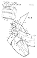
- Figs. 1 and 2 schematically show the whole of the air conditioning device which comprises a housing designated as a whole by 1.
- the housing 1 delimits a distribution chamber 2, forming an air intake duct 3, leading directly to the distribution chamber 2 and to a bypass opening 4 leading to at least one heat exchanger 5 held between the wall of the housing 1 and an internal partition 6.
- the heat exchanger 1 is most often constituted by a heating air heater but it can be constituted by two exchangers, one serving for the circulation of a hot fluid, for example the engine cooling liquid, the other to the circulation of a cold fluid, for example the refrigerant of a refrigeration circuit.
- the housing 1 is internally shaped to delimit a bearing surface 7 aligned with a part of the partition 6 to serve as a seat for a distributor flap 8 mounted on a shaft 9 which can be controlled from the exterior of the housing 1 by any suitable means known in the art of air conditioning devices.
- the housing 1 also delimits, by its partition 6 and its wall, seats 10, 11 against which parts of the distributor flap 8 can be applied simultaneously when it occupies the position illustrated in 8 a in broken lines.
- the air conditioning air which is forced into the pipe 3 cannot follow the path of the arrows f1 and f2, but only the path along the arrow f3, that is to say that this air is prevented from passing through the exchanger 5.
- the housing 1 is shaped to have an outlet 12 bordered by a seat 13 whose two opposite edges 13, 13 a are shown.
- the outlet 12 opens into a mixing chamber 14 homogenizing the temperature of the air and from which the housing 1 forms at least one pipe 15 leading to defrost and demister openings and at least one pipe 16 leading to other openings arranged, for example, substantially at the level of the vehicle floor.
- a front pipe 15 a can be provided to extend between the pipes 15.
- the lines 15 and 16 are arranged approximately 180 ° relative to each other.
- the mixing chamber 14 contains a valve 17 substantially shaped like a double-walled half-moon 20, 21.
- Fig. 8 shows that the valve 17 is supported by an axis 18 and a shaft 19 enabling it to be actuated from outside the housing 1.
- the valve has in its wall 20 a recess 22 causing it to delimit two arcs 23, 24.
- the arc 23 is cylindrical and concentric with the wall 1 a of the housing 1 in its part which joins the pipes 15 and 16 ( fig. 1).
- the cylindrical arc 23 has a radius adapted to that of the internal surface of the wall part 1 a .
- the arc 24 is cylindrical or of another shape and of smaller radius to provide a leakage passage with the seat part 13 as is explained in the following with reference to FIG. 6.
- the extreme edges 23 a , 24 a can be provided with flexible sealing lips to cooperate with the opposite edges 13, 13 a of the seat 13.
- Figs. 3 to 7 show different characteristic positions which can be occupied by the valve 17 in half-moon shape.
- valve 17 When it is desired to carry out an intense defrosting or demisting and only the pipe 15 needs to be supplied, the valve 17 is brought into the position illustrated in FIG. 3 for which the sealing lip 23 a , or the corresponding edge of the valve if there is no sealing lip, bears against the lateral side of the edge 13 a of the seat 13. In this way, the air arriving along arrow f2 or according to arrow f3 (fig. 2) is directed only towards the pipe or pipes 15 in the direction of arrow f4, since pipe 16 is completely closed. The air is also led to the front conduit 15 a but the latter is advantageously provided with a butterfly valve 26 the control of which can be synchronized with that of the valve 17 by a link 27 of any type known in the art.
- valve 17 When the demisting is considered sufficient, the valve 17 is brought into an intermediate position as shown in fig. 2 and 4, so that air having been heated or cooled or not, depending on the position occupied by the distributor flap 8, passes along the arrows f4 and f5, in the pipes 15 and 16 and possibly 15 a .
- the preferably cylindrical shape of the internal wall 21 of the valve 17 has the effect of reducing the pressure drop of the air circuit.
- the choice of the radius of the wall 21 is projections or lights 28 possibly provided ensures the intimate mixing of hot air and cold air in the mixing chamber 2 before it enters the conduits 15 , 16 and possibly 15 a .
- the mixing of the air is further improved, by the step 22 inside the valve 17 as well as by protrusions formed inside the valve when the latter has openings 28.
- valve 17 When it is desired that air is no longer vigorously blown towards the demister openings, the valve 17 is turned to be brought into the position illustrated in FIG. 5, that is to say the edge 24 a of the valve 17 is brought in line with the edge 13 of the seat.
- the sector 24 can be cylindrical or have a complex shape as illustrated diagrammatically in FIG. 6.
- the valve 17 can obviously occupy all the positions between those illustrated in FIG. 2 and in fig. 5 to direct a more or less significant flow of air towards the demister and heating or cooling vents located near the vehicle floor.
- Fig. 6 shows that by continuing to rotate the valve 17, the leakage space 25 is retained but that the outlet 12 of the air coming from the distribution chamber 2 is gradually blocked, which makes it possible to reduce the amount of air supplied to the so-called heating vents.
- valve 17 When it is desired to completely stop the supply of air to the vehicle, the valve 17 is pivoted as illustrated in FIG. 7, that is to say that the external part of the recess 22 bears against the external wall of the edge 13 of the seat, while the sealing lip 24 a of the sector 24 bears against the seat 13 a , which ensures complete closure of the outlet 12 and isolation of the distribution chamber 2 of the pipes 15, 16.
Abstract
Description
La présente invention concerne la climatisation des véhicules et plus particulièrement des véhicules terrestres.The present invention relates to the air conditioning of vehicles and more particularly of land vehicles.
La technique antérieure a fait connaître un grand nombre de dispositifs destinés à remplir la fonction ci-dessus.The prior art has made known a large number of devices intended to fulfill the above function.
La plupart des dispositifs comportent des conduites de sortie menant à des ouïes de dégivrage-désembuage, c'est-à-dire des ouïes ouvrant au voisinage du parebrise, et éventuellement des vitres latérales du véhicule et des conduites menant à des ouïes dites de chauffage qui débouchent près du plancher du véhicule.Most of the devices include outlet pipes leading to defrost-defog openings, that is to say openings opening in the vicinity of the windshield, and possibly side windows of the vehicle and pipes leading to so-called heating openings. which lead out near the floor of the vehicle.
La plupart des dispositifs connus existants comportant des volets permettant de fermer plus ou moins les conduites menant vers les ouïes de dégivrage-désembuage, d'une part, et vers les ouvertures de chauffage, d'autre part.Most of the existing known devices comprising shutters making it possible to more or less close the conduits leading to the deicing-defogging vents, on the one hand, and to the heating openings, on the other hand.
Lorsque de l'air extérieur ne doit pas du tout être amené à l'intérieur du véhicule, il est nécessaire de prévoir un troisième volet fermant l'alimentation d'air extérieur.When outside air is not to be brought inside the vehicle at all, it is necessary to provide a third shutter closing the outside air supply.
Le nombre de volets est encore augmenté, lorsqu'on décide d'utiliser un boîtier à volet mélangeur, c'est-à-dire dans lequel on réalise un mélange d'air chaud et d'air froid dans une chambre dite de mélange dans laquelle une plus ou moins grande quantité d'air ayant traversé un échangeur est amenée, puis brassée avec l'air froid.The number of flaps is further increased, when it is decided to use a mixer flap housing, that is to say in which a mixture of hot air and cold air is produced in a so-called mixing chamber in which a greater or lesser amount of air having passed through an exchanger is brought in, then stirred with cold air.
La présente invention crée un nouveau dispositif très simplifié dans lequel un seul volet permet d'assurer le mélange de veines d'air à des températures différentes et la distribution vers des oules de dégivrage-désembuage et des ouvertures de chauffage ou de refroidissement.The present invention creates a new very simplified device in which a single flap ensures the mixing of air streams at different temperatures and distribution to de-icing-demisting and heating or cooling openings.
Conformément à l'invention, le dispositif de climatisation pour véhicules du type dans lequel au moins un échangeur est disposé à l'intérieur d'un boîtier qui contient un volet pivotant pour le réglage de la température de l'air à l'intérieur d'une chambre de répartition, est caractérisé en ce que la chambre de répartition comporte une ouverture de sortie menant à une chambre de mélange communiquant avec au moins des conduites respectivement dirigées vers des ouïes de dégivrage-désembuage et vers des ouvertures de chauffage ou de refroidissement, la chambre de mélange contenant une vanne creuse en demi-lune coopérant avec les bords de sièges pour obturer totalement ou partiellement l'une ou l'autre des conduites ou l'ouverture de sortie de la chambre de répartition.According to the invention, the air conditioning device for vehicles of the type in which at least one exchanger is arranged inside a housing which contains a pivoting flap for adjusting the air temperature inside d '' a distribution chamber, is characterized in that the distribution chamber has an outlet opening leading to a mixing chamber communicating with at least pipes respectively directed to defrost-demister vents and to heating or cooling openings , the mixing chamber containing a hollow half-moon valve cooperating with the edges of the seats in order to completely or partially block either of the pipes or the outlet opening of the distribution chamber.
Diverses autres caractéristiques de l'invention ressortent d'aillures de la description détaillée qui suit.Various other characteristics of the invention will emerge from the details of the following detailed description.
Des formes de réalisation de l'objet de l'invention sont représentées, à titre d'exemples non limitatifs, aux dessins annexés.
- La fig. 1 est une perspective schématique partielle du dispositif de climatisation de l'invention.
- La fig. 2 est une coupe schématique du dispositif de climatisation pour véhicules, objet de l'invention, vue suivant la ligne II-II de la fig. 1.
- Les fig. 3 à 7 sont des coupes schématiques illustrant différentes positions caractéristiques de la vanne de commande du dispositif de la fig. 1.
- La fig. 8 est une perspective d'un mode de réalisation de la vanne des figures précédentes.
- Fig. 1 is a partial schematic perspective of the air conditioning device of the invention.
- Fig. 2 is a schematic section of the air conditioning device for vehicles, object of the invention, seen along line II-II of FIG. 1.
- Figs. 3 to 7 are schematic sections illustrating different characteristic positions of the control valve of the device of FIG. 1.
- Fig. 8 is a perspective of an embodiment of the valve of the preceding figures.
Les fig. 1 et 2 montrent de manière schématique l'ensemble du dispositif de climatisation qui comporte un boîtier désigné dans son ensemble par 1.Figs. 1 and 2 schematically show the whole of the air conditioning device which comprises a housing designated as a whole by 1.
Le boîtier 1 délimite une chambre de répartition 2, formant un conduit d'admission d'air 3, conduisant directement à la chambre de répartition 2 et à une ouverture de dérivation 4 menant à au moins un échangeur de chaleur 5 maintenu entre la paroi du boîtier 1 et une cloison interne 6.The housing 1 delimits a distribution chamber 2, forming an
L'échangeur de chaleur 1 est le plus souvent constitué par un aérotherme de chauffage mais il peut être constitué par deux échangeurs, l'un servant à la circulation d'un fluide chaud, par exemple le liquide de refroisissement du moteur, l'autre à la circulation d'un fluide froid, par exemple le fluide frigorigène d'un circuit frigorifique.The heat exchanger 1 is most often constituted by a heating air heater but it can be constituted by two exchangers, one serving for the circulation of a hot fluid, for example the engine cooling liquid, the other to the circulation of a cold fluid, for example the refrigerant of a refrigeration circuit.
Le boîtier 1 est conformé intérieurement pour délimiter une portée d'appui 7 alignée avec une partie de la cloison 6 pour servir de siège à un volet répartiteur 8 monté sur un arbre 9 pouvant être commandé depuis l'extérieur de boîtier 1 par tout moyen approprié connu dans la technique des dispositifs de climatisation.The housing 1 is internally shaped to delimit a bearing surface 7 aligned with a part of the partition 6 to serve as a seat for a distributor flap 8 mounted on a shaft 9 which can be controlled from the exterior of the housing 1 by any suitable means known in the art of air conditioning devices.
Le boîtier 1 délimite également, par sa cloison 6 et sa paroi des sièges 10, 11 contre lesquels peuvent être appliquées, simultanément, des parties du volet répartiteur 8 lorsqu'il occupe la position illustrée en 8 a en traits interrompus. Dans ce cas, l'air de climatisation qui est pulsé dans la conduite 3 ne peut pas suivre le trajet des flèches f₁ et f₂, mais seulement le trajet suivant la flèche f₃, c'est-à-dire que cet air est empêché de traverser l'échangeur 5.The housing 1 also delimits, by its partition 6 and its wall,
Lorsque le volet répartiteur 8 occupe l'autre position extrême qu'il peut prendre et qui est illustrée en 8 b, il prend appui sur la cloison 6 et contre le siège 10, de sorte que l'air pulsé par la conduite d'admission 3 ne peut pas suivre le trajet illustré par la flèche f₃, mais est obligé de suivre le trajet selon les flèches f₁ et f₂, c'est-à-dire qui l'air passe alors à travers l'échangeur 5.When the distributor flap 8 occupies the other extreme position which it can take and which is illustrated in 8b , it bears on the partition 6 and against the
Pour toutes les positions de volet répartiteur 8 intermédiaires aux deux positions décrites ci-dessus, des fractions plus ou moins importantes de l'air pulsé à travers la conduite d'admission 3 suivent le trajet des flèches f₁ et f₂, d'une part, et f₃, d'autre part, de sorte que l'air est ainsi plus ou moins chauffé ou refroidi selon que l'échangeur 5 est uniquement un échangeur de chauffage ou qu'il comporte aussi un échangeur refroidisseur.For all the distributor flap positions 8 intermediate to the two positions described above, more or less large fractions of the air blown through the
Le boîtier 1 est conformé pour présenter une sortie 12 bordée par un siège 13 dont les deux bords opposés 13, 13 a sont représentés. La sortie 12 débouche dans une chambre de mélange 14 homogénéisant la température de l'air et à partir de laquelle le boîtier 1 forme au moins une conduite 15 menant vers des ouïes de dégivrage et désembuage et au moins une conduite 16 menant vers d'autres ouïes disposées, par exemple, sensiblement au niveau du plancher du véhicule. Un conduit frontal 15 a peut être prévu pour s'étendre entre les conduites 15.The housing 1 is shaped to have an
Comme le montre le dessin, les conduites 15 et 16 sont disposées approximativement à 180° l'une par rapport à l'autre.As shown in the drawing, the
La chambre de mélange 14 contient une vanne 17 conformée sensiblement à la maniére d'une demi-lune à double parois 20, 21.The
La fig. 8 montre que la vanne 17 est supportée par un axe 18 et un arbre 19 permettant de l'actionner depuis l'extérieur du boîtier 1.Fig. 8 shows that the
Comme l'illustre la fig. 8, la vanne présente dans sa paroi 20 un décrochement 22 faisant qu'elle délimite deux arcs 23, 24. L'arc 23 est cylindrique et concentrique à la paroi 1 a du boîtier 1 dans sa partie qui joint les conduites 15 et 16 (fig. 1). L'arc cylindrique 23 est de rayon adapté à celui de la surface interne de la partie de paroi 1 a. L'arc 24 est cylindrique ou d'une autre forme et de plus petit rayon pour ménager un passage de fuite avec la partie de siège 13 comme cela est expliqué dans ce qui suit en se référant à la fig. 6.As illustrated in fig. 8, the valve has in its wall 20 a
Les bords extrêmes 23 a, 24 a peuvent être munis de lèvres souples d'étanchéité pour coopérer avec les bords opposés 13, 13 a du siège 13.The
Les fig. 3 à 7 montrent différentes positions caractéristiques pouvant être occupées par la vanne 17 en demi-lune.Figs. 3 to 7 show different characteristic positions which can be occupied by the
Lorsqu'il est souhaité de procéder à un dégivrage ou désembuage intense et que seule la conduite 15 doit être alimentée, la vanne 17 est amenée dans la position illustrée à la fig . 3 pour laquelle le lèvre d'étanchéité 23 a, ou le bord correspondant de la vanne s'il n'existe pas de lèvre d'étanchéité, vient en appui contre le côté latéral du bord 13 a du siège 13. De cette manière, l'air arrivant suivant la flèche f₂ ou suivant la flèche f₃ (fig. 2) est dirigé uniquement vers la ou les conduites 15 dans le sens de la flèche f₄, puisque la conduite 16 est complètement obturée. L'air est également mené vers le conduit frontal 15 a mais celui-ci est avantageusement muni d'un papillon 26 dont la commande peut être synchronisée à celle de la vanne 17 par une liaison 27 d'un type quelconque connu dans la technique.When it is desired to carry out an intense defrosting or demisting and only the
Lorsque le désembuage est estimé suffisant, la vanne 17 est amenée dans une position intermédiaire telle que représentée aud fig. 2 et 4, de sorte que de l'air ayant ou non été chauffé ou refroidi, suivant la position occupée par le volet répartiteur 8, passe suivant les flèches f₄ et f₅, dans les conduites 15 et 16 et éventuellement 15 a.When the demisting is considered sufficient, the
La forme de préférence cylindrique de la paroi interne 21 de la vanne 17 a pour effet de réduire la perte de charge du circuit d'air. En outre, le choix du rayon de la paroi 21 est des saillies ou lumières 28 éventuellement prévues assure le mélange intime de l'air chaud et de l'air froid dans la chambre de mélange 2 avant que celui-ci pénètre dans les conduites 15, 16 et éventuellement 15 a.The preferably cylindrical shape of the
Le brassage de l'air est encore amélioré, par le décrochement 22 à l'intérieur de la vanne 17 ainsi que par des protubérances formées à l'intérieur de la vanne lorsque celle-ci présente des lumières 28.The mixing of the air is further improved, by the
Lorsqu'il est souhaité que de l'air ne soit plus soufflé vigoureusement vers les ouïes de désembuage, la vanne 17 est tournée pour être amenée dans la position illustrée par la fig. 5, c'est-à-dire que le bord 24 a de la vanne 17 est amené à l'aplomb du bord 13 du siège.When it is desired that air is no longer vigorously blown towards the demister openings, the
Etant donné que le rayon du secteur 24 est plus petit que la distance d séparant l'axe géométrique des axe et arbre 18, 19 de la partie du siège 13, un espace 25 est maintenu libre, ce qui consitue une fuite pouvant être calibrée pour le passage d'air devant être dirigé notamment vers le pare-brise du véhicule pour empêcher qu'il soit à nouveau embué. Le secteur 24 peut être cylindrique ou présenter une forme complexe comme illustré schématiquement à la fig. 6.Since the radius of the
La vanne 17 peut occuper évidemment toutes les positions comprises entre celles illustrées à la fig. 2 et à la fig. 5 pour diriger un flux d'air plus ou moins important vers les ouïes de désembuage et celles de chauffage ou refroidissement situées à proximité du plancher du véhicule.The
La fig. 6 montre qu'en continuant à faire tourner la vanne 17, l'espace de fuite 25 est conservé mais que la sortie 12 de l'air venant de la chambre de répartition 2 est progressivement obturée, ce qui permet de réduire la quantité d'air amenée vers les ouïes dites de chauffage.Fig. 6 shows that by continuing to rotate the
Lorsqu'il est souhaité d'interrompre complètement l'amenée d'air dans le véhicule, la vanne 17 est pivotée comme l'illustre la fig. 7, c'est-à-dire que la partie externe du décrochement 22 prend appui contre la paroi extérieure du bord 13 du siège, tandis que la lèvre d'étanchéité 24 a du secteur 24 prend appui contre le siège 13 a, ce qui assure la fermeture complète de la sortie 12 et l'isolement de la chambre de répartition 2 des conduites 15, 16.When it is desired to completely stop the supply of air to the vehicle, the
Dans ce qui précède, il a été considéré que le volet mélangeur 8 et la vanne en demi-lune 17 étaient commandés manuellement. On ne sortirait pas du cadre de l'invention en reliant les arbres de commande du volet mélangeur 8, de la vanne 17 et du papillon 26 par des moyens assurant leur synchronisation ou encore par des moyens asservis à un dispositif de mesure de température régnant dans l'habitacle du véhicule ou à l'extérieur de celui-ci.In the above, it was considered that the mixer flap 8 and the half-
L'invention n'est pas limitée aux exemples de réalisation représentés et décrits en détail car diverses modifications peuvent y être apportées sans sortir de son cadre. The invention is not limited to the embodiments shown and described in detail since various modifications can be made thereto without departing from its scope.
Claims (12)
Applications Claiming Priority (2)
| Application Number | Priority Date | Filing Date | Title |
|---|---|---|---|
| FR8613156A FR2604127B1 (en) | 1986-09-19 | 1986-09-19 | AIR CONDITIONING DEVICE WITH MIXER SHUTTER FOR VEHICLES AND SIMILAR APPLICATIONS |
| FR8613156 | 1986-09-19 |
Publications (2)
| Publication Number | Publication Date |
|---|---|
| EP0266230A1 true EP0266230A1 (en) | 1988-05-04 |
| EP0266230B1 EP0266230B1 (en) | 1991-01-02 |
Family
ID=9339121
Family Applications (1)
| Application Number | Title | Priority Date | Filing Date |
|---|---|---|---|
| EP19870402013 Expired - Lifetime EP0266230B1 (en) | 1986-09-19 | 1987-09-09 | Air conditioning device including an air mixing valve for vehicles and similar applications |
Country Status (4)
| Country | Link |
|---|---|
| EP (1) | EP0266230B1 (en) |
| DE (1) | DE3766936D1 (en) |
| ES (1) | ES2019958B3 (en) |
| FR (1) | FR2604127B1 (en) |
Cited By (7)
| Publication number | Priority date | Publication date | Assignee | Title |
|---|---|---|---|---|
| DE19518280A1 (en) * | 1994-06-01 | 1995-12-07 | Valeo Thermique Habitacle | Heating and ventilation device for passenger space of vehicle |
| EP0858919A2 (en) | 1997-02-17 | 1998-08-19 | AURORA Konrad G. Schulz GmbH & Co | Air passage switching device |
| FR2778148A1 (en) * | 1998-04-29 | 1999-11-05 | Valeo Climatisation | DEVICE FOR HEATING-VENTILATION OF THE INTERIOR OF A MOTOR VEHICLE |
| FR2797810A1 (en) * | 1999-08-30 | 2001-03-02 | Valeo Climatisation | Calibration of air inlet sections of vehicle air conditioning installation comprises air inlet box whose air inlet passage is adjusted by flap, box walls having angular segments accounting for flap drive mechanism tolerances |
| FR2845946A1 (en) * | 2002-10-18 | 2004-04-23 | Valeo Climatisation | Motor vehicle heating, ventilation/air conditioning system has regulator made from two halves with gap between inner and outer walls |
| EP1510378A2 (en) * | 2003-08-25 | 2005-03-02 | Behr GmbH & Co. KG | Drum valve |
| US20160059671A1 (en) * | 2014-08-27 | 2016-03-03 | Delphi Technologies, Inc. | Heating ventilation and air-conditioning (hvac) module with a curved valve |
Families Citing this family (9)
| Publication number | Priority date | Publication date | Assignee | Title |
|---|---|---|---|---|
| DE3821541C2 (en) * | 1988-06-25 | 1997-05-07 | Behr Gmbh & Co | Device for ventilating and / or heating the interior of motor vehicles |
| GB2263530B (en) * | 1992-01-17 | 1995-09-13 | Valeo Climate Control Ltd | Air distribution unit |
| JP3774961B2 (en) * | 1996-11-15 | 2006-05-17 | 株式会社デンソー | Air conditioner for vehicles |
| ES2145663B1 (en) * | 1996-12-11 | 2001-02-01 | Valeo Climatizacion Sa | DEVICE FOR HEATING / VENTILATION OF THE ROOM AND FOR COOLING THE MOTOR OF A MOTOR VEHICLE. |
| FR2796335B1 (en) † | 1999-07-12 | 2001-10-05 | Valeo Climatisation | HEATING SYSTEM, ESPECIALLY A TYPE OF AIR CONDITIONING HAVING A MIXING SHUTTER |
| DE10031991B4 (en) * | 2000-06-30 | 2004-02-05 | Valeo Klimasysteme Gmbh | damper |
| DE10152221B4 (en) † | 2001-10-23 | 2013-08-14 | Behr France S.A.R.L. | Heating or air conditioning for a vehicle |
| FR2859134B1 (en) * | 2003-08-29 | 2007-09-28 | Valeo Climatisation | AIR DISTRIBUTION MODULE FOR A VENTILATION, HEATING AND / OR AIR CONDITIONING FACILITY |
| DE102017111075B4 (en) | 2017-05-22 | 2018-12-27 | Miele & Cie. Kg | A sealing device and method for the leak-proof sealing of a radiator with a bottom plate for a microwave combined steam cooker, and method of making the sealing device, apparatus and computer program product for carrying out the methods, and steam ovens with microwave function |
Citations (7)
| Publication number | Priority date | Publication date | Assignee | Title |
|---|---|---|---|---|
| FR2247680A1 (en) * | 1973-10-12 | 1975-05-09 | Delanair Ltd | |
| GB2102560A (en) * | 1981-07-28 | 1983-02-02 | Valeo | Flap for controlling the flow air through a duct in particular in a heater or air conditioner installation for a motor vehicle |
| DE3226438A1 (en) * | 1982-07-15 | 1984-01-19 | Bayerische Motoren Werke AG, 8000 München | Device for the optional connecting of two spaces by an air duct |
| GB2130359A (en) * | 1982-11-15 | 1984-05-31 | Ford Motor Co | Heating and ventilation system for vehicles |
| FR2562845A1 (en) * | 1984-04-13 | 1985-10-18 | Chausson Usines Sa | Air conditioning device for vehicles |
| GB2168786A (en) * | 1984-12-20 | 1986-06-25 | Austin Rover Group | An air distribution valve for an air heater |
| DE8632160U1 (en) * | 1985-12-03 | 1987-01-29 | Elbi International S.P.A., Collegno, Turin/Torino, It |
-
1986
- 1986-09-19 FR FR8613156A patent/FR2604127B1/en not_active Expired - Lifetime
-
1987
- 1987-09-09 DE DE8787402013T patent/DE3766936D1/en not_active Expired - Lifetime
- 1987-09-09 EP EP19870402013 patent/EP0266230B1/en not_active Expired - Lifetime
- 1987-09-09 ES ES87402013T patent/ES2019958B3/en not_active Expired - Lifetime
Patent Citations (7)
| Publication number | Priority date | Publication date | Assignee | Title |
|---|---|---|---|---|
| FR2247680A1 (en) * | 1973-10-12 | 1975-05-09 | Delanair Ltd | |
| GB2102560A (en) * | 1981-07-28 | 1983-02-02 | Valeo | Flap for controlling the flow air through a duct in particular in a heater or air conditioner installation for a motor vehicle |
| DE3226438A1 (en) * | 1982-07-15 | 1984-01-19 | Bayerische Motoren Werke AG, 8000 München | Device for the optional connecting of two spaces by an air duct |
| GB2130359A (en) * | 1982-11-15 | 1984-05-31 | Ford Motor Co | Heating and ventilation system for vehicles |
| FR2562845A1 (en) * | 1984-04-13 | 1985-10-18 | Chausson Usines Sa | Air conditioning device for vehicles |
| GB2168786A (en) * | 1984-12-20 | 1986-06-25 | Austin Rover Group | An air distribution valve for an air heater |
| DE8632160U1 (en) * | 1985-12-03 | 1987-01-29 | Elbi International S.P.A., Collegno, Turin/Torino, It |
Cited By (10)
| Publication number | Priority date | Publication date | Assignee | Title |
|---|---|---|---|---|
| DE19518280A1 (en) * | 1994-06-01 | 1995-12-07 | Valeo Thermique Habitacle | Heating and ventilation device for passenger space of vehicle |
| FR2720693A1 (en) * | 1994-06-01 | 1995-12-08 | Valeo Thermique Habitacle | Device for heating and / or ventilating the passenger compartment of a vehicle. |
| DE19518280B4 (en) * | 1994-06-01 | 2004-09-02 | Valeo Climatisation S.A. | Device for heating and / or ventilation of the passenger compartment of a vehicle |
| EP0858919A2 (en) | 1997-02-17 | 1998-08-19 | AURORA Konrad G. Schulz GmbH & Co | Air passage switching device |
| FR2778148A1 (en) * | 1998-04-29 | 1999-11-05 | Valeo Climatisation | DEVICE FOR HEATING-VENTILATION OF THE INTERIOR OF A MOTOR VEHICLE |
| FR2797810A1 (en) * | 1999-08-30 | 2001-03-02 | Valeo Climatisation | Calibration of air inlet sections of vehicle air conditioning installation comprises air inlet box whose air inlet passage is adjusted by flap, box walls having angular segments accounting for flap drive mechanism tolerances |
| FR2845946A1 (en) * | 2002-10-18 | 2004-04-23 | Valeo Climatisation | Motor vehicle heating, ventilation/air conditioning system has regulator made from two halves with gap between inner and outer walls |
| EP1510378A2 (en) * | 2003-08-25 | 2005-03-02 | Behr GmbH & Co. KG | Drum valve |
| EP1510378A3 (en) * | 2003-08-25 | 2005-11-16 | Behr GmbH & Co. KG | Drum valve |
| US20160059671A1 (en) * | 2014-08-27 | 2016-03-03 | Delphi Technologies, Inc. | Heating ventilation and air-conditioning (hvac) module with a curved valve |
Also Published As
| Publication number | Publication date |
|---|---|
| ES2019958B3 (en) | 1991-07-16 |
| FR2604127A1 (en) | 1988-03-25 |
| DE3766936D1 (en) | 1991-02-07 |
| FR2604127B1 (en) | 1990-12-14 |
| EP0266230B1 (en) | 1991-01-02 |
Similar Documents
| Publication | Publication Date | Title |
|---|---|---|
| EP1013491B1 (en) | Vehicle heating and/or air conditioning with improved air mixing | |
| EP0266230B1 (en) | Air conditioning device including an air mixing valve for vehicles and similar applications | |
| FR2659603A1 (en) | DEVICE FOR HEATING AND VENTILATING THE INTERIOR OF A MOTOR VEHICLE. | |
| EP2889168B1 (en) | Heating, ventilation and/or air conditioning device | |
| EP1514707B1 (en) | Improved air temperature control of a passenger cell heating and/or air conditioning device | |
| EP3683075A1 (en) | Heating, ventilation and/or air conditioning device | |
| EP0709241B1 (en) | Device for heating and/or ventilating a vehicle interior | |
| FR2715352A1 (en) | Heating and ventilation device for the passenger compartment of a motor vehicle. | |
| WO2020174146A1 (en) | Heating and/or ventilation and/or air conditioning system comprising a mixing flap with deflector | |
| FR2562845A1 (en) | Air conditioning device for vehicles | |
| FR2778148A1 (en) | DEVICE FOR HEATING-VENTILATION OF THE INTERIOR OF A MOTOR VEHICLE | |
| FR2713154A1 (en) | Dispensing device for a motor vehicle air conditioning installation. | |
| FR2761011A1 (en) | Adjustment device for air flow control in vehicle climate control system | |
| FR2719809A1 (en) | Heating and ventilation device for the passenger compartment of a vehicle. | |
| FR2773111A1 (en) | Ventilation and heating assembly for motor vehicle | |
| EP1514708B1 (en) | Heating and/or air conditioning device for vehicle compartment, with sophisticated aerothermic management | |
| FR2794070A1 (en) | Air mixing device for automobile air conditioning comprises flaps, pivoting on support moved by lever, distributing cold air between cold air and reheated air branches | |
| FR2746714A1 (en) | Control of heating and cooling of interior of motor vehicle | |
| EP0600779A1 (en) | Device for heating, ventilating and/or air conditioning the interior of a motor vehicle | |
| FR2710878A1 (en) | Device for the heating and ventilation of the passenger compartment (cockpit) of a motor vehicle | |
| FR2778151A1 (en) | Air distributor for vehicle interior heater/air conditioning | |
| FR2786134A1 (en) | Heating and ventilating assembly for vehicle passenger compartment comprises upper and lower branches with outlets sized to feed only heated air to lateral section of mixing zone. | |
| EP3268239B1 (en) | Air-conditioning circuits for a motor vehicle | |
| EP0749857A1 (en) | Device for heating and ventilating the interior of a vehicle | |
| EP2240338B1 (en) | Single shutter for closing the central and lateral air outlets in a motor vehicle cabin air-conditioning system. |
Legal Events
| Date | Code | Title | Description |
|---|---|---|---|
| PUAI | Public reference made under article 153(3) epc to a published international application that has entered the european phase |
Free format text: ORIGINAL CODE: 0009012 |
|
| 17P | Request for examination filed |
Effective date: 19870914 |
|
| AK | Designated contracting states |
Kind code of ref document: A1 Designated state(s): DE ES IT |
|
| 17Q | First examination report despatched |
Effective date: 19891006 |
|
| RAP1 | Party data changed (applicant data changed or rights of an application transferred) |
Owner name: VALEO THERMIQUE MOTEUR |
|
| GRAA | (expected) grant |
Free format text: ORIGINAL CODE: 0009210 |
|
| AK | Designated contracting states |
Kind code of ref document: B1 Designated state(s): DE ES IT |
|
| REF | Corresponds to: |
Ref document number: 3766936 Country of ref document: DE Date of ref document: 19910207 |
|
| ITF | It: translation for a ep patent filed |
Owner name: SOCIETA' ITALIANA BREVETTI S.P.A. |
|
| PLBE | No opposition filed within time limit |
Free format text: ORIGINAL CODE: 0009261 |
|
| STAA | Information on the status of an ep patent application or granted ep patent |
Free format text: STATUS: NO OPPOSITION FILED WITHIN TIME LIMIT |
|
| 26N | No opposition filed | ||
| PGFP | Annual fee paid to national office [announced via postgrant information from national office to epo] |
Ref country code: ES Payment date: 19930930 Year of fee payment: 7 |
|
| PG25 | Lapsed in a contracting state [announced via postgrant information from national office to epo] |
Ref country code: ES Free format text: LAPSE BECAUSE OF THE APPLICANT RENOUNCES Effective date: 19940910 |
|
| REG | Reference to a national code |
Ref country code: ES Ref legal event code: FD2A Effective date: 19991007 |
|
| PG25 | Lapsed in a contracting state [announced via postgrant information from national office to epo] |
Ref country code: IT Free format text: LAPSE BECAUSE OF NON-PAYMENT OF DUE FEES Effective date: 20050909 |
|
| PGFP | Annual fee paid to national office [announced via postgrant information from national office to epo] |
Ref country code: DE Payment date: 20060907 Year of fee payment: 20 |