EP0265486B1 - Systeme et ensemble de cryostat modulaire a detecteur de photons - Google Patents
Systeme et ensemble de cryostat modulaire a detecteur de photons Download PDFInfo
- Publication number
- EP0265486B1 EP0265486B1 EP19870902944 EP87902944A EP0265486B1 EP 0265486 B1 EP0265486 B1 EP 0265486B1 EP 19870902944 EP19870902944 EP 19870902944 EP 87902944 A EP87902944 A EP 87902944A EP 0265486 B1 EP0265486 B1 EP 0265486B1
- Authority
- EP
- European Patent Office
- Prior art keywords
- chamber
- detector
- base
- vacuum
- probe
- Prior art date
- Legal status (The legal status is an assumption and is not a legal conclusion. Google has not performed a legal analysis and makes no representation as to the accuracy of the status listed.)
- Expired - Lifetime
Links
- 230000007704 transition Effects 0.000 claims abstract description 16
- 239000012530 fluid Substances 0.000 claims abstract description 6
- 238000001816 cooling Methods 0.000 claims description 26
- 239000000523 sample Substances 0.000 claims description 16
- 230000008878 coupling Effects 0.000 claims description 3
- 238000010168 coupling process Methods 0.000 claims description 3
- 238000005859 coupling reaction Methods 0.000 claims description 3
- 230000006835 compression Effects 0.000 claims 1
- 238000007906 compression Methods 0.000 claims 1
- 230000005855 radiation Effects 0.000 abstract description 4
- 229910052732 germanium Inorganic materials 0.000 description 7
- GNPVGFCGXDBREM-UHFFFAOYSA-N germanium atom Chemical compound [Ge] GNPVGFCGXDBREM-UHFFFAOYSA-N 0.000 description 7
- IJGRMHOSHXDMSA-UHFFFAOYSA-N Atomic nitrogen Chemical compound N#N IJGRMHOSHXDMSA-UHFFFAOYSA-N 0.000 description 4
- 238000004891 communication Methods 0.000 description 3
- 239000007788 liquid Substances 0.000 description 3
- 238000005259 measurement Methods 0.000 description 3
- RYGMFSIKBFXOCR-UHFFFAOYSA-N Copper Chemical compound [Cu] RYGMFSIKBFXOCR-UHFFFAOYSA-N 0.000 description 2
- 239000004593 Epoxy Substances 0.000 description 2
- 229910001374 Invar Inorganic materials 0.000 description 2
- RTAQQCXQSZGOHL-UHFFFAOYSA-N Titanium Chemical compound [Ti] RTAQQCXQSZGOHL-UHFFFAOYSA-N 0.000 description 2
- 229910052782 aluminium Inorganic materials 0.000 description 2
- XAGFODPZIPBFFR-UHFFFAOYSA-N aluminium Chemical compound [Al] XAGFODPZIPBFFR-UHFFFAOYSA-N 0.000 description 2
- 230000000712 assembly Effects 0.000 description 2
- 238000000429 assembly Methods 0.000 description 2
- 230000008859 change Effects 0.000 description 2
- 239000003610 charcoal Substances 0.000 description 2
- 239000002800 charge carrier Substances 0.000 description 2
- 239000000110 cooling liquid Substances 0.000 description 2
- 229910052802 copper Inorganic materials 0.000 description 2
- 239000010949 copper Substances 0.000 description 2
- 230000003993 interaction Effects 0.000 description 2
- 230000013011 mating Effects 0.000 description 2
- 229910052757 nitrogen Inorganic materials 0.000 description 2
- 239000004065 semiconductor Substances 0.000 description 2
- 229910001220 stainless steel Inorganic materials 0.000 description 2
- 239000010935 stainless steel Substances 0.000 description 2
- 239000010936 titanium Substances 0.000 description 2
- 229910052719 titanium Inorganic materials 0.000 description 2
- 229910001200 Ferrotitanium Inorganic materials 0.000 description 1
- FYYHWMGAXLPEAU-UHFFFAOYSA-N Magnesium Chemical compound [Mg] FYYHWMGAXLPEAU-UHFFFAOYSA-N 0.000 description 1
- 238000010521 absorption reaction Methods 0.000 description 1
- AZDRQVAHHNSJOQ-UHFFFAOYSA-N alumane Chemical group [AlH3] AZDRQVAHHNSJOQ-UHFFFAOYSA-N 0.000 description 1
- 230000008901 benefit Effects 0.000 description 1
- 238000012512 characterization method Methods 0.000 description 1
- 238000010276 construction Methods 0.000 description 1
- 230000008602 contraction Effects 0.000 description 1
- 239000012809 cooling fluid Substances 0.000 description 1
- 239000013078 crystal Substances 0.000 description 1
- 238000013461 design Methods 0.000 description 1
- 238000001514 detection method Methods 0.000 description 1
- 230000005684 electric field Effects 0.000 description 1
- 238000011156 evaluation Methods 0.000 description 1
- 239000011152 fibreglass Substances 0.000 description 1
- 230000005669 field effect Effects 0.000 description 1
- 235000013305 food Nutrition 0.000 description 1
- 230000005251 gamma ray Effects 0.000 description 1
- 239000011521 glass Substances 0.000 description 1
- 229910052749 magnesium Inorganic materials 0.000 description 1
- 239000011777 magnesium Substances 0.000 description 1
- 238000004519 manufacturing process Methods 0.000 description 1
- 229910052751 metal Inorganic materials 0.000 description 1
- 239000002184 metal Substances 0.000 description 1
- 150000002739 metals Chemical class 0.000 description 1
- 238000012544 monitoring process Methods 0.000 description 1
- 238000005086 pumping Methods 0.000 description 1
- 238000007789 sealing Methods 0.000 description 1
- 230000004304 visual acuity Effects 0.000 description 1
Images


Classifications
-
- F—MECHANICAL ENGINEERING; LIGHTING; HEATING; WEAPONS; BLASTING
- F25—REFRIGERATION OR COOLING; COMBINED HEATING AND REFRIGERATION SYSTEMS; HEAT PUMP SYSTEMS; MANUFACTURE OR STORAGE OF ICE; LIQUEFACTION SOLIDIFICATION OF GASES
- F25D—REFRIGERATORS; COLD ROOMS; ICE-BOXES; COOLING OR FREEZING APPARATUS NOT OTHERWISE PROVIDED FOR
- F25D19/00—Arrangement or mounting of refrigeration units with respect to devices or objects to be refrigerated, e.g. infrared detectors
- F25D19/006—Thermal coupling structure or interface
-
- F—MECHANICAL ENGINEERING; LIGHTING; HEATING; WEAPONS; BLASTING
- F17—STORING OR DISTRIBUTING GASES OR LIQUIDS
- F17C—VESSELS FOR CONTAINING OR STORING COMPRESSED, LIQUEFIED OR SOLIDIFIED GASES; FIXED-CAPACITY GAS-HOLDERS; FILLING VESSELS WITH, OR DISCHARGING FROM VESSELS, COMPRESSED, LIQUEFIED, OR SOLIDIFIED GASES
- F17C3/00—Vessels not under pressure
- F17C3/02—Vessels not under pressure with provision for thermal insulation
- F17C3/08—Vessels not under pressure with provision for thermal insulation by vacuum spaces, e.g. Dewar flask
- F17C3/085—Cryostats
-
- G—PHYSICS
- G01—MEASURING; TESTING
- G01T—MEASUREMENT OF NUCLEAR OR X-RADIATION
- G01T7/00—Details of radiation-measuring instruments
-
- F—MECHANICAL ENGINEERING; LIGHTING; HEATING; WEAPONS; BLASTING
- F17—STORING OR DISTRIBUTING GASES OR LIQUIDS
- F17C—VESSELS FOR CONTAINING OR STORING COMPRESSED, LIQUEFIED OR SOLIDIFIED GASES; FIXED-CAPACITY GAS-HOLDERS; FILLING VESSELS WITH, OR DISCHARGING FROM VESSELS, COMPRESSED, LIQUEFIED, OR SOLIDIFIED GASES
- F17C2221/00—Handled fluid, in particular type of fluid
- F17C2221/01—Pure fluids
- F17C2221/014—Nitrogen
Definitions
- This invention relates to cryogenically cooled radiation detectors and more specifically to means in a cryostat for thermally and mechanically connecting a detector to a dewar.
- Photon detectors or spectrometers are useful in measuring low low levels of radionuclides. Examples of such measurements include monitoring of the environment and effluent discharge of nuclear power stations, measurement of food product for human intake and evaluation of the natural environment. Because of the radionuclide content of some samples, it has become standard practice to use the resolving power of germanium semiconductor detectors to identify and quantify the isotopes present. Germanium semiconductor gamma-ray spectrometers have been developed to provide optimum performance for such measurement. When x- or gamma rays impinge on a germanium detector, there is a finite probability of an interaction occurring which results in the creation of electron-hole pairs.
- I o the beam intensity at the surface of the detector and X is the distance from the surface
- 1/ ⁇ is the absorption coefficient and can be considered as the sum of three components due respectively to the photoelectric, Compton and pair-production processes.
- the germanium detector must be vacuum-jacketed and cryogenically cool. Normally, such detectors are cooled to below 100°K. A nominal operating temperature is 77°K.
- the germanium detector is incorporated in a cryostat.
- the cryostat comprises an evacuated housing surrounding the detector, the detector itself, a cryogenically cooled field effect transitor preamplifier in the housing, electronics circuit boards exterior to the housing mounted on support means coaxial with and extending from the detector, and means for communicating the detector with a cryogenic cooling source such as liquid nitrogen.
- Cryostats are provided in various sizes and configurations for various applications.
- different dewars are utilized for varying applications.
- One form of cryostat may be connected to a dewar having a handle projecting therefrom which is balanced for maintaining the cryostat in a hand-held horizontal disposition.
- Different dewars may be provided to provide for eight hour or twenty-four hour holding time.
- dewars may be provided which have cryostats projecting from a top portion, a bottom portion or a side thereof.
- nominal dewars may come in sizes of .4, 1.2, 7.5, 15, 25 or 30 liters.
- Different specific applications require different combinations of dewar and cryostat.
- the conventional means for connecting cooling devices to the detector has resulted in construction of a closure in which vacuum-jacket surrounding the detector is the same vacuum jacket that must surround the portion of the cryostat extending from the detector into the dewar and in some cases the dewar vacuum jacket.
- This widely successfully used and conventional design does not permit modularity of assembly between detector heads and different cryostats or different dewars.
- the experience in the art is that in reworking of detectors to move them from one cryostat assembly to another, yield rate is low. Consequently, an expensive inventory of cryostats must be maintained for a number of applications.
- US-A-3,483,709 discloses a photon detector system comprising two relatively detachable portions, the first portion comprising a vacuum flask having a chamber for holding cryogenic fluid and a vacuum jacket around the chamber, the second portion comprising a detector and a vacuum jacket around the detector, and first and second transition probes for thermally coupling the portions, each probe having a tube, the tube of one probe being constructed and arranged to encircle the tube of the other probe to form an annular chamber therewith, the tubes each having an associated base from which it extends, the base of the one probe connecting the vacuum jacket of the flask to the annular chamber and means mounting the second portion to close the annular chamber, and the base of the other probe being firmly connected to the chamber, a thermally conducting member in the tube of the other probe and thermally connected to the base, a thermal junction connecting said member to a member thermally connected to the detector.
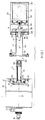
- Figures 1 through 3 are each elevation views partially in cross section, each illustrating the same components, the same reference numerals being used for the same components in each Figure.
- FIGs 1 and 2 differing forms of sub-assembly are illustrated, and in Figure 3, the system is shown in an assembled form ready for operation for radiation detection.
- the system comprises a dewar 1 and cryostat assembly or cryostat 2.
- the portions of the system utilized for thermally and mechanically connecting the detector to the dewar may be viewed as part of the cryostat assembly 2 rather than the dewar 1, although such characterization is not critical in understanding operation of the present invention.
- the dewar 1 comprises a canister 10 enclosing a central chamber 11 for holding cryogenic liquid enclosed by a wall 13, preferably liquid nitrogen.
- a concentric vacuum jacket 12 surrounds the chamber 11 and is disposed between the wall 13 and a dewar outer wall 14 having an opening 15.
- Ports 16 and 17 are provided each respectively communicating with the chamber 11 and vacuum-jacket 12 in a prior art manner for respectively providing cooling liquid and for coupling to a vacuum pump.
- a detector head assembly 20 includes a conventional detector 21 comprising a germanium crystal in an enclosure 22.
- the detector 21 and enclosure 22 are mounted to a platform 24 supported to support means 26 affixed to a base 28 having an external circular recess 29 and closing a detector head housing 30.
- the entire detector head housing 30 is evacuated.
- Thermal conduction means 35 extend from outside the detector head housing 30 through the base 28 to make thermal contact with the platform 24 and germanium detector 21.
- the thermal conduction means 35 comprises a copper rod mounted along an axis 37 common to the detector 21, housing 30 and enclosure 22.
- a bellows 36 seals around the conduction member 35 adjacent one end thereof outside the detector head assembly and sealably engages the base 28 opening into the interior of the housing 30.
- the transition means 40 provides for the transition from the dewar 1 to detector head 20 and provide releasable mechanical and thermal connection therebetween and comprises a cooling rod assembly 41 and cooling rod housing assembly 52.
- the cooling rod assembly 41 includes a base portion 42 for mounting to the wall 13 of the cooling fluid chamber 11 and in thermal communication therewith by mounting means such as screws 43.
- a cooling rod 45 projects axially out of the dewar 1 and includes a radially central and an axial end thereof receptacle 44 for mating with and receiving an end of the conduction rod 35.
- the receptacle 44 is mounted at an end of the cooling rod 43 in a manner to allow for relative thermal expansion and contraction as further described below.
- the cooling rod 45 may be constructed of a plurality of metals.
- a cooling rod housing assembly 52 comprises a base 53 for mounting to the outer wall 14 of the dewar 11 facing the cryostat 2 and covering the opening 15.
- a cylindrical housing member 54 Extending axially from the base 53 is a cylindrical housing member 54 for mounting coaxially with the arm 45 and the conduction member 35 and defining a chamber 55 therearound.
- An extremity of the member 54 remote from the base 53 is dimensioned to be received in the recess 29 and sealed by sealing means 56 in the base 28 of the detector assembly housing 30 so that a vacuum may be maintained.
- the chambers 55 and 12 are in fluid communication and define a common sealed chamber.
- Electronics circuit boards 58 carrying prior art circuitry and electrically connected to the detector 21 in a prior art manner may be mounted on the radially exterior surface of the member 54.
- a port 59 may be provided through the base portion 52 to evacuate the volume in which the circuits 58 are placed.
- a shroud 60 may be mounted concentrically over the detector head assembly 30 and seal the volume between the base 28 of the detector head assembly 20 and the base 53 of the cooling rod housing assembly 52 means so that the entire assembly as illustrated in Figures 1 though 3 is sealed.
- the receptacle 44 preferably is made out of titanium steel.
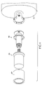
- Figure 4 is an exploded axonometric view further illustrating in one form the subassemblies of Figures 1-3.
- the detector When the detector is assembled as shown in Figure 3, it is ready for use. Evacuation through the port 17 is performed with conventional external means (not shown). Cooling liquid is introduced through the port 16 by conventional means and the entire detector assembly begins to cool. Heat is conducted through the cooling rod 45 and conductions means 35 to remove heat from the detector 21. The detector 21 is cooled to approximately 77°K.
- the conduction rod 35 and receptacle 44 are proportioned such that the change in thermal coefficient of expansion between the two components will result in radial compressive force being applied from the transition member receptacle 44 to clamp the conduction rod 35 providing for a reliable thermal contact and a reliable mechanical connection as well.
- cryostat 2 If it is desired to move the cryostat 2 to a different dewar 1, a prior art operation to raise the temperature of the cryostat is performed. The entire cryostat 2 may be removed. While the dewar vacuum is broken, the electronics package is not disturbed. Alternatively, as illustrated in Figure 2, the shroud 60 and detector head assembly 30 may be removed while allowing full access to the electronic circuits 58.
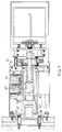
- Figures 5 and 6 which are both elevation views in cross-sectional form, further embodiments are illustrated providing the further advantage of the ability to remove the detector head 30 without breaking the vacuum in the dewar 1 and in the transition means 40. Consequently, after an assembly operation, a user may immediately begin the cooling operation. It is not necessary to perform the intermediate step of evacuating the vacuum-jacket 11 in chambers with which it communicates.
- Figures 5 and 6 the same reference numerals are utilized to denote corresponding components in the detector head assembly 30 and the dewar 1. Primed numbers indicate components varying structure from the embodiment of Figures 1-3 but functioning similarly. In the embodiments of Figures 5 and 6, the most significant differences are in the area of the receptacle means 44.
- the rod 45 is formed with a thread 48 to thread into a thread 47 in the base 42.
- a transition bellows member 70 is further provided disposed to close the evacuatable chamber 55 even when the detector assembly 20 is detached from the cooling rod housing assembly 52 so long as the housing member 54 is fixed with respect to the cooling rod assembly 41. Since chambers 12 and 55 are kept sealed, a user will be able to cool immediately a newly assembled detector system without first vacuum pumping the chambers 55 and 12 with an external pump.
- a thread 72 may be provided for the axial end of the housing member 54 to the base 28 of the detector head assembly 20.
- the recess 29 in the base 28 comprises a thread 73 for receiving the thread 72.
- a thermal clamp is provided.
- the difference of thermal coefficient of expansion between titanium and aluminum parts produces a radially directed force from the receptacle means 44 on the conducting rod 35.
- the bellows 70 is thin walled stainless steel.
- the necessary air interface between the bellows 70 and the bellows 36 may be as small as 0.15 cubic inch.
- a further form of bellows 75 is provided to close the vacuum path.
- a cavity 79 in the central portion of the cooling rod 45′ is constructed for receiving a double acting cooling rod clamp 80.
- the double acting cooling rod clamp 80 works in conjunction with a receptacle 44′ and a conducting rod 35′, each of which have a larger inner diameter than the clamp 80 when the system is at room temperature.
- the clamp 80 is partially received in an annular end of the conducting rod 35′.
- the receptacle 44′ surrounds an outer diameter of the clamp 80 along a first axial portion and surrounds the annular end of the conducting rod 35′ which receives the remainder of the clamp.
- the clamp member 80 utilizes invar in opposition to aluminum or magnesium instead of titanium in opposition to aluminum.
- the bellows member 75 is a stainless steel bellows.
- a sieve pack 85 is placed in the remainder of the cavity also receiving the clamp member 80 for use in creating from atmospheric pressure a vacuum therein.
- a clamp member 88 may be used to similarly releasably engage the cylinder 43 to the base portion 42 of the transition member 41.
- a glass fiber-epoxy sleeve extends axially from an area near the clamp 88 to the base 28 of the detector head 30 to define an inner wall of the chamber 55.
- transition assembly 40 incorporating a further form of cooling rod 45 referred to in Figure 7 as 45 ⁇ .
- the cooling rod 45 ⁇ has a first axial portion adjacent to the dewar 1 for mating with a clamp member 88′
- the clamp member 88′ is preferably of invar and surrounded by a copper sleeve 89′.
- the base 42 ⁇ is formed to receive a first axial portion of clamp 88′ and sleeve 89′. The remainder thereof is received within a recess in the first axial portion of the cooling rod 45 ⁇ .
- a second axial portion of the cooling rod 45 ⁇ is of reduced diameter with respect to the first axial portion thereof and is for receiving within a cylindrical recess an end of conducting rod 35 ⁇ also having a cylindrical recess.
- a clamp member 80 ⁇ is received in the cylindrical recess at the end of the conducting rod 35 ⁇ and is also in axial registration with the second axial end of the cooling rod 45 ⁇ .
- the remainder of the cylindrical recess contains a charcoal pack 85 ⁇ . As the system is cooled to operating temperature, the clamp 80 ⁇ forces the cooling rod 45 ⁇ into a force fit with the conducting rod 35 ⁇ and the charcoal pack 85 ⁇ pumps the recess to vacuum.
- the fiber glass and epoxy sleeve 81′ extending from the first axial portion of the cooling rod 45 ⁇ to the portion of the sleeve 52 ⁇ received in the recess 28 is bonded thereto.
- the specification has been written with a view toward enabling those skilled in the art to produce photon detector assemblies, cryostats, transition assemblies and subassemblies thereof.
- Other forms of the cooling rod can be provided consistent with the philosophy of maintaining good mechanical and thermal communication between the dewar and conducting rod and maintaining minimal air volume therearound.
- a vacuum chamber common to the dewar and transition assembly is provided which in some embodiments need not be vented to the atmosphere to provide for change of detector heads. The detector does not have to be removed from its vacuum enclosure to be changed from one cryostat to another or to be moved from cooperation with one dewar to another.
Claims (7)
- Système de détecteur de photons comprenant deux portions relativement détachables (1, 2), la première portion comprenant un flacon à vide possèdant une enceinte (10) pour contenir du fluide cryogénique et une chemise à vide (12) autour de l'enceinte, la seconde portion comprenant un détecteur (21) et une chemise à vide (30) autour du détecteur, des premier et second capteurs de transition (41, 52) pour l'accouplement thermique des portions, chaque capteur possédant un tube, le tube (52) d'un capteur étant construit et agencé pour encercler le tube (45) de l'autre capteur pour former une enceinte annulaire (55) avec celui-là, les tubes possédant chacun une base associée à partir de laquelle ils s'étendent, la base (53) du premier capteur raccordant la chemise à vide (12) du flacon à l'enceinte annulaire (55), des moyens (28, 29) étant montés sur la seconde portion pour fermer l'enceinte annulaire, la base (42) de l'autre capteur étant raccordée thermiquement à l'enceinte (10), un membre de conduction thermique (44) dans le tube de l'autre capteur et raccordé thermiquement à la base (42), et une jonction thermique raccordant ledit membre (44) à un membre (35) raccordé thermiquement au détecteur (21), caractérisé en ce que la chemise à vide (30) est fermée de manière étanche, et le membre (44) et le membre (35) sont construits pour avoir des dimensions et des coéfficients thermiques d'expansion tels qu'ils sont engageables de manière libérable à une première température ambiante et qu'une force de serrage radiale est appliquée entre ceux-ci après le refroidissement du membre (44) en réponse au fluide cryogénique dans ladite enceinte (10).
- Système selon la revendication 1, dans lequel la jonction thermique est formée du fait que ledit membre (44) présente une extrémité comportant une cavité pour recevoir une saillie du membre (35).
- Système selon la revendication 1 ou la revendication 2, dans lequel le détecteur (21) comprend une portion de base (28), ledit membre de conduction (35) étant monté sur ladite portion de base et étant entouré par un moyen de joint de compression (56) définissant ladite chemise (30).
- Système selon la revendication 3, comprenant en outre un moyen de joint à soufflet (36) raccordé entre ladite portion de base (28) et l'extrémité à cavité du membre (44).
- Système selon l'une quelconque des revendications 1 à 4, comprenant en outre un moyen d'enveloppe (60) entourant lesdits capteurs de transition (41, 52) et renfermant un volume entre ledit moyen à détecteur (21) et ladite enceinte (10) pour définir une enceinte fermée entre ceux-ci.
- Système selon la revendication 5, comprenant en outre un moyen de circuit (58) pour être monté à l'intérieur du moyen d'enveloppe (60).
- Système selon l'une quelconque des revendications 1 à 6, dans lequel lesdits capteurs de transition (41, 52) définissent trois enceintes capables d'être mises sous vide, une première enceinte comprenant ladite enceinte (55), une seconde enceinte comprenant l'espace à l'intérieur dudit tube (45), et une troisième enceinte comprenant une enceinte à l'intérieur dudit tube (52) et à l'extérieur desdits moyens (28, 29).
Applications Claiming Priority (5)
| Application Number | Priority Date | Filing Date | Title |
|---|---|---|---|
| GB8607356 | 1986-03-25 | ||
| GB8607356A GB8607356D0 (en) | 1986-03-25 | 1986-03-25 | Modular cryogenic detector head assembly |
| US28636 | 1987-03-20 | ||
| US07/028,636 US4851684A (en) | 1986-03-25 | 1987-03-20 | Modular photon detector cryostat assembly and system |
| PCT/US1987/000645 WO1987005990A1 (fr) | 1986-03-25 | 1987-03-24 | Systeme et ensemble de cryostat modulaire a detecteur de photons |
Publications (3)
| Publication Number | Publication Date |
|---|---|
| EP0265486A1 EP0265486A1 (fr) | 1988-05-04 |
| EP0265486A4 EP0265486A4 (en) | 1991-05-22 |
| EP0265486B1 true EP0265486B1 (fr) | 1994-10-05 |
Family
ID=26290535
Family Applications (1)
| Application Number | Title | Priority Date | Filing Date |
|---|---|---|---|
| EP19870902944 Expired - Lifetime EP0265486B1 (fr) | 1986-03-25 | 1987-03-24 | Systeme et ensemble de cryostat modulaire a detecteur de photons |
Country Status (4)
| Country | Link |
|---|---|
| EP (1) | EP0265486B1 (fr) |
| AT (1) | ATE112622T1 (fr) |
| DE (1) | DE3750626T2 (fr) |
| WO (1) | WO1987005990A1 (fr) |
Cited By (1)
| Publication number | Priority date | Publication date | Assignee | Title |
|---|---|---|---|---|
| CN103728651A (zh) * | 2013-12-12 | 2014-04-16 | 西北核技术研究所 | 一种具有热净化功能的高纯锗探测器真空维护系统 |
Families Citing this family (5)
| Publication number | Priority date | Publication date | Assignee | Title |
|---|---|---|---|---|
| DE4324710A1 (de) * | 1993-07-23 | 1995-01-26 | Forschungszentrum Juelich Gmbh | Verfahren zum Herstellen eines gekapselten Detektors |
| GB0408425D0 (en) | 2004-04-15 | 2004-05-19 | Oxford Instr Superconductivity | Cooling apparatus |
| GB201215919D0 (en) | 2012-09-06 | 2012-10-24 | Johnson Matthey Plc | Radiation detector |
| DE102014223831A1 (de) | 2014-11-21 | 2016-05-25 | France Canberra | Aufnahmebehälter für einen in einem Ultrahochvakuum oder in einer Schutzgasatmosphäre aus hochreinem Gas arbeitenden Detektor |
| EP4365521A1 (fr) * | 2022-11-05 | 2024-05-08 | kiutra GmbH | Appareil cryogénique |
Family Cites Families (9)
| Publication number | Priority date | Publication date | Assignee | Title |
|---|---|---|---|---|
| US3483709A (en) * | 1967-07-21 | 1969-12-16 | Princeton Gamma Tech Inc | Low temperature system |
| DE1751051C3 (de) * | 1968-03-26 | 1974-01-03 | Siemens Ag, 1000 Berlin U. 8000 Muenchen | Kryostat mit einer Vakuumkammer |
| DE1931581A1 (de) * | 1969-06-21 | 1970-12-23 | Philips Nv | Kryostatdetektor |
| DE2162845A1 (de) * | 1970-12-22 | 1972-07-13 | Commissariat Energie Atomique | Kryostatische Untersuchungsvorrichtung |
| GB1375434A (fr) * | 1971-01-28 | 1974-11-27 | ||
| US3807188A (en) * | 1973-05-11 | 1974-04-30 | Hughes Aircraft Co | Thermal coupling device for cryogenic refrigeration |
| US3851173A (en) * | 1973-06-25 | 1974-11-26 | Texas Instruments Inc | Thermal energy receiver |
| US4218892A (en) * | 1979-03-29 | 1980-08-26 | Nasa | Low cost cryostat |
| US4324104A (en) * | 1980-04-03 | 1982-04-13 | The United States Of America As Represented By The Secretary Of The Army | Noncontact thermal interface |
-
1987
- 1987-03-24 EP EP19870902944 patent/EP0265486B1/fr not_active Expired - Lifetime
- 1987-03-24 DE DE19873750626 patent/DE3750626T2/de not_active Expired - Fee Related
- 1987-03-24 AT AT87902944T patent/ATE112622T1/de not_active IP Right Cessation
- 1987-03-24 WO PCT/US1987/000645 patent/WO1987005990A1/fr active IP Right Grant
Cited By (1)
| Publication number | Priority date | Publication date | Assignee | Title |
|---|---|---|---|---|
| CN103728651A (zh) * | 2013-12-12 | 2014-04-16 | 西北核技术研究所 | 一种具有热净化功能的高纯锗探测器真空维护系统 |
Also Published As
| Publication number | Publication date |
|---|---|
| DE3750626D1 (de) | 1994-11-10 |
| DE3750626T2 (de) | 1995-04-27 |
| ATE112622T1 (de) | 1994-10-15 |
| WO1987005990A1 (fr) | 1987-10-08 |
| EP0265486A1 (fr) | 1988-05-04 |
| EP0265486A4 (en) | 1991-05-22 |
Similar Documents
| Publication | Publication Date | Title |
|---|---|---|
| US4851684A (en) | Modular photon detector cryostat assembly and system | |
| US7161150B2 (en) | Handheld isotope identification system | |
| US6122919A (en) | Sensor/cooling system with cold finger having recessed end | |
| US5494033A (en) | Biomagnetometer with sealed vacuum enclosure and solid conduction cooling | |
| EP0464893B1 (fr) | Détecteurs aux infrarouges et leur préparation | |
| EP0265486B1 (fr) | Systeme et ensemble de cryostat modulaire a detecteur de photons | |
| US4241592A (en) | Cryostat for borehole sonde employing semiconductor detector | |
| US4501131A (en) | Cryogenic cooler for photoconductive cells | |
| US7064337B2 (en) | Radiation detection system for portable gamma-ray spectroscopy | |
| EP0136687A2 (fr) | Détecteur de rayonnement infra-rouge | |
| EP0115698B1 (fr) | Détecteur de rayonnement réfrigéré | |
| US3394258A (en) | Apparatus for thermally measuring absorbed radiation doses | |
| US5111049A (en) | Remote fired RF getter for use in metal infrared detector dewar | |
| GB2015716A (en) | Cryostat with radiation shield | |
| CA1265346A (fr) | Ensemble detecteur a disque sous chambre a depression | |
| US5235184A (en) | Highly stable low noise CCD spectrograph | |
| EP0253883B1 (fr) | Dispositif detecteur de radiations a refroidissement cryogenique | |
| US2973434A (en) | Infrared detecting cell and a mounting therefor | |
| US3259865A (en) | Dewar for cryogenic cooling of solid state device | |
| EP0213421A2 (fr) | Détecteur infrarouge comprenant des cavités sous vide | |
| US5604349A (en) | Capsule for a detector operating in an ultra-high vacuum | |
| JPH05500266A (ja) | 組み込み形式の光検出器低温保持装置組立て体および装置 | |
| US5225677A (en) | Protective film for x-ray detector | |
| Miner | A semiconductor detector cryostat | |
| US4661707A (en) | Disc detector assembly having prefabricated vacuum chambers |
Legal Events
| Date | Code | Title | Description |
|---|---|---|---|
| PUAI | Public reference made under article 153(3) epc to a published international application that has entered the european phase |
Free format text: ORIGINAL CODE: 0009012 |
|
| AK | Designated contracting states |
Kind code of ref document: A1 Designated state(s): AT BE CH DE FR GB IT LI LU NL SE |
|
| 17P | Request for examination filed |
Effective date: 19880406 |
|
| R17P | Request for examination filed (corrected) |
Effective date: 19880406 |
|
| A4 | Supplementary search report drawn up and despatched |
Effective date: 19910404 |
|
| AK | Designated contracting states |
Kind code of ref document: A4 Designated state(s): AT BE CH DE FR GB IT LI LU NL SE |
|
| 17Q | First examination report despatched |
Effective date: 19920225 |
|
| GRAA | (expected) grant |
Free format text: ORIGINAL CODE: 0009210 |
|
| RAP1 | Party data changed (applicant data changed or rights of an application transferred) |
Owner name: EG&G INSTRUMENTS, INC. |
|
| AK | Designated contracting states |
Kind code of ref document: B1 Designated state(s): AT BE CH DE FR GB IT LI LU NL SE |
|
| PG25 | Lapsed in a contracting state [announced via postgrant information from national office to epo] |
Ref country code: IT Free format text: LAPSE BECAUSE OF FAILURE TO SUBMIT A TRANSLATION OF THE DESCRIPTION OR TO PAY THE FEE WITHIN THE PRE;WARNING: LAPSES OF ITALIAN PATENTS WITH EFFECTIVE DATE BEFORE 2007 MAY HAVE OCCURRED AT ANY TIME BEFORE 2007. THE CORRECT EFFECTIVE DATE MAY BE DIFFERENT FROM THE ONE RECORDED.SCRIBED TIME-LIMIT Effective date: 19941005 Ref country code: AT Effective date: 19941005 Ref country code: LI Effective date: 19941005 Ref country code: NL Effective date: 19941005 Ref country code: CH Effective date: 19941005 |
|
| REF | Corresponds to: |
Ref document number: 112622 Country of ref document: AT Date of ref document: 19941015 Kind code of ref document: T |
|
| REF | Corresponds to: |
Ref document number: 3750626 Country of ref document: DE Date of ref document: 19941110 |
|
| PG25 | Lapsed in a contracting state [announced via postgrant information from national office to epo] |
Ref country code: SE Effective date: 19950105 |
|
| ET | Fr: translation filed | ||
| REG | Reference to a national code |
Ref country code: CH Ref legal event code: PL |
|
| NLV1 | Nl: lapsed or annulled due to failure to fulfill the requirements of art. 29p and 29m of the patents act | ||
| PG25 | Lapsed in a contracting state [announced via postgrant information from national office to epo] |
Ref country code: GB Effective date: 19950324 |
|
| PG25 | Lapsed in a contracting state [announced via postgrant information from national office to epo] |
Ref country code: LU Free format text: LAPSE BECAUSE OF NON-PAYMENT OF DUE FEES Effective date: 19950331 |
|
| PLBE | No opposition filed within time limit |
Free format text: ORIGINAL CODE: 0009261 |
|
| STAA | Information on the status of an ep patent application or granted ep patent |
Free format text: STATUS: NO OPPOSITION FILED WITHIN TIME LIMIT |
|
| 26N | No opposition filed | ||
| GBPC | Gb: european patent ceased through non-payment of renewal fee |
Effective date: 19950324 |
|
| PGFP | Annual fee paid to national office [announced via postgrant information from national office to epo] |
Ref country code: FR Payment date: 20000214 Year of fee payment: 14 |
|
| PGFP | Annual fee paid to national office [announced via postgrant information from national office to epo] |
Ref country code: DE Payment date: 20000228 Year of fee payment: 14 |
|
| PGFP | Annual fee paid to national office [announced via postgrant information from national office to epo] |
Ref country code: BE Payment date: 20000313 Year of fee payment: 14 |
|
| PG25 | Lapsed in a contracting state [announced via postgrant information from national office to epo] |
Ref country code: BE Free format text: LAPSE BECAUSE OF NON-PAYMENT OF DUE FEES Effective date: 20010331 |
|
| BERE | Be: lapsed |
Owner name: EG&G INSTRUMENTS INC. Effective date: 20010331 |
|
| PG25 | Lapsed in a contracting state [announced via postgrant information from national office to epo] |
Ref country code: FR Free format text: LAPSE BECAUSE OF NON-PAYMENT OF DUE FEES Effective date: 20011130 |
|
| REG | Reference to a national code |
Ref country code: FR Ref legal event code: ST |
|
| PG25 | Lapsed in a contracting state [announced via postgrant information from national office to epo] |
Ref country code: DE Free format text: LAPSE BECAUSE OF NON-PAYMENT OF DUE FEES Effective date: 20020101 |