EP0265270A2 - A non throttling discharge pump assembly - Google Patents
A non throttling discharge pump assembly Download PDFInfo
- Publication number
- EP0265270A2 EP0265270A2 EP87309364A EP87309364A EP0265270A2 EP 0265270 A2 EP0265270 A2 EP 0265270A2 EP 87309364 A EP87309364 A EP 87309364A EP 87309364 A EP87309364 A EP 87309364A EP 0265270 A2 EP0265270 A2 EP 0265270A2
- Authority
- EP
- European Patent Office
- Prior art keywords
- piston
- cylinder
- pump assembly
- valve member
- fluid
- Prior art date
- Legal status (The legal status is an assumption and is not a legal conclusion. Google has not performed a legal analysis and makes no representation as to the accuracy of the status listed.)
- Granted
Links
- 239000012530 fluid Substances 0.000 claims abstract description 49
- 230000009471 action Effects 0.000 claims description 16
- 238000007789 sealing Methods 0.000 claims description 13
- 230000006835 compression Effects 0.000 claims description 6
- 238000007906 compression Methods 0.000 claims description 6
- 230000001419 dependent effect Effects 0.000 claims description 2
- 229940126601 medicinal product Drugs 0.000 abstract 1
- 230000000994 depressogenic effect Effects 0.000 description 9
- 239000007789 gas Substances 0.000 description 7
- 239000007788 liquid Substances 0.000 description 7
- 230000037452 priming Effects 0.000 description 7
- 239000000047 product Substances 0.000 description 7
- 230000000717 retained effect Effects 0.000 description 4
- 230000000712 assembly Effects 0.000 description 3
- 238000000429 assembly Methods 0.000 description 3
- 239000000463 material Substances 0.000 description 3
- 230000037361 pathway Effects 0.000 description 3
- IJGRMHOSHXDMSA-UHFFFAOYSA-N Atomic nitrogen Chemical compound N#N IJGRMHOSHXDMSA-UHFFFAOYSA-N 0.000 description 2
- CURLTUGMZLYLDI-UHFFFAOYSA-N Carbon dioxide Chemical compound O=C=O CURLTUGMZLYLDI-UHFFFAOYSA-N 0.000 description 2
- 230000008901 benefit Effects 0.000 description 2
- 239000004033 plastic Substances 0.000 description 2
- 229920003023 plastic Polymers 0.000 description 2
- MGWGWNFMUOTEHG-UHFFFAOYSA-N 4-(3,5-dimethylphenyl)-1,3-thiazol-2-amine Chemical compound CC1=CC(C)=CC(C=2N=C(N)SC=2)=C1 MGWGWNFMUOTEHG-UHFFFAOYSA-N 0.000 description 1
- 239000004215 Carbon black (E152) Substances 0.000 description 1
- 238000000889 atomisation Methods 0.000 description 1
- 229910002092 carbon dioxide Inorganic materials 0.000 description 1
- 239000001569 carbon dioxide Substances 0.000 description 1
- 230000008859 change Effects 0.000 description 1
- 238000002788 crimping Methods 0.000 description 1
- 230000009977 dual effect Effects 0.000 description 1
- 230000000694 effects Effects 0.000 description 1
- NBVXSUQYWXRMNV-UHFFFAOYSA-N fluoromethane Chemical compound FC NBVXSUQYWXRMNV-UHFFFAOYSA-N 0.000 description 1
- 230000005484 gravity Effects 0.000 description 1
- 229930195733 hydrocarbon Natural products 0.000 description 1
- 150000002430 hydrocarbons Chemical class 0.000 description 1
- 230000006872 improvement Effects 0.000 description 1
- 239000012263 liquid product Substances 0.000 description 1
- 229910052757 nitrogen Inorganic materials 0.000 description 1
- JCXJVPUVTGWSNB-UHFFFAOYSA-N nitrogen dioxide Inorganic materials O=[N]=O JCXJVPUVTGWSNB-UHFFFAOYSA-N 0.000 description 1
- 239000003380 propellant Substances 0.000 description 1
- 239000012047 saturated solution Substances 0.000 description 1
Images


Classifications
-
- B—PERFORMING OPERATIONS; TRANSPORTING
- B05—SPRAYING OR ATOMISING IN GENERAL; APPLYING FLUENT MATERIALS TO SURFACES, IN GENERAL
- B05B—SPRAYING APPARATUS; ATOMISING APPARATUS; NOZZLES
- B05B11/00—Single-unit hand-held apparatus in which flow of contents is produced by the muscular force of the operator at the moment of use
- B05B11/01—Single-unit hand-held apparatus in which flow of contents is produced by the muscular force of the operator at the moment of use characterised by the means producing the flow
- B05B11/10—Pump arrangements for transferring the contents from the container to a pump chamber by a sucking effect and forcing the contents out through the dispensing nozzle
- B05B11/1042—Components or details
- B05B11/1073—Springs
- B05B11/1074—Springs located outside pump chambers
-
- B—PERFORMING OPERATIONS; TRANSPORTING
- B05—SPRAYING OR ATOMISING IN GENERAL; APPLYING FLUENT MATERIALS TO SURFACES, IN GENERAL
- B05B—SPRAYING APPARATUS; ATOMISING APPARATUS; NOZZLES
- B05B11/00—Single-unit hand-held apparatus in which flow of contents is produced by the muscular force of the operator at the moment of use
- B05B11/0005—Components or details
- B05B11/0059—Components or details allowing operation in any orientation, e.g. for discharge in inverted position
-
- B—PERFORMING OPERATIONS; TRANSPORTING
- B05—SPRAYING OR ATOMISING IN GENERAL; APPLYING FLUENT MATERIALS TO SURFACES, IN GENERAL
- B05B—SPRAYING APPARATUS; ATOMISING APPARATUS; NOZZLES
- B05B11/00—Single-unit hand-held apparatus in which flow of contents is produced by the muscular force of the operator at the moment of use
- B05B11/0005—Components or details
- B05B11/0097—Means for filling or refilling the sprayer
-
- B—PERFORMING OPERATIONS; TRANSPORTING
- B05—SPRAYING OR ATOMISING IN GENERAL; APPLYING FLUENT MATERIALS TO SURFACES, IN GENERAL
- B05B—SPRAYING APPARATUS; ATOMISING APPARATUS; NOZZLES
- B05B11/00—Single-unit hand-held apparatus in which flow of contents is produced by the muscular force of the operator at the moment of use
- B05B11/01—Single-unit hand-held apparatus in which flow of contents is produced by the muscular force of the operator at the moment of use characterised by the means producing the flow
- B05B11/10—Pump arrangements for transferring the contents from the container to a pump chamber by a sucking effect and forcing the contents out through the dispensing nozzle
- B05B11/1001—Piston pumps
- B05B11/1023—Piston pumps having an outlet valve opened by deformation or displacement of the piston relative to its actuating stem
- B05B11/1026—Piston pumps having an outlet valve opened by deformation or displacement of the piston relative to its actuating stem the piston being deformable and its deformation allowing opening of the outlet
-
- B—PERFORMING OPERATIONS; TRANSPORTING
- B05—SPRAYING OR ATOMISING IN GENERAL; APPLYING FLUENT MATERIALS TO SURFACES, IN GENERAL
- B05B—SPRAYING APPARATUS; ATOMISING APPARATUS; NOZZLES
- B05B11/00—Single-unit hand-held apparatus in which flow of contents is produced by the muscular force of the operator at the moment of use
- B05B11/01—Single-unit hand-held apparatus in which flow of contents is produced by the muscular force of the operator at the moment of use characterised by the means producing the flow
- B05B11/10—Pump arrangements for transferring the contents from the container to a pump chamber by a sucking effect and forcing the contents out through the dispensing nozzle
- B05B11/1038—Pressure accumulation pumps, i.e. pumps comprising a pressure accumulation chamber
- B05B11/1039—Pressure accumulation pumps, i.e. pumps comprising a pressure accumulation chamber the outlet valve being mechanically opened after a defined accumulation stroke
Definitions
- This invention relates to a pump assembly for an atomising piston pump.
- a pump assembly comprising a piston slidably located in a cylinder, a variable volume fluid storage chamber in communication with the cylinder on one side of the piston, means for varying the volume of the chamber, resilient means urging the varying means into a position corresponding to the minimum volume of the chamber, a fluid flow passageway through the piston, valve means for opening and closing the passageway and means for opening the valve means only after the piston has moved relatively to the cylinder by a predetermined amount greater than zero.
- This type of pump assembly is known for example from United Kingdom Patent 1499325.
- Such pump assemblies are referred to as being of the non throttling type since the flow of fluid during discharge is independent of any bias applied to the piston by the operator of the pump whereas in so called throttling type of pump assembly the flow may be varied by a throttling action dependent upon the bias applied to the piston by finger pressure for example.
- a pump assembly for an atomising piston pump comprising a piston slidably located in a cylinder, a variable volume fluid storage chamber in communication with the cylinder on one side of the piston, means for varying the volume of the chamber, resilient means urging the varying means into a position corresponding to the minimum volume of the chamber, a fluid flow passageway through the piston, a resilient valve member normally closing the passageway and deforming means for deforming the valve member so as to open the passageway only after the piston has moved relative to the cylinder by a predetermined amount greater than zero.
- An advantage of such an arrangement is that the need for a complex multicomponent valve means including a spring biassing the valve means into the closed position is obviated.
- the piston includes a cylindrical surface in which an aperture of the passageway is formed and the resilient valve member includes a sleeve portion which overlays the surface and normally obturates the aperture, which sleeve portion is axially compressible by the deforming means so as to at least partially uncover the aperture and thereby open the passageway.
- the resilient valve member is mounted coaxially upon and moveably with the piston and further comprises a piston ring portion of larger radius than the sleeve portion, which piston ring portion forms a seal between the pistion and the cylinder throughout at least part of the piston stroke.
- the piston ring portion is located at or adjacent to a first axial extremity of the sleeve portion, the valve member being orientated such that a second axial extremity of the sleeve portion precedes the first extremity during the compression stroke of the piston into the cylinder.
- valve member performs a dual function of sealing the piston to the cylinder and providing valve action to open and close the passageway. The complexity and number of components is thereby further reduced.
- the cylinder has a first end adjacent the piston in its position of rest between operating periods of the pump assembly and a second end adjacent the piston in its position of maximum travel during operation of the pump assembly and the cylinder is open at both first and second ends for filling with fluid whilst the piston is in its rest position.
- the pump assembly may therefore be self priming since gas may escape from one end of the cylinder whilst liquid fills through the other end by gravity filling for example.
- the cylinder further includes a bypass channel at the first end which provides a flow path bypassing the seal provided by the piston ring portion when the piston is in its rest position whereby the cylinder is then open at its first end.
- the pump assembly may have a valve member wherein the piston ring portion provides a seal between the piston and the cylinder throughout the stroke of the piston and the cylinder is open at its second end for filling with fluid when the piston is in its rest position between operating periods of the pump assembly.
- This type of arrangement could be used for example in providing a pump assembly for a vented container (i.e. open to atmospheric pressure) so that in use the container remained upright with the stem of the pump assembly uppermost.
- the deforming means comprises abutment means extending inwardly of the cylinder and engageable in abutment with the valve member when the piston has moved by the predetermined amount such that continued movement of the piston deforms a valve member.
- the abutment means comprises an annular insert located in the cylinder so as to provide a radially inwardly directed projection for abutment with the valve member.
- the piston comprises an elongate body portion having a front end extending into the cylinder and a projecting portion which is connected coaxially therewith to the front end by means of the valve member so as to be longitudinally moveable relative to the body portion by deformation of the valve member, the cylinder having at its second end an abutment means engageable in abutment with the projecting portion when the piston has moved relative to the cylinder by the predetermined amount, which abutment means and projecting portion together constitute the valve member deforming means.
- the body portion in such an arrangement is tubular and the projecting portion is tubular having a closed end adjacent to and nestable within the body portion, the projecting portion having a radially extending port having an aperture in its outer cylindrical surface which is normally closed by the valve member and opened by action of the deformation means to deform the valve member, the arrangement being such that when the aperture is open the projection portion, the port and the body portion define an open passageway through the piston and when the aperture is closed the passageway is closed by the valve member.
- FIG. 1 shows a pump assembly 1 comprising a housing 2 of a plastics material to which a metallic cup 3 is attached by crimping.
- the housing 2 comprises a cylinder 4 and a secondary cylinder 5 of smaller diameter which is connected contiguously and coaxially with the cylinder 4 by a tapered neck 6.
- the housing 2 is externally enlarged adjacent a first end 7 of the cylinder 4 to provide an annular base 8 upon which the cup 3 is mounted.
- a tubular stem 9 extends through a central orifice 10 in both the cup 3 and the base 8 so as to extend into the cylinder 4 and is retained by an annular flange 11 of larger radius than the orifice 10.
- the stem 9 has an innermost end 12 with respect to the cylinder 4 within which circumferentially spaced axially extending ribs 35 project radially inwards of the inner surface.
- a cylindrical member 13 extends axially into the innermost end 12 to an extent limited by an annular stop 14 projecting from the member at its mid point so that a projecting portion 15 of the member extends into the cylinder 4. The member 13 is frictionally retained within the innermost end 12 of the stem 9 by contact with the ribs 35.
- the secondary cylinder 5 houses a helical compression spring 17 which biasses a secondary piston 18 towards the neck 6 by reaction of the spring against a seat 19 at the remote end 20 of the secondary cylinder.
- the secondary cylinder 5 and the secondary piston 18 together comprise a variable volume storage chamber which is shown in Figure 1 in its condition of having a minimum (zero) volume forward of the secondary piston 18.
- a port 21 is provided in the seat 19 for the admission of fluid rearward of the secondary piston 18.
- the secondary piston 18 includes a deformable annular outer collar 22 at its forward end which seals the secondary piston against the secondary cylinder 5 during forward motion of the secondary piston.
- the outer collar 22 is frusto conically profiled so as to taper in a direction away from the cylinder 4.
- the piston 16 is in its rest position adjacent the first end of the cylinder 4 with the spring 17 being fully extended so that the secondary piston 18 is held in contact with the projecting portion 15.
- the outer collar 22 of the secondary piston 18 is external to the secondary cylinder 5 and is spaced from the neck 6 by webs 23 which extend longitudinally of and radially inward of the housing 2 at the second end 24 of the cylinder 4.
- a fluid pathway into the cylinder 4 then exists through the port 21, the interior of the secondary cylinder 5, between the webs 23 and into the cylinder 4 at its second end 24.
- a resilient valve member 25 is mounted coaxially upon the stem 9 within the cylinder 4 so as to be captively retained axially between the flange 11 and the stop 14.
- the valve member 25 comprises a sleeve portion 26 having at one end a radially extending piston ring portion 27 adjacent the stop 14.
- the piston ring portion 27 forms a seal between the piston 16 and the cylinder 4 which in the rest position as shown in Figure 1 is bypassed by an axially extending groove 28 on one side of the cylinder wall so as to form a bypass channel communicating with a vent 29 extending through the housing 2.
- the stem 9 includes an axially extending passageway 30 communicating with an aperture 31 formed in the outer cylindrical surface 36 of the stem 9 at its innermost end 12 with respect to the chamber 4.
- the ribs 35 serve to space the cylindrical member 13 from the internal wall of the stem 9 so that the passageway 30 is not blocked by this member.
- the aperture 31 is closed by the valve member 25 so that there is no communication through the passageway 30 into the cylinder 4.
- a sealing gasket 32 surrounds the stem 9 at its point of entry to the cup 3 so as to provide a fluid tight seal and the stem 9 is a loose fit within the orifice 10 in the cup 3 such that an annular gap 33 is defined therebetween.
- the gasket 32 is periferally clamped between the outer side of the base 8 and the inner side of the cup 3.
- a further seal 34 is provided on the opposite side of the base 8 and external to the cylinder 4 so that in attaching the cup 3 to the lip of a container (not shown) the further seal 34 provides a fluid tight seal between the lip and the base.
- the pump assembly 1 is shown in Figure 1 in an inverted position in which the stem 9 is downwardly directed in readiness for dispensing of a liquid product containing in the container (not shown).
- liquid from the container enters the cylinder 4 through the vent 29 and groove 28 whilst any trapped gas within the cylinder 4 is vented upwardly through the second end 24 of the cylinder 4 to emerge from the port 21.
- the pump assembly is therefore self priming simply by placing the container and pump assembly in the inverted position as shown in Figure 1.
- Figure 7 shows the manner in which the pump assembly 1 of Figures 1 to 6 enables the container (not shown) to be filled after assembly with the pump assembly 1.
- a filling head 50 is shown in engagement with the pump assembly 1 which has been inverted with respect to its position shown in Figures 1 to 6 so as to be on top of an upright container.
- the filling head 50 comprises a sealing ring 51 which is pressed into sealing engagement with the cup 3 so as to surround the stem 9 and includes a filling duct 52 through which the pressurised fluid is delivered.
- the fluid delivered from the filling head 50 will generally be a propellant material for pressurising a product already partially filling the container. Alternatively in some applications it may be desirable to deliver the product itself via the filling head and where the product is to be pressurised within the container the pressurising gas may be delivered in saturated solution within the product.
- the filling duct 52 is a loose fit around the stem 9 such that fluid passes around the stem into the annular gap 33 between the stem and the cup 3.
- the sealing gasket 32 surrounding the stem 9 of the pump assembly deforms under the applied pressure sufficiently to allow fluid to enter the cylinder 4.
- the stem 9 is depressed by a detent 53 extending radially into the filling duct 52 such that the piston 16 moves into a partially depressed position as described above with reference to Figure 2 and a fluid pathway is then established from the filling duct 52, through the annular gap 33, into the first end 7 of the cylinder 4 and through the vent 29 into the container.
- FIG. 8 An alternative pump assembly 60 is shown in Figure 8 in which components corresponding to those of pump assembly 1 are numbered with corresponding numerals where appropriate.
- the alternative pump assembly 60 is suited for use with an upright container (not shown) and is shown in Figure 8 in its non inverted position ready for use.
- valve member 25 In the rest position of the piston 16 the valve member 25 seals completely against the cylinder 4 so that in the rest position the cylinder is open only at its second end 24 by virtue of the secondary piston 18 projecting from the secondary cylinder 5.
- a tubular extension 61 is provided at the remote end of the secondary cylinder 5 and a dip tube (not shown) is locatable within the tubular extension such that the tubular extension and the dip tube together form a conduit communicating between the secondary cylinder 5 and the bottom of the container (not shown) which would normally contain liquid in which the end of the dip tube was immersed.
- the pump action of the pump assembly 60 is similar to that of the pump assembly 1 described above except that the pump assembly 60 is not self priming. When used with a container in which a quantity of liquid partially fills the container with the remaining volume of the container being filled with a gas the pump assembly 60 will initially have both cylinder 4 and secondary cylinder 5 filled with the gap whilst the container is in the upright condition.
- Depression of the piston 16 will result in a quantity of gas being expelled from the cylinder 4 and on completion of the pump cycle (i.e. when the piston returns to its rest position) a partial vacuum formed in the cylinder 4 will be relieved by liquid being drawn through the dip tube and tubular extension 61. After a number of priming pump actions the cylinder 4 will become filled with liquid and subsequent pump actions will dispense the predetermined volume of liquid as required.
- This alternative pump assembly is particularly useful with containers which are vented to air so that they necessarily must be used in an upright position.
- the assembly may alternatively be used with pressurised containers in which the pressurising gas may for example be Nitrogen, Carbon Dioxide, Nitrogen Dioxide or a fluorocarbon or hydrocarbon gas.
- a piston 70 comprises first and second relatively moveable parts 71 and 72 respectively which are connected by a valve member 73 so as to be relatively moveable by deformation of the valve member.
- the first piston part 71 comprises a stem 9 similar to the stem of Figures 1 to 8 in that it extends through a sealing gasket 32 into the cylinder 4 and is retained by a flange 11.
- the first piston part 71 however is truncacted at the flange 11 and includes an annular rib 74 projecting into the cylinder 4 so as to retain the sleeve portion 26 of the valve member 73 in coaxial alignment with the first piston part 71.
- the second piston part 72 is tubular and nestable within the valve member 73 and the first piston part 71.
- a radially extending flange 75 extends from the mid point of the second piston part in abutment with the piston ring portion 27 of the valve member 73.
- a forward end 76 of the second piston part 72 projects towards the secondary cylinder 5 and is held in abutment with the secondary piston 18 under action of the spring 17 such that the first and second piston parts are biassed together with the tubular valve member 73 being held in compression therebetween. This compression is insufficient to deform the valve member 73 which retains its tubular shape in the rest position of the piston 70 and during its initial stages of depression.
- the forward end 76 is castellated to provide gaps 81 between the second piston part 76 and the secondary piston 18 when in mutual contact so that the interior of the second piston part 76 is in fluid communication with the cylinder 4.
- FIG. 11 shows a modified version of the pump assembly 1 of Figures 1 to 7. Components corresponding to those of pump assembly 1 are numbered with corresponding numerals where appropriate in Figure 11.
- the main difference lies in the shape of the valve member 91 which has a sleeve portion 92 coaxially mounted on the stem 9 with a piston ring portion 93 projecting radially from the lower end 95 of the sleeve portion, the lower end being furthermost from the secondary piston 18 and adjacent to the sealing gasket 32.
- An annular flange 94 extends radially inwardly of the upper end 96 in sealing contact with the outer cylindrical surface 36 of the stem 9 so as to normally close the aperture 31.
- the valve member 91 is located axially between a boss 97 of the stem and a stop 14 of the cylindrical member 30. Upon depression of the stem 9 the valve member moves with the piston 16 with the piston ring portion 93 of the valve member 91 in sliding contact with the cylinder 4. After the stem 9 has been depressed by a predetermined distance the flange 94 of the valve member 91 abuts with the webs 23 and continued depression deforms the valve member 91 axially so as to uncover the aperture 31 to thereby discharge the pump assembly 90.
- This arrangement is an improvement over the device shown in Figures 1 to 7 in that pressure and frictional forces acting on the piston ring portion 93 during depression of the stem 9 do not axially compress the sleeve portion 92 so that the valve member 91 cannot be inadvertently deformed by excessive friction or fluid pressure within the chamber 4 as might otherwise occur for instance when the stem 9 is depressed with excessive voilence.
- FIG. 12 shows a further alternative pump assembly 190 which is shown in Figure 12 which shows a modified version of the pump assembly 90 of Figure 11. Components corresponding to those of pump assembly 90 are numbered with corresponding numerals where appropriate.
- the assembly 190 of Figure 12 differs from the pump assembly 90 of Figure 11 in that the selected dimensions of the cylinder 4 and the secondary cylinder 5 are such that their respective diameters differ only marginally.
- An annular insert 200 is therefore included within the cylinder 4 adjacent to its point of connection to the secondary cylinder 5 to thereby enhance the extent of the radially inward projection against which the upper end 96 of the valve member 91 abuts.
- the annular insert 200 comprises a rigid washer of a plastics material which is received as a force fit within the cylinder 4.
- the secondary piston 118 of Figure 12 includes a rearward portion 119 of cruciform cross section which is of narrower diameter than the annular collar 22 and is located within the spring 17.
- the use of such a cruciform cross section has been found to improve the rigidity and dimensional reproducability of the moulded secondary piston 118.
- Each of the above described pump assemblies may be used with an atomising nozzle (not shown) which fits upon the outer end of the stem 9 in known manner.
- the pressure of the dispensed fluid must be matched to the particular type of nozzle utilised.
- the pressure of the dispensed product is determined by the change in volume occuring within the variable volume fluid storage chamber during discharge and by the pressure applied to the fluid therein by the spring 17.
- Pump assemblies in accordance with the present invention may be used in dispensing metered doses of products for medical applications for example and may be used with pressurised or unpressurised containers.
- a pump assembly When it is required to use such a pump assembly with a vented container such that the container must be used in its upright condition then it is appropriate to use the pump assembly of the type disclosed with reference to Figure 8 above which is not self priming.
- the self priming type of pump assembly such as described above with reference to Figures 1 to 7 is appropriate.
Landscapes
- Reciprocating Pumps (AREA)
- Containers And Packaging Bodies Having A Special Means To Remove Contents (AREA)
- Eye Examination Apparatus (AREA)
- Details Of Reciprocating Pumps (AREA)
- Structures Of Non-Positive Displacement Pumps (AREA)
- Closures For Containers (AREA)
- Fluid-Driven Valves (AREA)
- Seal Device For Vehicle (AREA)
- Flow Control (AREA)
- Lubrication Of Internal Combustion Engines (AREA)
- Electrical Discharge Machining, Electrochemical Machining, And Combined Machining (AREA)
- Non-Positive Displacement Air Blowers (AREA)
- Infusion, Injection, And Reservoir Apparatuses (AREA)
Abstract
Description
- This invention relates to a pump assembly for an atomising piston pump.
- It is known to provide such a pump assembly comprising a piston slidably located in a cylinder, a variable volume fluid storage chamber in communication with the cylinder on one side of the piston, means for varying the volume of the chamber, resilient means urging the varying means into a position corresponding to the minimum volume of the chamber, a fluid flow passageway through the piston, valve means for opening and closing the passageway and means for opening the valve means only after the piston has moved relatively to the cylinder by a predetermined amount greater than zero. This type of pump assembly is known for example from United Kingdom Patent 1499325.
- Such pump assemblies are referred to as being of the non throttling type since the flow of fluid during discharge is independent of any bias applied to the piston by the operator of the pump whereas in so called throttling type of pump assembly the flow may be varied by a throttling action dependent upon the bias applied to the piston by finger pressure for example.
- According to the present invention there is disclosed a pump assembly for an atomising piston pump comprising a piston slidably located in a cylinder, a variable volume fluid storage chamber in communication with the cylinder on one side of the piston, means for varying the volume of the chamber, resilient means urging the varying means into a position corresponding to the minimum volume of the chamber, a fluid flow passageway through the piston, a resilient valve member normally closing the passageway and deforming means for deforming the valve member so as to open the passageway only after the piston has moved relative to the cylinder by a predetermined amount greater than zero.
- An advantage of such an arrangement is that the need for a complex multicomponent valve means including a spring biassing the valve means into the closed position is obviated.
- Preferably the piston includes a cylindrical surface in which an aperture of the passageway is formed and the resilient valve member includes a sleeve portion which overlays the surface and normally obturates the aperture, which sleeve portion is axially compressible by the deforming means so as to at least partially uncover the aperture and thereby open the passageway.
- Preferably the resilient valve member is mounted coaxially upon and moveably with the piston and further comprises a piston ring portion of larger radius than the sleeve portion, which piston ring portion forms a seal between the pistion and the cylinder throughout at least part of the piston stroke.
- In a preferred embodiment of the invention the piston ring portion is located at or adjacent to a first axial extremity of the sleeve portion, the valve member being orientated such that a second axial extremity of the sleeve portion precedes the first extremity during the compression stroke of the piston into the cylinder.
- An advantage of such an arrangement is that the valve member performs a dual function of sealing the piston to the cylinder and providing valve action to open and close the passageway. The complexity and number of components is thereby further reduced.
- Advantageously the cylinder has a first end adjacent the piston in its position of rest between operating periods of the pump assembly and a second end adjacent the piston in its position of maximum travel during operation of the pump assembly and the cylinder is open at both first and second ends for filling with fluid whilst the piston is in its rest position.
- The pump assembly may therefore be self priming since gas may escape from one end of the cylinder whilst liquid fills through the other end by gravity filling for example.
- Conveniently where the pump assembly includes a valve member having a piston ring portion the cylinder further includes a bypass channel at the first end which provides a flow path bypassing the seal provided by the piston ring portion when the piston is in its rest position whereby the cylinder is then open at its first end.
- Alternatively the pump assembly may have a valve member wherein the piston ring portion provides a seal between the piston and the cylinder throughout the stroke of the piston and the cylinder is open at its second end for filling with fluid when the piston is in its rest position between operating periods of the pump assembly.
- Such an arrangement will not however be self priming and fluid will fill the cylinder by suction action when the piston returns to its rest position.
- This type of arrangement could be used for example in providing a pump assembly for a vented container (i.e. open to atmospheric pressure) so that in use the container remained upright with the stem of the pump assembly uppermost.
- Conveniently the deforming means comprises abutment means extending inwardly of the cylinder and engageable in abutment with the valve member when the piston has moved by the predetermined amount such that continued movement of the piston deforms a valve member.
- Conveniently the abutment means comprises an annular insert located in the cylinder so as to provide a radially inwardly directed projection for abutment with the valve member.
- Alternatively the piston comprises an elongate body portion having a front end extending into the cylinder and a projecting portion which is connected coaxially therewith to the front end by means of the valve member so as to be longitudinally moveable relative to the body portion by deformation of the valve member, the cylinder having at its second end an abutment means engageable in abutment with the projecting portion when the piston has moved relative to the cylinder by the predetermined amount, which abutment means and projecting portion together constitute the valve member deforming means.
- Conveniently the body portion in such an arrangement is tubular and the projecting portion is tubular having a closed end adjacent to and nestable within the body portion, the projecting portion having a radially extending port having an aperture in its outer cylindrical surface which is normally closed by the valve member and opened by action of the deformation means to deform the valve member, the arrangement being such that when the aperture is open the projection portion, the port and the body portion define an open passageway through the piston and when the aperture is closed the passageway is closed by the valve member.
- Particular embodiments of the present invention will now be disclosed by way of example only and with reference to the accompanying drawings of which:
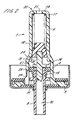
- Figure 1 is a sectional elevation of a pump assembly with the piston in its rest position,
- Figure 2 is a similar view of the assembly of Figure 1 with the piston partially depressed such that the valve member seals between the piston and cylinder,
- Figure 3 is a similar view after further depression of the piston in which fluid is forced into the chamber,
- Figure 4 is a similar view after still further depression of the piston when the valve member first abuts the deforming means,
- Figure 5 is a similar view with the piston fully depressed such that the valve member is deformed to open the passageway,
- Figure 6 is a similar view during discharge of the product by action of the resilient means to reduce the volume within the chamber,
- Figure 7 is a sectional elevation of the pump assembly during filling from a filling head,
- Figure 8 is a sectional elevation of an alternative embodiment of a pump assembly adapted for upright use,
- Figure 9 is a sectional view of part of a further alternative embodiment of a pump assembly in which the piston comprises two relatively moveable components,
- Figure 10 is a similar view of the pump assembly of Figure 9 showing the valve member in its deformed state,
- Figure 11 is a sectional elevation of an alternative pump assembly having a modified valve member, and
- Figure 12 is a similar view of an alternative pump assembly having an annular insert constituting the abutment means.
- Figure 1 shows a
pump assembly 1 comprising ahousing 2 of a plastics material to which ametallic cup 3 is attached by crimping. Thehousing 2 comprises acylinder 4 and asecondary cylinder 5 of smaller diameter which is connected contiguously and coaxially with thecylinder 4 by a tapered neck 6. - The
housing 2 is externally enlarged adjacent afirst end 7 of thecylinder 4 to provide anannular base 8 upon which thecup 3 is mounted. - A
tubular stem 9 extends through acentral orifice 10 in both thecup 3 and thebase 8 so as to extend into thecylinder 4 and is retained by anannular flange 11 of larger radius than theorifice 10. Thestem 9 has aninnermost end 12 with respect to thecylinder 4 within which circumferentially spaced axially extendingribs 35 project radially inwards of the inner surface. Acylindrical member 13 extends axially into theinnermost end 12 to an extent limited by anannular stop 14 projecting from the member at its mid point so that a projectingportion 15 of the member extends into thecylinder 4. Themember 13 is frictionally retained within theinnermost end 12 of thestem 9 by contact with theribs 35. - The
stem 9 and thecylindrical member 13 together comprise apistion 16 which is axially slidable within thecylinder 4. - The
secondary cylinder 5 houses ahelical compression spring 17 which biasses asecondary piston 18 towards the neck 6 by reaction of the spring against aseat 19 at theremote end 20 of the secondary cylinder. Thesecondary cylinder 5 and thesecondary piston 18 together comprise a variable volume storage chamber which is shown in Figure 1 in its condition of having a minimum (zero) volume forward of thesecondary piston 18. - A
port 21 is provided in theseat 19 for the admission of fluid rearward of thesecondary piston 18. Thesecondary piston 18 includes a deformable annularouter collar 22 at its forward end which seals the secondary piston against thesecondary cylinder 5 during forward motion of the secondary piston. Theouter collar 22 is frusto conically profiled so as to taper in a direction away from thecylinder 4. - As shown in Figure 1 the
piston 16 is in its rest position adjacent the first end of thecylinder 4 with thespring 17 being fully extended so that thesecondary piston 18 is held in contact with the projectingportion 15. In this position theouter collar 22 of thesecondary piston 18 is external to thesecondary cylinder 5 and is spaced from the neck 6 bywebs 23 which extend longitudinally of and radially inward of thehousing 2 at thesecond end 24 of thecylinder 4. A fluid pathway into thecylinder 4 then exists through theport 21, the interior of thesecondary cylinder 5, between thewebs 23 and into thecylinder 4 at itssecond end 24. - A
resilient valve member 25 is mounted coaxially upon thestem 9 within thecylinder 4 so as to be captively retained axially between theflange 11 and thestop 14. Thevalve member 25 comprises asleeve portion 26 having at one end a radially extendingpiston ring portion 27 adjacent thestop 14. Thepiston ring portion 27 forms a seal between thepiston 16 and thecylinder 4 which in the rest position as shown in Figure 1 is bypassed by an axially extendinggroove 28 on one side of the cylinder wall so as to form a bypass channel communicating with avent 29 extending through thehousing 2. - In the rest position as shown in Figure 1 a further fluid flow path is established into the
cylinder 4 through thevent 29 and thegroove 28 so that the cylinder is in effect open at both ends. - The
stem 9 includes an axially extendingpassageway 30 communicating with anaperture 31 formed in the outercylindrical surface 36 of thestem 9 at itsinnermost end 12 with respect to thechamber 4. Theribs 35 serve to space thecylindrical member 13 from the internal wall of thestem 9 so that thepassageway 30 is not blocked by this member. In the rest position as shown in Figure 1 theaperture 31 is closed by thevalve member 25 so that there is no communication through thepassageway 30 into thecylinder 4. - A
sealing gasket 32 surrounds thestem 9 at its point of entry to thecup 3 so as to provide a fluid tight seal and thestem 9 is a loose fit within theorifice 10 in thecup 3 such that anannular gap 33 is defined therebetween. Thegasket 32 is periferally clamped between the outer side of thebase 8 and the inner side of thecup 3. - A
further seal 34 is provided on the opposite side of thebase 8 and external to thecylinder 4 so that in attaching thecup 3 to the lip of a container (not shown) thefurther seal 34 provides a fluid tight seal between the lip and the base. - The
pump assembly 1 is shown in Figure 1 in an inverted position in which thestem 9 is downwardly directed in readiness for dispensing of a liquid product containing in the container (not shown). In this inverted position liquid from the container enters thecylinder 4 through thevent 29 and groove 28 whilst any trapped gas within thecylinder 4 is vented upwardly through thesecond end 24 of thecylinder 4 to emerge from theport 21. The pump assembly is therefore self priming simply by placing the container and pump assembly in the inverted position as shown in Figure 1. - The function of the pump assembly is illustrated in subsequent Figures 2 to 6. In Figure 2 the stem is partially depressed such that the
piston 16 extends further into thecylinder 4. Thevalve member 25 is seen to have passed beyond the axially extent of thegroove 28 so that the seal formed between thepiston 16 and thecylinder 4 is complete and no longer bypassed. At the same time the depression of thestem 9 raises the projectingportion 9 of themember 13 such that thesecondary piston 18 is raised so as to enter thesecondary cylinder 5 against the action of thespring 17. The deformableouter collar 22 is then able to seal against thesecondary cylinder 5 and a closed volume of fluid is then contained in thecylinder 4 between thepiston 16 and thesecondary piston 18. - Under continued depression of the
stem 9 as shown in Figure 3 thepiston 16 travels further into thecylinder 4 and because the contained volume of fluid is substantially incompressible the reduced cross sectional area of thesecondary cylinder 5 results in thesecondary piston 18 travelling by a greater amount than thepiston 16. In this condition the secondary cylinder and thesecondary piston 18 together comprise a fluid storage chamber which increases in volume as the secondary piston continues its travel. - Continued depression of the
stem 9 moves thepiston 16 to a predetermined position in which thevalve member 25 abuts against thewebs 23 at the second end of thecylinder 4. Thepiston 16 has now moved by a predetermined amount such that a volume of fluid has been displaced from thecylinder 4 into the storage chamber comprising thesecondary cylinder 5 andsecondary piston 18. The fluid within thecylinder 4 and the storage chamber is also pressurised by spring action and this excess pressure urges theouter collar 22 into positive sealing engagement with thesecondary cylinder 5. - Continued depression of the stem as shown in Figure 5 results in compression of the
valve member 25 between theflange 11 and thewebs 23 such that the valve member becomes shorter in length. This deformation is accommodated by a bulging of thesleeve portion 26 as thepiston ring portion 27 moves towards theflange 11. Theaperture 31 is exposed by this deformation thereby opening thepassagway 30 such that a fluid pathway is established for the escape of pressurised fluid from thecylinder 4 through theaperture 31 and through thepassagway 30. The fluid is expelled via thepassageway 30 by action of thesecondary piston 18 which is now able to travel downwards under bias from thespring 17 as the fluid pressure forward of the piston is releived. The travel of thesecondary piston 18 is limited by its coming into contact with the projectingportion 15 of thepiston 16 so that the volume of fluid dispensed is determined by the dimensions of thesecondary cylinder 5 and the distance travelled by thesecondary piston 18 during discharge. - When the
stem 9 is released after being depressed (typically by finger pressure) thestem 9 travels downwards under action of thespring 17 with thesecondary piston 18 bearing upon thepiston 16 until theflange 11 engages the sealinggaket 32 so as to arrest the motion. Thepiston 16 is again in its rest position as shown in Figure 1 and thecylinder 4 again fills with fluid ready for reuse of the pump assembly. - Figure 7 shows the manner in which the
pump assembly 1 of Figures 1 to 6 enables the container (not shown) to be filled after assembly with thepump assembly 1. A fillinghead 50 is shown in engagement with thepump assembly 1 which has been inverted with respect to its position shown in Figures 1 to 6 so as to be on top of an upright container. The fillinghead 50 comprises a sealing ring 51 which is pressed into sealing engagement with thecup 3 so as to surround thestem 9 and includes a fillingduct 52 through which the pressurised fluid is delivered. The fluid delivered from the fillinghead 50 will generally be a propellant material for pressurising a product already partially filling the container. Alternatively in some applications it may be desirable to deliver the product itself via the filling head and where the product is to be pressurised within the container the pressurising gas may be delivered in saturated solution within the product. - The filling
duct 52 is a loose fit around thestem 9 such that fluid passes around the stem into theannular gap 33 between the stem and thecup 3. The sealinggasket 32 surrounding thestem 9 of the pump assembly deforms under the applied pressure sufficiently to allow fluid to enter thecylinder 4. Thestem 9 is depressed by a detent 53 extending radially into the fillingduct 52 such that thepiston 16 moves into a partially depressed position as described above with reference to Figure 2 and a fluid pathway is then established from the fillingduct 52, through theannular gap 33, into thefirst end 7 of thecylinder 4 and through thevent 29 into the container. - After a predetermined volume of fluid has been forced into the container the fluid pressure is relaxed and the sealing
gasket 32 relaxes to its normal position as shown in Figure 1. The fillinghead 50 is removed and thepiston 16 then returns under action of thespring 17 to its rest position. - An
alternative pump assembly 60 is shown in Figure 8 in which components corresponding to those ofpump assembly 1 are numbered with corresponding numerals where appropriate. Thealternative pump assembly 60 is suited for use with an upright container (not shown) and is shown in Figure 8 in its non inverted position ready for use. - In the rest position of the
piston 16 thevalve member 25 seals completely against thecylinder 4 so that in the rest position the cylinder is open only at itssecond end 24 by virtue of thesecondary piston 18 projecting from thesecondary cylinder 5. - A
tubular extension 61 is provided at the remote end of thesecondary cylinder 5 and a dip tube (not shown) is locatable within the tubular extension such that the tubular extension and the dip tube together form a conduit communicating between thesecondary cylinder 5 and the bottom of the container (not shown) which would normally contain liquid in which the end of the dip tube was immersed. The pump action of thepump assembly 60 is similar to that of thepump assembly 1 described above except that thepump assembly 60 is not self priming. When used with a container in which a quantity of liquid partially fills the container with the remaining volume of the container being filled with a gas thepump assembly 60 will initially have bothcylinder 4 andsecondary cylinder 5 filled with the gap whilst the container is in the upright condition. Depression of thepiston 16 will result in a quantity of gas being expelled from thecylinder 4 and on completion of the pump cycle (i.e. when the piston returns to its rest position) a partial vacuum formed in thecylinder 4 will be relieved by liquid being drawn through the dip tube andtubular extension 61. After a number of priming pump actions thecylinder 4 will become filled with liquid and subsequent pump actions will dispense the predetermined volume of liquid as required. - This alternative pump assembly is particularly useful with containers which are vented to air so that they necessarily must be used in an upright position. The assembly may alternatively be used with pressurised containers in which the pressurising gas may for example be Nitrogen, Carbon Dioxide, Nitrogen Dioxide or a fluorocarbon or hydrocarbon gas.
- An alternative piston and valve member arrangement is shown in Figures 9 and 10 in which a
piston 70 comprises first and second relativelymoveable parts valve member 73 so as to be relatively moveable by deformation of the valve member. Thefirst piston part 71 comprises astem 9 similar to the stem of Figures 1 to 8 in that it extends through a sealinggasket 32 into thecylinder 4 and is retained by aflange 11. Thefirst piston part 71 however is truncacted at theflange 11 and includes anannular rib 74 projecting into thecylinder 4 so as to retain thesleeve portion 26 of thevalve member 73 in coaxial alignment with thefirst piston part 71. - The
second piston part 72 is tubular and nestable within thevalve member 73 and thefirst piston part 71. Aradially extending flange 75 extends from the mid point of the second piston part in abutment with thepiston ring portion 27 of thevalve member 73. Aforward end 76 of thesecond piston part 72 projects towards thesecondary cylinder 5 and is held in abutment with thesecondary piston 18 under action of thespring 17 such that the first and second piston parts are biassed together with thetubular valve member 73 being held in compression therebetween. This compression is insufficient to deform thevalve member 73 which retains its tubular shape in the rest position of thepiston 70 and during its initial stages of depression. - The
forward end 76 is castellated to providegaps 81 between thesecond piston part 76 and thesecondary piston 18 when in mutual contact so that the interior of thesecond piston part 76 is in fluid communication with thecylinder 4. - When the
piston 70 is depressed the depression is transmitted via thevalve member 73 at thesecond piston part 72 so as to depress thesecondary piston 18 and the travel continues until theflange 75 encounters anabutment 77 after a predetermined length of travel. Further depression of thepiston 70 then results in deformation of thevalve member 73 to uncover anaperture 78 in the outercylindrical surface 80 of thesecond piston part 72 at which point a fluid flowpath is established from thecylinder 4 through thesecond piston part 72, theaperture 78 and into thestem 9 to be discharged therefrom under pressure provided by spring action against thesecondary piston 18. - A further alternative pump assembly 90 is shown in Figure 11 which shows a modified version of the
pump assembly 1 of Figures 1 to 7. Components corresponding to those ofpump assembly 1 are numbered with corresponding numerals where appropriate in Figure 11. The main difference lies in the shape of thevalve member 91 which has a sleeve portion 92 coaxially mounted on thestem 9 with apiston ring portion 93 projecting radially from thelower end 95 of the sleeve portion, the lower end being furthermost from thesecondary piston 18 and adjacent to the sealinggasket 32. Anannular flange 94 extends radially inwardly of theupper end 96 in sealing contact with the outercylindrical surface 36 of thestem 9 so as to normally close theaperture 31. - The
valve member 91 is located axially between aboss 97 of the stem and astop 14 of thecylindrical member 30. Upon depression of thestem 9 the valve member moves with thepiston 16 with thepiston ring portion 93 of thevalve member 91 in sliding contact with thecylinder 4. After thestem 9 has been depressed by a predetermined distance theflange 94 of thevalve member 91 abuts with thewebs 23 and continued depression deforms thevalve member 91 axially so as to uncover theaperture 31 to thereby discharge the pump assembly 90. This arrangement is an improvement over the device shown in Figures 1 to 7 in that pressure and frictional forces acting on thepiston ring portion 93 during depression of thestem 9 do not axially compress the sleeve portion 92 so that thevalve member 91 cannot be inadvertently deformed by excessive friction or fluid pressure within thechamber 4 as might otherwise occur for instance when thestem 9 is depressed with excessive voilence. - A further
alternative pump assembly 190 is shown in Figure 12 which shows a modified version of the pump assembly 90 of Figure 11. Components corresponding to those of pump assembly 90 are numbered with corresponding numerals where appropriate. Theassembly 190 of Figure 12 differs from the pump assembly 90 of Figure 11 in that the selected dimensions of thecylinder 4 and thesecondary cylinder 5 are such that their respective diameters differ only marginally. Anannular insert 200 is therefore included within thecylinder 4 adjacent to its point of connection to thesecondary cylinder 5 to thereby enhance the extent of the radially inward projection against which theupper end 96 of thevalve member 91 abuts. - The
annular insert 200 comprises a rigid washer of a plastics material which is received as a force fit within thecylinder 4. - The
secondary piston 118 of Figure 12 includes a rearward portion 119 of cruciform cross section which is of narrower diameter than theannular collar 22 and is located within thespring 17. The use of such a cruciform cross section has been found to improve the rigidity and dimensional reproducability of the mouldedsecondary piston 118. - Each of the above described pump assemblies may be used with an atomising nozzle (not shown) which fits upon the outer end of the
stem 9 in known manner. In order to obtain satisfactory atomisation in those applications where such a nozzle is fitted the pressure of the dispensed fluid must be matched to the particular type of nozzle utilised. The pressure of the dispensed product is determined by the change in volume occuring within the variable volume fluid storage chamber during discharge and by the pressure applied to the fluid therein by thespring 17. Once a pump assembly has been constructed to the required dimensions some fine tuning of the dispensed pressure by the pump designer is possible by replacing thespring 17 with alternative springs of different strength. - Pump assemblies in accordance with the present invention may be used in dispensing metered doses of products for medical applications for example and may be used with pressurised or unpressurised containers. When it is required to use such a pump assembly with a vented container such that the container must be used in its upright condition then it is appropriate to use the pump assembly of the type disclosed with reference to Figure 8 above which is not self priming. For other applications in which the container may be inverted the self priming type of pump assembly such as described above with reference to Figures 1 to 7 is appropriate.
Claims (15)
Priority Applications (1)
| Application Number | Priority Date | Filing Date | Title |
|---|---|---|---|
| AT87309364T ATE79056T1 (en) | 1986-10-24 | 1987-10-22 | PUMP WITH A FLOW RATE INDEPENDENT OF THE ACTUATION PRESSURE. |
Applications Claiming Priority (2)
| Application Number | Priority Date | Filing Date | Title |
|---|---|---|---|
| GB868625491A GB8625491D0 (en) | 1986-10-24 | 1986-10-24 | Discharge pump assembly |
| GB8625491 | 1986-10-24 |
Publications (3)
| Publication Number | Publication Date |
|---|---|
| EP0265270A2 true EP0265270A2 (en) | 1988-04-27 |
| EP0265270A3 EP0265270A3 (en) | 1989-09-06 |
| EP0265270B1 EP0265270B1 (en) | 1992-08-05 |
Family
ID=10606246
Family Applications (1)
| Application Number | Title | Priority Date | Filing Date |
|---|---|---|---|
| EP87309364A Expired - Lifetime EP0265270B1 (en) | 1986-10-24 | 1987-10-22 | A non throttling discharge pump assembly |
Country Status (15)
| Country | Link |
|---|---|
| US (1) | US4842495A (en) |
| EP (1) | EP0265270B1 (en) |
| JP (1) | JP2746586B2 (en) |
| AT (1) | ATE79056T1 (en) |
| AU (1) | AU604769B2 (en) |
| CA (1) | CA1293478C (en) |
| DE (1) | DE3780906T2 (en) |
| DK (1) | DK167743B1 (en) |
| ES (1) | ES2033874T3 (en) |
| FI (1) | FI90739C (en) |
| GB (2) | GB8625491D0 (en) |
| GR (1) | GR3005783T3 (en) |
| IE (1) | IE59904B1 (en) |
| NO (1) | NO169359C (en) |
| ZA (1) | ZA877954B (en) |
Cited By (11)
| Publication number | Priority date | Publication date | Assignee | Title |
|---|---|---|---|---|
| EP0470349A2 (en) * | 1990-08-09 | 1992-02-12 | Hewlett-Packard Company | A disk drive in which magnetic head-to-disk capacitive coupling is eliminated |
| FR2795779A1 (en) | 1999-06-30 | 2001-01-05 | Valois Sa | IMPROVED PRE-PRESSURE PUMP |
| FR3003480A1 (en) * | 2013-03-22 | 2014-09-26 | Aptar France Sas | RECHARGEABLE FLUID PRODUCT DISPENSER. |
| WO2020229759A1 (en) | 2019-05-14 | 2020-11-19 | Aptar France Sas | Method for assembling a high-pressure precompression pump |
| WO2020229758A1 (en) | 2019-05-14 | 2020-11-19 | Aptar France Sas | High-pressure precompression pump |
| WO2020229762A1 (en) | 2019-05-14 | 2020-11-19 | Aptar France Sas | Device for dispensing a fluid product |
| FR3099921A1 (en) * | 2019-08-14 | 2021-02-19 | Techniplast | Process for refilling a travel dispenser and travel dispenser with product |
| FR3100724A1 (en) | 2019-09-17 | 2021-03-19 | Aptar France Sas | High pressure precompression pump |
| EP4019143A1 (en) * | 2020-12-22 | 2022-06-29 | Orient Express Int'l Ltd | Method for refilling a container with a dispensing pump and corresponding cartridge, management system and machine |
| US11749045B2 (en) | 2021-03-01 | 2023-09-05 | Honeywell International Inc. | Building access using a mobile device |
| US11887424B2 (en) | 2019-06-12 | 2024-01-30 | Honeywell International Inc. | Access control system using mobile device |
Families Citing this family (9)
| Publication number | Priority date | Publication date | Assignee | Title |
|---|---|---|---|---|
| DE102004024471B3 (en) * | 2004-05-14 | 2005-12-22 | Falter Service Gmbh & Co. Kg | Pump for the removal of liquid or pasty mass, appropriate dispensing apparatus and corresponding method |
| US7717303B2 (en) * | 2005-02-09 | 2010-05-18 | Lumson S.P.A. | Pump for manually dispensing a fluid substance sealed in a container |
| ES2492679T3 (en) * | 2011-02-02 | 2014-09-10 | Sulzer Mixpac Ag | Discharge device for fluid material |
| US20140299108A1 (en) * | 2011-11-17 | 2014-10-09 | International Engine Intellectual Property Company Llc | Ic engine cylinder and piston |
| FR2999958B1 (en) * | 2012-12-20 | 2015-08-14 | Aptar France Sas | HEAD OF DISTRIBUTION OF FLUID PRODUCT. |
| FR3002293B1 (en) * | 2013-02-15 | 2015-04-10 | Aptar France Sas | IMPROVED PRECOMPRESSION PUMP. |
| US20160032844A1 (en) * | 2014-04-24 | 2016-02-04 | International Engine Intellectual Property Company , Llc | Ic engine cylinder and piston |
| US9846066B2 (en) * | 2015-07-24 | 2017-12-19 | Silgan Dispensing Systems Corporation | Adjustable dosing dispensers and methods for using the same |
| CN117731213A (en) * | 2022-09-13 | 2024-03-22 | 宁波海泰科迈医疗器械有限公司 | Access assembly for endoscope and method of use thereof |
Citations (5)
| Publication number | Priority date | Publication date | Assignee | Title |
|---|---|---|---|---|
| US3761022A (en) * | 1972-04-04 | 1973-09-25 | H Kondo | A spring pressure accumulative spray device |
| FR2512517A1 (en) * | 1981-09-04 | 1983-03-11 | Aerosol Inventions Dev | Pump-valve feed for liquid - feeds liquid to receiver under pressure slightly above atmosphere and includes non return valve |
| FR2528122A1 (en) * | 1982-06-04 | 1983-12-09 | Valois Sa | Atomiser operable in all positions - has compression chamber with gravity operated valve |
| FR2563287A3 (en) * | 1984-04-19 | 1985-10-25 | Sar Spa | HAND PUMP FOR PRESSURE DISTRIBUTION OF PULVERIZED LIQUIDS |
| WO1987004373A1 (en) * | 1986-01-16 | 1987-07-30 | Delaware Chemicals Corporation | Non-throttling discharge pump |
Family Cites Families (5)
| Publication number | Priority date | Publication date | Assignee | Title |
|---|---|---|---|---|
| CA1008825A (en) * | 1974-03-28 | 1977-04-19 | William E. Warren | Pump assembly for an atomizing piston pump |
| GB1499325A (en) * | 1974-03-28 | 1978-02-01 | Bespak Industries Ltd | Pump assembly for an atomizing piston pump |
| US4189064A (en) * | 1978-06-01 | 1980-02-19 | Diamond International Corporation | Pumps sprayer |
| US4503997A (en) * | 1983-06-08 | 1985-03-12 | Corsette Douglas Frank | Dispensing pump adapted for pressure filling |
| US4692103A (en) * | 1986-04-03 | 1987-09-08 | Calmar, Inc. | Precise output pump sprayer |
-
1986
- 1986-10-24 GB GB868625491A patent/GB8625491D0/en active Pending
-
1987
- 1987-10-22 ZA ZA877954A patent/ZA877954B/en unknown
- 1987-10-22 EP EP87309364A patent/EP0265270B1/en not_active Expired - Lifetime
- 1987-10-22 AT AT87309364T patent/ATE79056T1/en not_active IP Right Cessation
- 1987-10-22 DE DE8787309364T patent/DE3780906T2/en not_active Expired - Lifetime
- 1987-10-22 ES ES198787309364T patent/ES2033874T3/en not_active Expired - Lifetime
- 1987-10-23 FI FI874680A patent/FI90739C/en not_active IP Right Cessation
- 1987-10-23 AU AU80069/87A patent/AU604769B2/en not_active Ceased
- 1987-10-23 NO NO874432A patent/NO169359C/en unknown
- 1987-10-23 DK DK556387A patent/DK167743B1/en not_active IP Right Cessation
- 1987-10-23 JP JP62269143A patent/JP2746586B2/en not_active Expired - Lifetime
- 1987-10-23 US US07/111,548 patent/US4842495A/en not_active Expired - Fee Related
- 1987-10-23 GB GB8724814A patent/GB2197035B/en not_active Expired - Lifetime
- 1987-10-23 IE IE286387A patent/IE59904B1/en not_active IP Right Cessation
- 1987-10-23 CA CA000550102A patent/CA1293478C/en not_active Expired - Lifetime
-
1992
- 1992-09-24 GR GR920402105T patent/GR3005783T3/el unknown
Patent Citations (5)
| Publication number | Priority date | Publication date | Assignee | Title |
|---|---|---|---|---|
| US3761022A (en) * | 1972-04-04 | 1973-09-25 | H Kondo | A spring pressure accumulative spray device |
| FR2512517A1 (en) * | 1981-09-04 | 1983-03-11 | Aerosol Inventions Dev | Pump-valve feed for liquid - feeds liquid to receiver under pressure slightly above atmosphere and includes non return valve |
| FR2528122A1 (en) * | 1982-06-04 | 1983-12-09 | Valois Sa | Atomiser operable in all positions - has compression chamber with gravity operated valve |
| FR2563287A3 (en) * | 1984-04-19 | 1985-10-25 | Sar Spa | HAND PUMP FOR PRESSURE DISTRIBUTION OF PULVERIZED LIQUIDS |
| WO1987004373A1 (en) * | 1986-01-16 | 1987-07-30 | Delaware Chemicals Corporation | Non-throttling discharge pump |
Cited By (21)
| Publication number | Priority date | Publication date | Assignee | Title |
|---|---|---|---|---|
| EP0470349A2 (en) * | 1990-08-09 | 1992-02-12 | Hewlett-Packard Company | A disk drive in which magnetic head-to-disk capacitive coupling is eliminated |
| EP0470349A3 (en) * | 1990-08-09 | 1992-05-06 | Hewlett-Packard Company | A disk drive in which magnetic head-to-disk capacitive coupling is eliminated |
| FR2795779A1 (en) | 1999-06-30 | 2001-01-05 | Valois Sa | IMPROVED PRE-PRESSURE PUMP |
| WO2001002100A1 (en) | 1999-06-30 | 2001-01-11 | Valois S.A. | Improved pre-compression spray pump |
| FR3003480A1 (en) * | 2013-03-22 | 2014-09-26 | Aptar France Sas | RECHARGEABLE FLUID PRODUCT DISPENSER. |
| FR3095968A1 (en) | 2019-05-14 | 2020-11-20 | Aptar France Sas | Fluid dispenser device |
| WO2020229762A1 (en) | 2019-05-14 | 2020-11-19 | Aptar France Sas | Device for dispensing a fluid product |
| FR3096090A1 (en) | 2019-05-14 | 2020-11-20 | Aptar France Sas | High pressure precompression pump |
| FR3096089A1 (en) | 2019-05-14 | 2020-11-20 | Aptar France Sas | Method of assembling a high pressure precompression pump |
| WO2020229759A1 (en) | 2019-05-14 | 2020-11-19 | Aptar France Sas | Method for assembling a high-pressure precompression pump |
| US12049884B2 (en) | 2019-05-14 | 2024-07-30 | Aptar France Sas | Method for assembling a high-pressure precompression pump |
| WO2020229758A1 (en) | 2019-05-14 | 2020-11-19 | Aptar France Sas | High-pressure precompression pump |
| US11887424B2 (en) | 2019-06-12 | 2024-01-30 | Honeywell International Inc. | Access control system using mobile device |
| EP3782736A1 (en) * | 2019-08-14 | 2021-02-24 | Techniplast | Method for refilling a product in a travel dispenser and travel dispenser |
| FR3099921A1 (en) * | 2019-08-14 | 2021-02-19 | Techniplast | Process for refilling a travel dispenser and travel dispenser with product |
| WO2021053291A1 (en) | 2019-09-17 | 2021-03-25 | Aptar France Sas | High-pressure precompression pump |
| FR3100724A1 (en) | 2019-09-17 | 2021-03-19 | Aptar France Sas | High pressure precompression pump |
| EP4019143A1 (en) * | 2020-12-22 | 2022-06-29 | Orient Express Int'l Ltd | Method for refilling a container with a dispensing pump and corresponding cartridge, management system and machine |
| WO2022137115A1 (en) * | 2020-12-22 | 2022-06-30 | Orient Express Int'l Ltd | Method for refilling a container with a dispensing pump and corresponding refilling cartridge, and machine |
| US11749045B2 (en) | 2021-03-01 | 2023-09-05 | Honeywell International Inc. | Building access using a mobile device |
| US12027007B2 (en) | 2021-03-01 | 2024-07-02 | Honeywell International Inc. | Building access using a mobile device |
Also Published As
| Publication number | Publication date |
|---|---|
| ATE79056T1 (en) | 1992-08-15 |
| DK167743B1 (en) | 1993-12-13 |
| NO874432L (en) | 1988-04-25 |
| EP0265270A3 (en) | 1989-09-06 |
| AU8006987A (en) | 1988-04-28 |
| EP0265270B1 (en) | 1992-08-05 |
| GB2197035B (en) | 1990-05-02 |
| DE3780906T2 (en) | 1992-12-24 |
| NO169359C (en) | 1992-06-10 |
| CA1293478C (en) | 1991-12-24 |
| DE3780906D1 (en) | 1992-09-10 |
| IE59904B1 (en) | 1994-04-20 |
| FI874680A (en) | 1988-04-25 |
| IE872863L (en) | 1988-04-24 |
| JP2746586B2 (en) | 1998-05-06 |
| AU604769B2 (en) | 1991-01-03 |
| DK556387A (en) | 1988-04-25 |
| FI90739B (en) | 1993-12-15 |
| JPS63170569A (en) | 1988-07-14 |
| FI90739C (en) | 1994-03-25 |
| GB8724814D0 (en) | 1987-11-25 |
| FI874680A0 (en) | 1987-10-23 |
| NO169359B (en) | 1992-03-02 |
| GB8625491D0 (en) | 1986-11-26 |
| DK556387D0 (en) | 1987-10-23 |
| ES2033874T3 (en) | 1993-04-01 |
| US4842495A (en) | 1989-06-27 |
| ZA877954B (en) | 1989-06-28 |
| NO874432D0 (en) | 1987-10-23 |
| GR3005783T3 (en) | 1993-06-07 |
| GB2197035A (en) | 1988-05-11 |
Similar Documents
| Publication | Publication Date | Title |
|---|---|---|
| EP0265270B1 (en) | A non throttling discharge pump assembly | |
| US5037013A (en) | Dispensing apparatus for pressurized dispenser containers | |
| EP0179853B1 (en) | Pump for dispensing liquid from a container | |
| US4274560A (en) | Atomizing pump dispenser | |
| US4402432A (en) | Leak-proof dispensing pump | |
| US4735347A (en) | Single puff atomizing pump dispenser | |
| US5509578A (en) | Dispensing pump | |
| US5271532A (en) | Hand pump utilizing press fit components for sealing and closure | |
| US5273189A (en) | Device for spraying or dispensing a fluid, the device including a member sliding in its admission duct | |
| US4503997A (en) | Dispensing pump adapted for pressure filling | |
| US4693675A (en) | Non-throttling discharge pump | |
| US5190192A (en) | Intrinsically safe metering pump for a pressurized spray head | |
| WO1983001431A1 (en) | Two-compartment dispenser | |
| JPH0427390B2 (en) | ||
| US4053089A (en) | Pump for dispensing liquids | |
| US7717303B2 (en) | Pump for manually dispensing a fluid substance sealed in a container | |
| US4227628A (en) | Fluid dispensing pump having axially deformable valve | |
| US6776312B2 (en) | Actuating head of a double-acting pump for ejecting a product from a container | |
| EP1863590A1 (en) | Pump for manually dispensing a fluid substance sealed in a container |
Legal Events
| Date | Code | Title | Description |
|---|---|---|---|
| PUAI | Public reference made under article 153(3) epc to a published international application that has entered the european phase |
Free format text: ORIGINAL CODE: 0009012 |
|
| AK | Designated contracting states |
Kind code of ref document: A2 Designated state(s): AT BE CH DE ES FR GR IT LI LU NL SE |
|
| PUAL | Search report despatched |
Free format text: ORIGINAL CODE: 0009013 |
|
| AK | Designated contracting states |
Kind code of ref document: A3 Designated state(s): AT BE CH DE ES FR GR IT LI LU NL SE |
|
| 17P | Request for examination filed |
Effective date: 19900220 |
|
| 17Q | First examination report despatched |
Effective date: 19911028 |
|
| GRAA | (expected) grant |
Free format text: ORIGINAL CODE: 0009210 |
|
| AK | Designated contracting states |
Kind code of ref document: B1 Designated state(s): AT BE CH DE ES FR GR IT LI LU NL SE |
|
| REF | Corresponds to: |
Ref document number: 79056 Country of ref document: AT Date of ref document: 19920815 Kind code of ref document: T |
|
| ITF | It: translation for a ep patent filed | ||
| ET | Fr: translation filed | ||
| REF | Corresponds to: |
Ref document number: 3780906 Country of ref document: DE Date of ref document: 19920910 |
|
| REG | Reference to a national code |
Ref country code: GR Ref legal event code: FG4A Free format text: 3005783 |
|
| REG | Reference to a national code |
Ref country code: ES Ref legal event code: FG2A Ref document number: 2033874 Country of ref document: ES Kind code of ref document: T3 |
|
| PLBE | No opposition filed within time limit |
Free format text: ORIGINAL CODE: 0009261 |
|
| STAA | Information on the status of an ep patent application or granted ep patent |
Free format text: STATUS: NO OPPOSITION FILED WITHIN TIME LIMIT |
|
| 26N | No opposition filed | ||
| EPTA | Lu: last paid annual fee | ||
| PGFP | Annual fee paid to national office [announced via postgrant information from national office to epo] |
Ref country code: LU Payment date: 19940801 Year of fee payment: 8 |
|
| PGFP | Annual fee paid to national office [announced via postgrant information from national office to epo] |
Ref country code: SE Payment date: 19940803 Year of fee payment: 8 |
|
| PGFP | Annual fee paid to national office [announced via postgrant information from national office to epo] |
Ref country code: BE Payment date: 19940810 Year of fee payment: 8 |
|
| PGFP | Annual fee paid to national office [announced via postgrant information from national office to epo] |
Ref country code: GR Payment date: 19940812 Year of fee payment: 8 |
|
| PGFP | Annual fee paid to national office [announced via postgrant information from national office to epo] |
Ref country code: CH Payment date: 19940819 Year of fee payment: 8 |
|
| PGFP | Annual fee paid to national office [announced via postgrant information from national office to epo] |
Ref country code: AT Payment date: 19941028 Year of fee payment: 8 |
|
| PGFP | Annual fee paid to national office [announced via postgrant information from national office to epo] |
Ref country code: NL Payment date: 19941031 Year of fee payment: 8 |
|
| EAL | Se: european patent in force in sweden |
Ref document number: 87309364.5 |
|
| PG25 | Lapsed in a contracting state [announced via postgrant information from national office to epo] |
Ref country code: LU Free format text: LAPSE BECAUSE OF NON-PAYMENT OF DUE FEES Effective date: 19951022 Ref country code: AT Effective date: 19951022 |
|
| PG25 | Lapsed in a contracting state [announced via postgrant information from national office to epo] |
Ref country code: SE Effective date: 19951023 |
|
| PG25 | Lapsed in a contracting state [announced via postgrant information from national office to epo] |
Ref country code: LI Effective date: 19951031 Ref country code: CH Effective date: 19951031 Ref country code: BE Effective date: 19951031 |
|
| BERE | Be: lapsed |
Owner name: BESPAK P.L.C. Effective date: 19951031 |
|
| PG25 | Lapsed in a contracting state [announced via postgrant information from national office to epo] |
Ref country code: GR Free format text: THE PATENT HAS BEEN ANNULLED BY A DECISION OF A NATIONAL AUTHORITY Effective date: 19960430 |
|
| PG25 | Lapsed in a contracting state [announced via postgrant information from national office to epo] |
Ref country code: NL Effective date: 19960501 |
|
| REG | Reference to a national code |
Ref country code: CH Ref legal event code: PL |
|
| REG | Reference to a national code |
Ref country code: GR Ref legal event code: MM2A Free format text: 3005783 |
|
| EUG | Se: european patent has lapsed |
Ref document number: 87309364.5 |
|
| NLV4 | Nl: lapsed or anulled due to non-payment of the annual fee |
Effective date: 19960501 |
|
| PGFP | Annual fee paid to national office [announced via postgrant information from national office to epo] |
Ref country code: ES Payment date: 19961008 Year of fee payment: 10 |
|
| PG25 | Lapsed in a contracting state [announced via postgrant information from national office to epo] |
Ref country code: ES Free format text: THE PATENT HAS BEEN ANNULLED BY A DECISION OF A NATIONAL AUTHORITY Effective date: 19971023 |
|
| PGFP | Annual fee paid to national office [announced via postgrant information from national office to epo] |
Ref country code: DE Payment date: 19971031 Year of fee payment: 11 |
|
| PGFP | Annual fee paid to national office [announced via postgrant information from national office to epo] |
Ref country code: FR Payment date: 19980828 Year of fee payment: 12 |
|
| PG25 | Lapsed in a contracting state [announced via postgrant information from national office to epo] |
Ref country code: DE Free format text: LAPSE BECAUSE OF NON-PAYMENT OF DUE FEES Effective date: 19990803 |
|
| PG25 | Lapsed in a contracting state [announced via postgrant information from national office to epo] |
Ref country code: FR Free format text: LAPSE BECAUSE OF NON-PAYMENT OF DUE FEES Effective date: 20000630 |
|
| REG | Reference to a national code |
Ref country code: FR Ref legal event code: ST |
|
| REG | Reference to a national code |
Ref country code: ES Ref legal event code: FD2A Effective date: 20001204 |
|
| PG25 | Lapsed in a contracting state [announced via postgrant information from national office to epo] |
Ref country code: IT Free format text: LAPSE BECAUSE OF NON-PAYMENT OF DUE FEES;WARNING: LAPSES OF ITALIAN PATENTS WITH EFFECTIVE DATE BEFORE 2007 MAY HAVE OCCURRED AT ANY TIME BEFORE 2007. THE CORRECT EFFECTIVE DATE MAY BE DIFFERENT FROM THE ONE RECORDED. Effective date: 20051022 |