EP4019143A1 - Method for refilling a container with a dispensing pump and corresponding cartridge, management system and machine - Google Patents
Method for refilling a container with a dispensing pump and corresponding cartridge, management system and machine Download PDFInfo
- Publication number
- EP4019143A1 EP4019143A1 EP20383137.5A EP20383137A EP4019143A1 EP 4019143 A1 EP4019143 A1 EP 4019143A1 EP 20383137 A EP20383137 A EP 20383137A EP 4019143 A1 EP4019143 A1 EP 4019143A1
- Authority
- EP
- European Patent Office
- Prior art keywords
- cartridge
- interior
- container
- segment
- piston
- Prior art date
- Legal status (The legal status is an assumption and is not a legal conclusion. Google has not performed a legal analysis and makes no representation as to the accuracy of the status listed.)
- Withdrawn
Links
- 238000000034 method Methods 0.000 title claims abstract description 33
- 239000007788 liquid Substances 0.000 claims abstract description 58
- 238000004891 communication Methods 0.000 claims abstract description 20
- 238000005086 pumping Methods 0.000 claims description 24
- 238000007789 sealing Methods 0.000 claims description 17
- 238000012795 verification Methods 0.000 claims description 8
- 230000000903 blocking effect Effects 0.000 claims description 6
- 238000004519 manufacturing process Methods 0.000 claims description 5
- 230000003313 weakening effect Effects 0.000 claims description 5
- 238000005429 filling process Methods 0.000 claims description 2
- 239000002775 capsule Substances 0.000 description 3
- 230000008569 process Effects 0.000 description 3
- 239000000243 solution Substances 0.000 description 3
- 230000004913 activation Effects 0.000 description 1
- 239000002537 cosmetic Substances 0.000 description 1
- 238000005034 decoration Methods 0.000 description 1
- 238000002347 injection Methods 0.000 description 1
- 239000007924 injection Substances 0.000 description 1
- 230000002427 irreversible effect Effects 0.000 description 1
- 230000000670 limiting effect Effects 0.000 description 1
- 239000000463 material Substances 0.000 description 1
- 239000011159 matrix material Substances 0.000 description 1
- 230000007246 mechanism Effects 0.000 description 1
- 239000002861 polymer material Substances 0.000 description 1
- 230000002829 reductive effect Effects 0.000 description 1
- 230000002787 reinforcement Effects 0.000 description 1
- 230000000717 retained effect Effects 0.000 description 1
- 238000000926 separation method Methods 0.000 description 1
- 238000012546 transfer Methods 0.000 description 1
- 230000007704 transition Effects 0.000 description 1
- 238000003466 welding Methods 0.000 description 1
Images


Classifications
-
- B—PERFORMING OPERATIONS; TRANSPORTING
- B05—SPRAYING OR ATOMISING IN GENERAL; APPLYING FLUENT MATERIALS TO SURFACES, IN GENERAL
- B05B—SPRAYING APPARATUS; ATOMISING APPARATUS; NOZZLES
- B05B11/00—Single-unit hand-held apparatus in which flow of contents is produced by the muscular force of the operator at the moment of use
- B05B11/0005—Components or details
- B05B11/0037—Containers
- B05B11/0054—Cartridges, i.e. containers specially designed for easy attachment to or easy removal from the rest of the sprayer
-
- B—PERFORMING OPERATIONS; TRANSPORTING
- B67—OPENING, CLOSING OR CLEANING BOTTLES, JARS OR SIMILAR CONTAINERS; LIQUID HANDLING
- B67D—DISPENSING, DELIVERING OR TRANSFERRING LIQUIDS, NOT OTHERWISE PROVIDED FOR
- B67D7/00—Apparatus or devices for transferring liquids from bulk storage containers or reservoirs into vehicles or into portable containers, e.g. for retail sale purposes
- B67D7/02—Apparatus or devices for transferring liquids from bulk storage containers or reservoirs into vehicles or into portable containers, e.g. for retail sale purposes for transferring liquids other than fuel or lubricants
- B67D7/0277—Apparatus or devices for transferring liquids from bulk storage containers or reservoirs into vehicles or into portable containers, e.g. for retail sale purposes for transferring liquids other than fuel or lubricants using negative pressure
-
- B—PERFORMING OPERATIONS; TRANSPORTING
- B05—SPRAYING OR ATOMISING IN GENERAL; APPLYING FLUENT MATERIALS TO SURFACES, IN GENERAL
- B05B—SPRAYING APPARATUS; ATOMISING APPARATUS; NOZZLES
- B05B11/00—Single-unit hand-held apparatus in which flow of contents is produced by the muscular force of the operator at the moment of use
- B05B11/0005—Components or details
- B05B11/0097—Means for filling or refilling the sprayer
-
- B—PERFORMING OPERATIONS; TRANSPORTING
- B05—SPRAYING OR ATOMISING IN GENERAL; APPLYING FLUENT MATERIALS TO SURFACES, IN GENERAL
- B05B—SPRAYING APPARATUS; ATOMISING APPARATUS; NOZZLES
- B05B11/00—Single-unit hand-held apparatus in which flow of contents is produced by the muscular force of the operator at the moment of use
- B05B11/01—Single-unit hand-held apparatus in which flow of contents is produced by the muscular force of the operator at the moment of use characterised by the means producing the flow
- B05B11/10—Pump arrangements for transferring the contents from the container to a pump chamber by a sucking effect and forcing the contents out through the dispensing nozzle
- B05B11/1042—Components or details
- B05B11/1052—Actuation means
- B05B11/1053—Actuation means combined with means, other than pressure, for automatically opening a valve during actuation; combined with means for automatically removing closures or covers from the discharge nozzle during actuation
-
- B—PERFORMING OPERATIONS; TRANSPORTING
- B67—OPENING, CLOSING OR CLEANING BOTTLES, JARS OR SIMILAR CONTAINERS; LIQUID HANDLING
- B67D—DISPENSING, DELIVERING OR TRANSFERRING LIQUIDS, NOT OTHERWISE PROVIDED FOR
- B67D7/00—Apparatus or devices for transferring liquids from bulk storage containers or reservoirs into vehicles or into portable containers, e.g. for retail sale purposes
- B67D7/02—Apparatus or devices for transferring liquids from bulk storage containers or reservoirs into vehicles or into portable containers, e.g. for retail sale purposes for transferring liquids other than fuel or lubricants
- B67D7/0288—Container connection means
- B67D7/0294—Combined with valves
-
- B—PERFORMING OPERATIONS; TRANSPORTING
- B67—OPENING, CLOSING OR CLEANING BOTTLES, JARS OR SIMILAR CONTAINERS; LIQUID HANDLING
- B67D—DISPENSING, DELIVERING OR TRANSFERRING LIQUIDS, NOT OTHERWISE PROVIDED FOR
- B67D7/00—Apparatus or devices for transferring liquids from bulk storage containers or reservoirs into vehicles or into portable containers, e.g. for retail sale purposes
- B67D7/06—Details or accessories
- B67D7/38—Arrangements of hoses, e.g. operative connection with pump motor
-
- B—PERFORMING OPERATIONS; TRANSPORTING
- B67—OPENING, CLOSING OR CLEANING BOTTLES, JARS OR SIMILAR CONTAINERS; LIQUID HANDLING
- B67D—DISPENSING, DELIVERING OR TRANSFERRING LIQUIDS, NOT OTHERWISE PROVIDED FOR
- B67D7/00—Apparatus or devices for transferring liquids from bulk storage containers or reservoirs into vehicles or into portable containers, e.g. for retail sale purposes
- B67D7/06—Details or accessories
- B67D7/58—Arrangements of pumps
-
- B—PERFORMING OPERATIONS; TRANSPORTING
- B05—SPRAYING OR ATOMISING IN GENERAL; APPLYING FLUENT MATERIALS TO SURFACES, IN GENERAL
- B05B—SPRAYING APPARATUS; ATOMISING APPARATUS; NOZZLES
- B05B11/00—Single-unit hand-held apparatus in which flow of contents is produced by the muscular force of the operator at the moment of use
- B05B11/0005—Components or details
- B05B11/0037—Containers
- B05B11/0039—Containers associated with means for compensating the pressure difference between the ambient pressure and the pressure inside the container, e.g. pressure relief means
- B05B11/0044—Containers associated with means for compensating the pressure difference between the ambient pressure and the pressure inside the container, e.g. pressure relief means compensating underpressure by ingress of atmospheric air into the container, i.e. with venting means
-
- B—PERFORMING OPERATIONS; TRANSPORTING
- B05—SPRAYING OR ATOMISING IN GENERAL; APPLYING FLUENT MATERIALS TO SURFACES, IN GENERAL
- B05B—SPRAYING APPARATUS; ATOMISING APPARATUS; NOZZLES
- B05B11/00—Single-unit hand-held apparatus in which flow of contents is produced by the muscular force of the operator at the moment of use
- B05B11/01—Single-unit hand-held apparatus in which flow of contents is produced by the muscular force of the operator at the moment of use characterised by the means producing the flow
- B05B11/10—Pump arrangements for transferring the contents from the container to a pump chamber by a sucking effect and forcing the contents out through the dispensing nozzle
- B05B11/1001—Piston pumps
- B05B11/1023—Piston pumps having an outlet valve opened by deformation or displacement of the piston relative to its actuating stem
Definitions
- the invention relates to a method for refilling a container, wherein the container has a neck, a bottom, and an inner volume, wherein the container has a dispensing pump assembled on the neck.
- the dispensing pump is assembled on the neck in an irreversible manner, i.e., in a manner that does not envisage the user disassembling it and assembling it again on the container.
- the dispensing pump comprises:
- this cylindrical surface is a cylindrical surface in the broadest sense, i.e., as any surface generated from the movement of a straight line along a generatrix curve.
- the particular case in which the cylindrical surface is a circular cylindrical surface (or a cylinder with a circular cross-section) is, however, a preferred option for the present invention.
- Another object of the invention is a cartridge suitable for housing a liquid in the interior thereof, comprising a side wall, a base, and an upper portion.
- the cartridge according to the invention can be empty of liquid (for example, before being filled) or full of liquid.
- Another object of the invention is a management system of a cartridge according to the invention.
- Another object of the invention is a machine for performing a method according to the invention.
- Containers for example bottles with a dispensing pump assembled on the neck thereof are commonly used in a plurality of applications.
- containers with a dispensing pump such as the one indicated above are widely known.
- a common use is for the metering of perfumery, cosmetic, hygiene, and similar products.
- the user can unscrew the dispensing pump from the neck of the container and can refill the container.
- a refilling of the containers is not envisaged, said containers therefore being conceived as single-use containers. That is particularly the case when the dispensing pump is assembled on the container in a non-removable manner.
- US 10 399 103 B2 describes a system of refilling a container having a dispensing pump assembled thereon. To that end, the container is positioned upside down and its air passage is fluidically communicated with the interior of a bottle having the refilling liquid through a filling interface, such that a liquid transfer channel is established. A second channel, that is, a gas discharge channel, which allows the exit of the gas contained in the interior of the container, is also established.
- US 9 834 369 B2 describes a method of extracting liquid from a container having a dispensing pump assembled thereon. The method consists of injecting air under pressure into the container and forcing the exit of the liquid through the dispensing pump itself, which has a system of valves that are all open when they have a downstream overpressure.
- This purpose is achieved by a method of the type indicated above, characterized in that it comprises the following steps:
- the method according to the invention thus uses the air passage existing in the pump both for introducing the liquid in the container and for extracting the air accumulated in the interior of the container.
- the liquid gradually fills the inner volume of the container, but the air in the inner volume of the container cannot exit anywhere because, since the container is "right-side up", i.e., with the bottom in the lower position, the free end of the suction tube is below the free surface of the liquid. Therefore, the pressure in the interior of the container gradually increases and, accordingly, it is also necessary to increase the pressure to which the liquid in the interior of the cartridge is subjected for it to continue flowing towards the inner volume of the container.
- the filling of the container is interrupted by reducing the pressure in the interior of the cartridge to a value less than the pressure in the interior of the container.
- the air in the interior of the container can then pass through the air passage towards the interior of the cartridge, thus lowering the pressure in the interior of the container to a desired value.
- the steps of increasing the pressure in the interior of the cartridge and of reducing the pressure are then repeated a plurality of times until reaching the desired filled level.
- steps [1] and [2] and/or at least part of the sub-steps they comprise positioning the container such that the bottom is in the lower position, fluidically connecting the interior of a cartridge comprising a refilling liquid with the air passage, moving the piston to any position between the intermediate position and the retracted position
- steps [1] and [2] and/or at least part of the sub-steps they comprise can be satisfactorily performed in several different sequences and/or some of them can be performed simultaneously. Therefore, the indicated order is not a rigid definition of the sequence in which the steps and sub-steps take place, but rather is a mere indication of the steps comprised in the method according to the invention.
- the pressure is increased between 0.5 and 2 bar above atmospheric pressure. This pressure is high enough so as to allow a refilling with a smaller number of steps but without subjecting the container to such a high excess pressure that may cause said container to break.
- steps [3] and [4] are performed between 2 and 4 times, and preferably between 3 and 4 times.
- the cartridge comprises an individualized identifier for each cartridge and the method comprises a verification step by a user to verify the individualized identifier of the full cartridge, this verification step being performed prior to fluidically connecting the interior of the cartridge comprising a refilling liquid with the air passage.
- An advantageous alternative is presented when the method is performed by means of a machine comprising a reader of the individualized identifier and communication means suitable for establishing communication with a verifying entity of the individualized identifier (and, advantageously, also with other external databases), and the verification step is performed automatically by the machine, in which case the following is particularly advantageous: [a] if said verification gives a positive result, the machine continues with the refilling method and disables the individualized identifier (notifying the verifying entity that it has been used), and/or [b] if the verification gives a negative result, the machine interrupts the refilling method.
- Another advantageous alternative is presented when the verification step is performed by the user with other means, preferably by means of a mobile telephone.
- the inlet valve is a ball valve.
- Another object of the invention is a cartridge of the type indicated above, characterized in that it comprises an inlet with an inlet valve arranged in said upper portion and an outlet arranged on said base.
- the inlet valve is a three-position valve, and very preferably comprises: [a] a conduit, defining a longitudinal axis, with a first segment with a first cross-section, a second segment with a second cross-section different from the first cross-section, and a third segment with a third cross-section different from the second cross-section, and [b] a stopper, housed in the conduit, with a cross-section such that when the stopper is in the first segment or in the third segment the valve is open and when the stopper is in the second segment the valve is closed.
- the first cross-section and the third cross-section are polygonal and the stopper has a circular cross-section, the circular cross-section being of a diameter greater than the diameter of a circle inscribed in any of the polygonal cross-sections, and it is particularly advantageous for the first cross-section and the third cross-section to be triangular.
- the second cross-section it is advantageous for the second cross-section to be circular and for the stopper to also have a circular cross-section, the circular cross-section of the stopper being of a diameter greater than the diameter of the second cross-section.
- An inlet valve of this type is inexpensive to manufacture and can be made entirely of one and the same material. It is very simple for the valve to pass from the open position to the closed position and, subsequently, to the open position again.
- the stopper of the inlet valve is spherical.
- the outlet comprises a perforable film.
- the outlet comprises an outlet valve comprising: [a] a conduit, defining a longitudinal axis, with a first segment with a first cross-section and a second segment with a second cross-section different from the first cross-section, wherein the first segment is oriented towards the interior of the cartridge and the second segment is oriented towards the exterior of the cartridge, and [b] a stopper, housed in the conduit, with a cross-section such that when the stopper is in the first segment the valve is open and when the stopper is in the second segment the valve is closed.
- the first cross-section is polygonal and for the stopper to have a circular cross-section, the circular cross-section being of a diameter greater than the diameter of a circle inscribed in the polygonal cross-section, and it is particularly advantageous for the first cross-section to be triangular.
- the second cross-section is also advantageous for the second cross-section to be circular and for the stopper to also have a circular cross-section, the circular cross-section of the stopper being of a diameter greater than the diameter of the second cross-section.
- the stopper of the outlet valve is spherical.
- the upper portion has a weakening area demarcating a central area, wherein the weakening area has a shape such that the central area has a perimeter equal to the inner surface of the side wall, such that the central area is suitable for being used as a piston running along the side wall.
- Cartridges of this type can thereby be used with machines having a pushing member which pushes the central area, tearing the upper portion in the weakening area, and then pushing the liquid out through the outlet.
- another preferred embodiment consists of injecting air (or any gas in general) into the interior of the cartridge.
- the cartridge comprises axial stiffening means.
- these axial stiffening means comprise a hollow column, with a side opening, wherein the column extends from the base to the upper portion, and the hollow column is advantageously attached to the upper portion.
- the cartridge comprises radial stiffening means.
- these radial stiffening means comprise a plurality of ribs extending between the side wall and the base and/or comprise a plurality of ribs extending radially along the upper portion.
- the base and the side wall are a single part and the upper portion is an independent part assembled on the side wall.
- the manufacturing process is thereby optimized, reducing costs.
- the cartridge is made entirely of one and the same polymer material.
- the assembly can thereby be recycled without the need to perform separation processes.
- the cartridge comprises an individualized identifier for each cartridge.
- the individualized identifier is advantageously a barcode, preferably a matrix barcode and very preferably a QR code.
- Another object of the invention is a management system for managing a cartridge comprising an individualized identifier according to the invention, characterized in that it comprises the following steps:
- the system includes an additional step in which, after the disabling step for disabling the identifier, the appropriate person is informed of the disabling step performed, preferably including information about the type of cartridge, the date on which and location where disabling has taken place.
- Another object of the invention is a machine for performing a method according to the invention, characterized in that it comprises:
- the machine comprises adjustment means for adjusting the distance between the container and the connection means.
- adjustment means for adjusting the distance between the container and the connection means.
- connection means are removable.
- the machine it is of interest the machine to be compatible with a plurality of containers that are different from one another, which will have dispensing pumps different from one another.
- the dispensing pumps must always have the same elements required for the invention, they may vary in regard to other elements that are not indispensable for the invention.
- these differences may require the connection means to be different in the support area with the pump (diameters, heights) depending on the pump in question.
- connection means may also be appropriate for the connection means to be compatible with different families of cartridges. Being able to provide a family of connection means and being able to use one or the other, depending on the container (with the corresponding pump) to be refilled, is therefore of interest.
- connection means comprise, in the upper portion thereof, opening means of an outlet arranged at the base of the cartridge.
- the opening means comprise a needle, and very preferably a collapsible guard of the needle.
- the opening means comprise a rod suitable for pushing a stopper housed in a conduit arranged in the outlet of the cartridge.
- connection means comprise, in the lower portion thereof, a support surface suitable for moving the piston and a closure surface suitable for being supported on the pump and forming a sealed closure between the air passage and the exterior, such that the air passage only in fluidic communication with the interior of the cartridge.
- the machine comprises a reader for reading the individualized identifier and communication means suitable for establishing communication with a verifying entity of the individualized identifier.
- the method according to the invention is performed for refilling containers having a specific type of dispensing pumps, as indicated above.
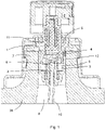
- Figures 1 to 4 show the operation of these pumps. Even though there exist a plurality of similar pump designs, with differences between one another, they all share elements which are essential for the invention, as indicated above. The remaining details are not relevant for the invention and can therefore be different from those shown in Figures 1 to 4 .
- the dispensing pump comprises:
- the piston 11 moves according to the axial direction between an expanded position (shown in Figure 1 ) and a retracted position (shown in Figure 3 ), going through a intermediate position (shown approximately in Figure 2 ), wherein when the piston 11 is in any position between the expanded position and the intermediate position, the side port 4 is arranged between the upper perimetral sealing lip 15 and the lower perimetral sealing lip 16, and when the piston 11 is in any position between the intermediate position and the retracted position, the side port 4 is arranged, in the axial direction, above the upper perimetral sealing lip 15.
- an air passage 22 suitable for establishing a fluidic communication between the exterior and the side port 4 when the piston 11 is in any position between the intermediate position and the retracted position.
- the evacuation means 17 are arranged in the upper portion of the piston 11, and comprise a cannula 23 (usually referred to as "stem"), a movable plug 24 and a head 25.
- the stem 23 is hollow and the lower portion thereof is located inside the piston 11 and the upper portion protrudes out of the piston 11.
- the head 25 is assembled on the upper portion of the stem 23.
- the hollow interior of the stem 23 establishes a fluidic passage between the pumping chamber 6 and the head 25, which in turn has a passage that allows the exit of the pumped liquid to the exterior, through the outlet port 18.
- the movable plug 24 is housed inside the stem 23.
- the lower end of the movable plug 24 protrudes below the stem 23 and is housed inside the piston 11.
- the lower end of the movable plug 24 has a perimetral edge suitable for being housed in a perimetral groove present in the piston 11, both elements thus forming the outlet valve 19.
- the pump is fixed to the container 26 by means of a fixing part 27 and a sleeve 28. These two elements form the fixing means and fix the pump body 1 to the neck 7 of the bottle in a leak-tight manner (thanks to a gasket 29) but allow the movement of the piston 11. More specifically, there is a passage between the piston 11 and the fixing part 27 which allows air to pass between the exterior and an intermediate chamber arranged between the upper portion of the pump body 1 and the piston 11, above the upper perimetral sealing lip 15. Therefore, when the dispensing pump is in its retracted position (see Figure 3 ), an air passage 22 communicating the interior of the container 26 with the exterior is established.
- This air passage 22 envisaged for allowing the entry of air in the container 26 and thus compensating for the vacuum formed by the liquid that is pumped, preventing a lower pressure being generated in the interior of the container 26.
- this air passage 22 is used to introduce the liquid from the cartridge 30 in the interior of the container 26, refilling it. It will also serve to allow the exit of air in the interior of the container 26 which, while refilling, is at an overpressure. Therefore, the air passage 22 transitions to having a triple function: allowing the entry of air during normal use of the pump, allowing the entry of liquid during the refilling method, and allowing the outlet of air during the refilling method.
- the dispensing pump described in the present figures is merely an example of among the existing plurality of pumps and there may be differences in detail between them. What is important for the present invention is that the mentioned air passage 22 (envisaged for allowing the entry of air to compensate for the exit of the pumped liquid) exists, since it is this air passage 22 that will be used by the invention for refilling the container 26.
- the container 26 is positioned in its normal position, i.e., with the bottom 61 in the lower position, such that the liquid in its inner volume 8 accumulates at the bottom 61 and the free end of the suction tube 10 is located below the free surface of the liquid, or at least, even in the event that it is above said free surface, it is so close that it will be immediately below said surface after having refilled a negligible amount of liquid.
- the head 25, which will be again placed at the end of the refilling process, will be extracted.
- connection means 31 are used.
- the connection means 31 have opening means 32 in the upper portion thereof for opening an outlet 33 arranged at the base 34 of the cartridge 30.
- the outlet 33 is a perforable film 35 and the opening means 32 comprise a needle 36 and a collapsible guard 37 of the needle 36.
- the connection means 31 have, in the lower portion thereof, a support surface 38, suitable for being supported on the stem 23 and pushing the piston 11 downwards, and a closure surface 39 suitable for being supported on the fixing part 27, forming a sealed closure, such that the air passage 22 is no longer in communication with the exterior but rather only with the interior of the cartridge 30.
- the piston 11 is moved to any position between the intermediate position (see Figure 2 ) and the retracted position (see Figure 3 ), i.e., to any position in which the side port 4 is arranged, in the axial direction, above the upper perimetral sealing lip 15 and, therefore, the air passage 22 is in fluidic communication with the inner volume 8 of the container 26.
- this step of moving the piston 11 is preferably done in parallel with the fluidic connection step for fluidically connecting the interior of the cartridge 30 with the air passage 22.
- the pressure is increased up to the pressure to which the liquid in the interior of the cartridge 30 is subjected, thereby causing the passage of part of the liquid to the inner volume 8, thereby increasing the pressure in the inner volume 8 (the air in the interior of the inner volume 8 cannot exit anywhere, since the suction tube 10 has its free end below the free surface of the liquid).
- air or any other gas
- air can be injected into the interior of the cartridge 30, for example, through the inlet valve 40 of the cartridge 30, as shown in Figure 7 .
- the upper portion of the cartridge 30 has a weakening area 65 demarcating a central area 66.
- This central area 66 has a perimeter equal to the inner surface of the side wall 41, such that it is suitable for being used as a piston running along the side wall 41.
- Figure 31 shows an external pushing member 67 (for example, that it is part of a machine according to the invention) which is pushing the central area 66, which increases the pressure in the liquid in the interior of the cartridge, such that it exits through the outlet 33.
- the method according to the invention contemplates a step in which the pressure to which the refilling liquid in the interior of the cartridge 30 is subjected is reduced to a value less than the pressure in the inner volume 8, thereby allowing part of the air under pressure in the inner volume 8 to pass into the interior of the cartridge 30 through the air passage 22 (see Figure 8 ). Then the cycle of injecting liquid and decompressing the container 26 is repeated a plurality of times until achieving the desired filled level, after which the cartridge 30 can be disconnected.
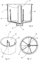
- FIGs 9 to 15 show a cartridge 30 according to the invention.
- the cartridge 30 has a main body ( Figures 9 to 11 ), with a side wall 41 and a base 34, and a lid ( Figures 12 to 14 ), which is assembled on the main body (see Figure 15 ), thus forming the upper portion 42 of the cartridge 30.
- the lid is welded to the side wall.
- the lid is formed as a single part with the side wall 41 and it is the base 34 that is configured as an independent part, attached (preferably by welding) to the side wall 41.
- the inlet valve 40 of the cartridge 30 (see Figures 12 to 14 , 17 , 19, and 20 ) comprises: [a] a conduit 43, defining a longitudinal axis, with a first segment 44 with a first triangular cross-section, a second segment 45 with a second cross-section circular, and a third segment 46 with a third cross-section which is also triangular and equal to the first cross-section, and [b] a spherical stopper 47 housed in the conduit 43.
- the diameter of the stopper 47 is greater than the diameter of the circle inscribed in the triangular cross-sections, such that the stopper is retained both in the first section and in the third section, except if a force greater than a predetermined value is applied thereto.
- the diameter of the stopper 47 is small enough so as to leave free passages at the vertexes of the triangles (see Figure 14 ). Therefore, when the stopper 47 is in the first segment 44 or in the third segment 46, the valve is open.
- the stopper 47 also has a diameter greater than the diameter of the circular cross-section, so the inlet valve 40 is closed when the stopper 47 is in the second segment 45.
- the cartridge 30 is manufactured with the stopper 47 in the first segment 44 (inlet valve 40 open, see Figure 19 ).
- the cartridge 30 can thereby be filled with liquid, after which the stopper 47 is pushed so as to move it towards the second segment 45, where the cartridge 30 is closed (see Figure 20 ).
- the stopper 47 is again pushed until it reaches the third segment 46, at which time the inlet valve 40 is open again (see Figure 17 ) and, for example, air (or any other gas) can be injected into the interior of the cartridge 30 for the purpose of increasing the pressure therein and forcing the exit of liquid through the outlet 33.
- the stopper 47 can be pushed by means of a rod 62, as shown in Figure 17 .
- the outlet 33 which, in the embodiment of Figures 9 to 11 , 15 , 16 , 18 , and 28-31 , is a perforable film 35.
- This perforable film 35 is what will be perforated by the needle 36 of the aforementioned connection means 31 (see Figures 6 to 8 and 18 ).
- the embodiment of Figure 21 shows an outlet 33 which is not a perforable film but rather comprises an outlet valve 48 similar to the inlet valve 40, although with only two segments.
- the outlet valve 48 comprises: [a] a conduit 143, defining a longitudinal axis, with a first segment 144 (the one oriented towards the interior of the cartridge 30) with a first triangular cross-section and a second segment 145 (the one oriented towards the exterior of the cartridge 30) with a second circular cross-section, and [b] a spherical stopper, housed in the conduit 143. Similar to the case of the inlet valve 40, when the stopper is in the first segment 144 the outlet valve 48 is open and when the stopper is in the second segment 145 the outlet valve 48 is closed. In the event that the cartridge 30 has an outlet valve 48 like the one described, the opening means will not have a needle but rather a rod 62 equivalent to the one shown in Figure 17 .
- the cartridge 30 comprises axial stiffening means 49 in the form of a hollow column 50 with a side opening 51.
- the column 50 extends from the base 34 to the upper portion 42, thus offering reinforcement with respect to stressing in the axial direction, particularly the stressing applied on the cartridge 30 during the refilling method.
- the hollow column 50 surrounds the edge of the outlet 33 of the cartridge 30.
- the side opening 51 the origin of which is at the base 34, allows the liquid contained in the cartridge 30 to flow in its entirety towards the outlet 33.
- the cartridge 30 also comprises radial stiffening means 52 in the form of ribs extending, on one hand, between said side wall 41 and said base 34 and, on the other, extending radially along said upper portion 42.
- Figure 22 shows a cartridge 30 with an individualized identifier 53.
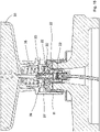
- Figures 23 to 26 show an embodiment of a machine according to the invention.
- the machine comprises a housing 54 suitable for housing the container 26 with the bottom 61 oriented downwards, connection means 31 suitable for connecting a cartridge 30 to the container 26, establishing a fluidic communication between the interior of the cartridge 30 and the air passage 22, pressurizing an depressurizing means 55 suitable for changing the pressure in the interior of the cartridge 30, and control means suitable for performing at least two pressurizing and depressurizing cycles, one after the other and automatically.
- the machine also comprises adjustment means 56 for adjusting the distance between the container 26 and the connection means 31.
- the pressurizing and depressurizing means 55 and the adjustment means 56 are a mechanism with several common elements: a servomotor 57 controls the movement of a piston 58 with its sleeve 63 along a vertical axis arranged on the housing 54. Under the sleeve 63 and attached to it there is a cartridge holder 59 suitable for supporting a cartridge 30. The connection means 31 are arranged between the cartridge 30 and the container 26. The activation of the servomotor 57 causes the movement of the piston + sleeve + cartridge holder assembly until the cartridge 30 is under pressure on the connection means 31 which are, in turn, on the dispensing pump. The assembly is thereby adjusted to the height of the container 26.
- the piston 58 which was fixed to the sleeve 63 at the beginning of its stroke, is released and starts to run along the sleeve 63, compressing the air in the interior thereof, which air will be injected into the interior of the cartridge 30.
- the piston 58 In a certain position, the piston 58 is stopped and the servomotor 57 moves it upwards. This causes the pressure to drop, allowing the exit of the air under pressure that is in the inner volume 8 of the container 26 towards the interior of the cartridge 30, as previously discussed.
- Figure 27 shows another embodiment of a machine according to the invention.
- the machine comprises a compressor 60 which generates the air under pressure that will be injected into the cartridge 30.
- a threading system 64 carries out the function of the adjustment means 56.
Abstract
Method for refilling a container (26) with a dispensing pump assembled on its neck (7), comprising the following steps:[1] positioning the container (26) upside right, and fluidically connecting the interior of a cartridge (30) with a refilling liquid with an air passage (22) present in the pump and that communicates the inner volume (8) of the container with the exterior in a specific position of the piston (11) of the pump,[2] moving the piston until a fluidic communication is established between the interior of the cartridge and the inner volume (8) through the air passage,[3] increasing the pressure to which the liquid in the interior of the cartridge is subjected, thereby causing the passage of part of the liquid to the inner volume, thereby increasing the pressure in the inner volume,[4] reducing the pressure in the interior of the cartridge to a value less than the pressure in the inner volume, thereby allowing air to pass from the inner volume to the interior of the cartridge through the air passage,[5] repeating steps [3] and [4] at least once,[6] disconnecting the cartridge.
Description
- The invention relates to a method for refilling a container, wherein the container has a neck, a bottom, and an inner volume, wherein the container has a dispensing pump assembled on the neck. Preferably the dispensing pump is assembled on the neck in an irreversible manner, i.e., in a manner that does not envisage the user disassembling it and assembling it again on the container. The dispensing pump comprises:
- [a] a pump body with:
- [a.1] a lower inlet port,
- [a.2] a cylindrical inner side surface defining an axial direction,
- [a.3] a side port arranged on the inner side surface, and
- [a.4] an upper opening,
- [b] an inlet valve arranged between the inlet port and the pumping chamber, suitable for allowing the entry of liquid in the interior of the pumping chamber through the inlet port and for blocking the exit of liquid in the interior of the pumping chamber through the inlet port,
- [c] a suction tube having one end connected to the inlet port and extending towards the bottom,
- [d] a piston with
- [d.1] a lower portion housed inside the pump body and comprising
- [d.1.1] an outer side surface, which is cylindrical according to the axial direction, facing the inner side surface, extending between an upper edge and a lower edge, wherein the side port is facing the outer side surface,
- [d.1.2] an upper perimetral sealing lip arranged in the upper portion of the outer side surface,
- [d.1.3] a lower perimetral sealing lip arranged in the lower portion of the outer side surface, and
- [d.2] an upper portion with evacuation means comprising an outlet port and an outlet valve, arranged between the outlet port and the pumping chamber, suitable for allowing the exit of liquid from the interior of the pumping chamber through the outlet port and for blocking the entry of air in the interior of the pumping chamber through the outlet port,
- [d.1] a lower portion housed inside the pump body and comprising
- [e] elastic means suitable for generating a force in the axial direction and prone to separating the piston from the pump body, and
- [f] fixing means for fixing the pump in the neck,
- In general, in the present description and claims, it should be understood that when reference is made to a cylindrical surface, this cylindrical surface is a cylindrical surface in the broadest sense, i.e., as any surface generated from the movement of a straight line along a generatrix curve. The particular case in which the cylindrical surface is a circular cylindrical surface (or a cylinder with a circular cross-section) is, however, a preferred option for the present invention.
- Another object of the invention is a cartridge suitable for housing a liquid in the interior thereof, comprising a side wall, a base, and an upper portion. The cartridge according to the invention can be empty of liquid (for example, before being filled) or full of liquid.
- Another object of the invention is a management system of a cartridge according to the invention.
- Finally, another object of the invention is a machine for performing a method according to the invention.
- Containers (for example bottles) with a dispensing pump assembled on the neck thereof are commonly used in a plurality of applications. In particular, containers with a dispensing pump such as the one indicated above are widely known. A common use is for the metering of perfumery, cosmetic, hygiene, and similar products. In specific cases, it is envisaged that the user can unscrew the dispensing pump from the neck of the container and can refill the container. However, in a plurality of cases a refilling of the containers is not envisaged, said containers therefore being conceived as single-use containers. That is particularly the case when the dispensing pump is assembled on the container in a non-removable manner.
- It is of interest to offer solutions which allow the refilling of these containers, among others, to prevent the negative ecological impact caused by empty containers, as well as all the accessories used in their decoration, and the actual process of manufacturing same.
-
US 10 399 103 B2 -
US 9 834 369 B2 - It is an object of the invention to offer a system which allows the refilling of containers (preferably bottles) which have a dispensing pump assembled thereon. This purpose is achieved by a method of the type indicated above, characterized in that it comprises the following steps:
- [1] positioning the container such that the bottom is in the lower position, and fluidically connecting the interior of a cartridge comprising a refilling liquid with the air passage,
- [2] moving the piston to any position between the intermediate position and the retracted position, thereby establishing a fluidic communication between the interior of the cartridge and the inner volume,
- [3] increasing the pressure to which the refilling liquid in the interior of the cartridge is subjected, thereby causing the passage of part of the liquid to the inner volume, thereby increasing the pressure in the inner volume,
- [4] reducing the pressure to which the refilling liquid in the interior of the cartridge is subjected to a value less than the pressure in the inner volume, thereby allowing part of the air under pressure in the inner volume to pass to the interior of the cartridge through the air passage,
- [5] repeating steps [3] and [4] at least once,
- [6] disconnecting the cartridge.
- The method according to the invention thus uses the air passage existing in the pump both for introducing the liquid in the container and for extracting the air accumulated in the interior of the container. During step [3], the liquid gradually fills the inner volume of the container, but the air in the inner volume of the container cannot exit anywhere because, since the container is "right-side up", i.e., with the bottom in the lower position, the free end of the suction tube is below the free surface of the liquid. Therefore, the pressure in the interior of the container gradually increases and, accordingly, it is also necessary to increase the pressure to which the liquid in the interior of the cartridge is subjected for it to continue flowing towards the inner volume of the container. To prevent the pressure from increasing to unwanted values, the filling of the container is interrupted by reducing the pressure in the interior of the cartridge to a value less than the pressure in the interior of the container. The air in the interior of the container can then pass through the air passage towards the interior of the cartridge, thus lowering the pressure in the interior of the container to a desired value. The steps of increasing the pressure in the interior of the cartridge and of reducing the pressure are then repeated a plurality of times until reaching the desired filled level.
- It should be taken into account that the indicated steps do not necessarily have to all be performed in the indicated sequence, but rather other sequences are also possible. For example, steps [1] and [2] and/or at least part of the sub-steps they comprise (positioning the container such that the bottom is in the lower position, fluidically connecting the interior of a cartridge comprising a refilling liquid with the air passage, moving the piston to any position between the intermediate position and the retracted position) can be satisfactorily performed in several different sequences and/or some of them can be performed simultaneously. Therefore, the indicated order is not a rigid definition of the sequence in which the steps and sub-steps take place, but rather is a mere indication of the steps comprised in the method according to the invention.
- Preferably in step [3], the pressure is increased between 0.5 and 2 bar above atmospheric pressure. This pressure is high enough so as to allow a refilling with a smaller number of steps but without subjecting the container to such a high excess pressure that may cause said container to break.
- Advantageously, steps [3] and [4] are performed between 2 and 4 times, and preferably between 3 and 4 times.
- Preferably, the cartridge comprises an individualized identifier for each cartridge and the method comprises a verification step by a user to verify the individualized identifier of the full cartridge, this verification step being performed prior to fluidically connecting the interior of the cartridge comprising a refilling liquid with the air passage. An advantageous alternative is presented when the method is performed by means of a machine comprising a reader of the individualized identifier and communication means suitable for establishing communication with a verifying entity of the individualized identifier (and, advantageously, also with other external databases), and the verification step is performed automatically by the machine, in which case the following is particularly advantageous: [a] if said verification gives a positive result, the machine continues with the refilling method and disables the individualized identifier (notifying the verifying entity that it has been used), and/or [b] if the verification gives a negative result, the machine interrupts the refilling method. Another advantageous alternative is presented when the verification step is performed by the user with other means, preferably by means of a mobile telephone.
- Preferably the inlet valve is a ball valve.
- Another object of the invention is a cartridge of the type indicated above, characterized in that it comprises an inlet with an inlet valve arranged in said upper portion and an outlet arranged on said base.
- Preferably, the inlet valve is a three-position valve, and very preferably comprises: [a] a conduit, defining a longitudinal axis, with a first segment with a first cross-section, a second segment with a second cross-section different from the first cross-section, and a third segment with a third cross-section different from the second cross-section, and [b] a stopper, housed in the conduit, with a cross-section such that when the stopper is in the first segment or in the third segment the valve is open and when the stopper is in the second segment the valve is closed. Advantageously, the first cross-section and the third cross-section are polygonal and the stopper has a circular cross-section, the circular cross-section being of a diameter greater than the diameter of a circle inscribed in any of the polygonal cross-sections, and it is particularly advantageous for the first cross-section and the third cross-section to be triangular. In turn, it is advantageous for the second cross-section to be circular and for the stopper to also have a circular cross-section, the circular cross-section of the stopper being of a diameter greater than the diameter of the second cross-section. An inlet valve of this type is inexpensive to manufacture and can be made entirely of one and the same material. It is very simple for the valve to pass from the open position to the closed position and, subsequently, to the open position again.
- Preferably, the stopper of the inlet valve is spherical.
- Advantageously, the outlet comprises a perforable film. In an alternative advantageous solution, the outlet comprises an outlet valve comprising: [a] a conduit, defining a longitudinal axis, with a first segment with a first cross-section and a second segment with a second cross-section different from the first cross-section, wherein the first segment is oriented towards the interior of the cartridge and the second segment is oriented towards the exterior of the cartridge, and [b] a stopper, housed in the conduit, with a cross-section such that when the stopper is in the first segment the valve is open and when the stopper is in the second segment the valve is closed. In this alternative, it is advantageous for the first cross-section to be polygonal and for the stopper to have a circular cross-section, the circular cross-section being of a diameter greater than the diameter of a circle inscribed in the polygonal cross-section, and it is particularly advantageous for the first cross-section to be triangular. In this alternative, it is also advantageous for the second cross-section to be circular and for the stopper to also have a circular cross-section, the circular cross-section of the stopper being of a diameter greater than the diameter of the second cross-section.
- Preferably, the stopper of the outlet valve is spherical.
- In an advantageous embodiment of a cartridge according to the invention, the upper portion has a weakening area demarcating a central area, wherein the weakening area has a shape such that the central area has a perimeter equal to the inner surface of the side wall, such that the central area is suitable for being used as a piston running along the side wall. Cartridges of this type can thereby be used with machines having a pushing member which pushes the central area, tearing the upper portion in the weakening area, and then pushing the liquid out through the outlet. As will be seen below, another preferred embodiment consists of injecting air (or any gas in general) into the interior of the cartridge.
- Preferably, the cartridge comprises axial stiffening means. Preferably, these axial stiffening means comprise a hollow column, with a side opening, wherein the column extends from the base to the upper portion, and the hollow column is advantageously attached to the upper portion.
- Preferably, the cartridge comprises radial stiffening means. Advantageously, these radial stiffening means comprise a plurality of ribs extending between the side wall and the base and/or comprise a plurality of ribs extending radially along the upper portion.
- Indeed, these cartridges are subjected to high pressures, so they must also be kept with a high pressure. All this makes it convenient to reinforce the cartridge both in an axial direction, to prevent deformations when being secured by the machine, and in a radial direction, to prevent deformations due to high internal pressure during the process of refilling the container.
- Preferably, the base and the side wall are a single part and the upper portion is an independent part assembled on the side wall. The manufacturing process is thereby optimized, reducing costs.
- Advantageously, the cartridge is made entirely of one and the same polymer material. The assembly can thereby be recycled without the need to perform separation processes.
- Preferably, the cartridge comprises an individualized identifier for each cartridge. The individualized identifier is advantageously a barcode, preferably a matrix barcode and very preferably a QR code.
- Another object of the invention is a management system for managing a cartridge comprising an individualized identifier according to the invention, characterized in that it comprises the following steps:
- [a] assigning a specific individualized identifier to a specific cartridge during the manufacture of the cartridge and marking the cartridge with the individualized identifier,
- [b] validating the individualized identifier during the filling process of the cartridge,
- [c] verifying the individualized identifier of the full cartridge by a user, and, preferably, marking the individualized identifier after being used in a refilling method, and disabling the individualized identifier for future uses.
- Preferably, the system includes an additional step in which, after the disabling step for disabling the identifier, the appropriate person is informed of the disabling step performed, preferably including information about the type of cartridge, the date on which and location where disabling has taken place.
- Finally, another object of the invention is a machine for performing a method according to the invention, characterized in that it comprises:
- a housing suitable for housing the container with the bottom oriented downwards,
- connection means suitable for connecting a cartridge according to the invention to the bottle, establishing a fluidic communication between the interior of the cartridge and the air passage,
- pressurizing means suitable for increasing the pressure in the interior of the cartridge above atmospheric pressure,
- depressurizing means suitable for reducing the pressure in the interior of the cartridge,
- control means suitable for performing at least two pressurizing and depressurizing cycles one after the other and automatically.
- Preferably, the machine comprises adjustment means for adjusting the distance between the container and the connection means. Given that there is a plurality of container and dispensing pump designs on the market which have different heights, the presence of the adjustment means allows the machine to be used for a plurality of different designs.
- Advantageously, the connection means are removable. In general, it is of interest the machine to be compatible with a plurality of containers that are different from one another, which will have dispensing pumps different from one another. Indeed, although the dispensing pumps must always have the same elements required for the invention, they may vary in regard to other elements that are not indispensable for the invention. However, these differences may require the connection means to be different in the support area with the pump (diameters, heights) depending on the pump in question. It may also be appropriate for the connection means to be compatible with different families of cartridges. Being able to provide a family of connection means and being able to use one or the other, depending on the container (with the corresponding pump) to be refilled, is therefore of interest.
- Preferably, the connection means comprise, in the upper portion thereof, opening means of an outlet arranged at the base of the cartridge. In a preferred embodiment, the opening means comprise a needle, and very preferably a collapsible guard of the needle. In another preferred embodiment, the opening means comprise a rod suitable for pushing a stopper housed in a conduit arranged in the outlet of the cartridge.
- Advantageously, the connection means comprise, in the lower portion thereof, a support surface suitable for moving the piston and a closure surface suitable for being supported on the pump and forming a sealed closure between the air passage and the exterior, such that the air passage only in fluidic communication with the interior of the cartridge.
- Preferably, the machine comprises a reader for reading the individualized identifier and communication means suitable for establishing communication with a verifying entity of the individualized identifier.
- Further advantages and features of the invention will become apparent from the following description, in which, without any limiting character, preferred embodiments of the invention are disclosed, with reference to the accompanying figures. In the figures:
-
Figures 1 to 4 show a longitudinal section of a dispensing pump in four positions of the pumping cycle. -
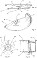
Figures 5 to 8 show a sequence of the steps of the method according to the invention. -
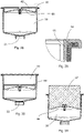
Figures 9 to 11 show a longitudinal section, a perspective view, and a top plan view of a main body of a first embodiment of a cartridge according to the invention. -
Figures 12 to 14 show a longitudinal section, a sectioned perspective view, and a detail of a top plan view of a lid of a cartridge according to the invention. -
Figure 15 shows a partially sectioned elevation view of the assembly formed by the main body ofFigures 9 to 11 and the lid ofFigures 12 to 14 . -
Figure 16 shows an enlarged view of the connection means ofFigure 8 . -
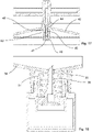
Figure 17 shows a longitudinal section of an inlet valve of a capsule according to the invention, with a rod pushing the stopper. -
Figure 18 shows a longitudinal section of the connection means connected to a capsule. -
Figures 19 and 20 show a longitudinal section of an inlet valve of a capsule with the stopper in two positions. -
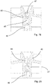
Figure 21 shows a longitudinal section of a main body of a second embodiment of a cartridge according to the invention. -
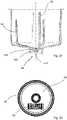
Figure 22 shows a bottom plan view of a cartridge with an individualized identifier. -
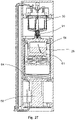
Figures 23 to 26 show a first embodiment of a machine according to the invention. -
Figure 27 shows a second embodiment of a machine according to the invention. -
Figure 28 shows a longitudinal section of another embodiment of a cartridge according to the invention. -
Figure 29 shows an enlarged view of the area of attachment of the upper portion and the side wall of the cartridge ofFigure 28 . -
Figure 30 shows a longitudinal section of the cartridge ofFigure 28 , with the central area of the upper portion in an intermediate position with respect to the side wall. -
Figure 31 shows a view equivalent to the view ofFigure 30 , but including an external pushing member moving the central area. - In general, the method according to the invention is performed for refilling containers having a specific type of dispensing pumps, as indicated above.
Figures 1 to 4 show the operation of these pumps. Even though there exist a plurality of similar pump designs, with differences between one another, they all share elements which are essential for the invention, as indicated above. The remaining details are not relevant for the invention and can therefore be different from those shown inFigures 1 to 4 . The dispensing pump comprises: - [a] a
pump body 1 with:- [a.1] a
lower inlet port 2, - [a.2] a cylindrical
inner side surface 3 defining an axial direction, - [a.3] a
side port 4 arranged on theinner side surface 3, and - [a.4] an
upper opening 5,
pump body 1 defines apumping chamber 6 in the interior thereof, wherein when the pump is in an assembled position, the upper opening protrudes from theneck 7 of thecontainer 26 on which the pump is assembled and thelower inlet port 2 is inside thecontainer 26, and theside port 4 communicates theinner side surface 3 with theinner volume 8 of thecontainer 26, - [a.1] a
- [b] an inlet valve 9 (which is preferably a ball valve, regardless of the remaining elements described in this pump) arranged between the
inlet port 2 and thepumping chamber 6, suitable for allowing the entry of liquid in the interior of thepumping chamber 6 through theinlet port 2 and for blocking the exit of liquid in the interior of thepumping chamber 6 through theinlet port 2, - [c] a
suction tube 10 having one end connected to theinlet port 2 and extending towards the bottom 61 of thecontainer 26, - [d] a
piston 11 with:- [d.1] a lower portion housed inside the
pump body 1 and comprising:- [d.1.1] an
outer side surface 12, which is cylindrical according to the axial direction, facing theinner side surface 3, extending between anupper edge 13 and alower edge 14, wherein theside port 4 is facing theouter side surface 12, - [d.1.2] an upper
perimetral sealing lip 15 arranged in the upper portion of theouter side surface 12, - [d.1.3] a lower
perimetral sealing lip 16 arranged in the lower portion of theouter side surface 12, and
- [d.1.1] an
- [d.2] an upper portion with evacuation means 17 (an assembly of elements of the pump corresponding with everything that is related to the exit of the liquid from the
pumping chamber 6 to the exterior is referred to as "evacuation means") comprising anoutlet port 18 and anoutlet valve 19, arranged between theoutlet port 18 and thepumping chamber 6, suitable for allowing the exit of liquid from the interior of thepumping chamber 6 through theoutlet port 18 and for blocking the entry of air in the interior of thepumping chamber 6 through theoutlet port 18,
- [d.1] a lower portion housed inside the
- [e] elastic means 20 suitable for generating a force in the axial direction and prone to separating the piston from the
pump body 1, and - [f] fixing means for fixing the pump in the
neck 7. - During a movement of actuation of the pump, the
piston 11 moves according to the axial direction between an expanded position (shown inFigure 1 ) and a retracted position (shown inFigure 3 ), going through a intermediate position (shown approximately inFigure 2 ), wherein when thepiston 11 is in any position between the expanded position and the intermediate position, theside port 4 is arranged between the upperperimetral sealing lip 15 and the lowerperimetral sealing lip 16, and when thepiston 11 is in any position between the intermediate position and the retracted position, theside port 4 is arranged, in the axial direction, above the upperperimetral sealing lip 15. Between thepiston 11, thepump body 1, and the fixing means there is anair passage 22 suitable for establishing a fluidic communication between the exterior and theside port 4 when thepiston 11 is in any position between the intermediate position and the retracted position. - The evacuation means 17 are arranged in the upper portion of the
piston 11, and comprise a cannula 23 (usually referred to as "stem"), amovable plug 24 and ahead 25. Thestem 23 is hollow and the lower portion thereof is located inside thepiston 11 and the upper portion protrudes out of thepiston 11. Thehead 25 is assembled on the upper portion of thestem 23. The hollow interior of thestem 23 establishes a fluidic passage between the pumpingchamber 6 and thehead 25, which in turn has a passage that allows the exit of the pumped liquid to the exterior, through theoutlet port 18. Themovable plug 24 is housed inside thestem 23. The lower end of themovable plug 24 protrudes below thestem 23 and is housed inside thepiston 11. The lower end of themovable plug 24 has a perimetral edge suitable for being housed in a perimetral groove present in thepiston 11, both elements thus forming theoutlet valve 19. - The pump is fixed to the
container 26 by means of a fixingpart 27 and asleeve 28. These two elements form the fixing means and fix thepump body 1 to theneck 7 of the bottle in a leak-tight manner (thanks to a gasket 29) but allow the movement of thepiston 11. More specifically, there is a passage between thepiston 11 and the fixingpart 27 which allows air to pass between the exterior and an intermediate chamber arranged between the upper portion of thepump body 1 and thepiston 11, above the upperperimetral sealing lip 15. Therefore, when the dispensing pump is in its retracted position (seeFigure 3 ), anair passage 22 communicating the interior of thecontainer 26 with the exterior is established. These dispensing pumps have thisair passage 22 envisaged for allowing the entry of air in thecontainer 26 and thus compensating for the vacuum formed by the liquid that is pumped, preventing a lower pressure being generated in the interior of thecontainer 26. However, as discussed in detail below, in the present invention thisair passage 22 is used to introduce the liquid from thecartridge 30 in the interior of thecontainer 26, refilling it. It will also serve to allow the exit of air in the interior of thecontainer 26 which, while refilling, is at an overpressure. Therefore, theair passage 22 transitions to having a triple function: allowing the entry of air during normal use of the pump, allowing the entry of liquid during the refilling method, and allowing the outlet of air during the refilling method. As previously indicated, the dispensing pump described in the present figures is merely an example of among the existing plurality of pumps and there may be differences in detail between them. What is important for the present invention is that the mentioned air passage 22 (envisaged for allowing the entry of air to compensate for the exit of the pumped liquid) exists, since it is thisair passage 22 that will be used by the invention for refilling thecontainer 26. - A sequence of the steps of the method according to the invention can be observed in
Figures 5 to 8 . - First, the
container 26 is positioned in its normal position, i.e., with the bottom 61 in the lower position, such that the liquid in itsinner volume 8 accumulates at the bottom 61 and the free end of thesuction tube 10 is located below the free surface of the liquid, or at least, even in the event that it is above said free surface, it is so close that it will be immediately below said surface after having refilled a negligible amount of liquid. Thehead 25, which will be again placed at the end of the refilling process, will be extracted. - The interior of a
cartridge 30 comprising the refilling liquid is fluidically connected with theair passage 22. To that end, connection means 31 are used. The connection means 31 have opening means 32 in the upper portion thereof for opening anoutlet 33 arranged at thebase 34 of thecartridge 30. In the example ofFigures 5 to 8 , theoutlet 33 is aperforable film 35 and the opening means 32 comprise aneedle 36 and acollapsible guard 37 of theneedle 36. The connection means 31 have, in the lower portion thereof, asupport surface 38, suitable for being supported on thestem 23 and pushing thepiston 11 downwards, and aclosure surface 39 suitable for being supported on the fixingpart 27, forming a sealed closure, such that theair passage 22 is no longer in communication with the exterior but rather only with the interior of thecartridge 30. - The
piston 11 is moved to any position between the intermediate position (seeFigure 2 ) and the retracted position (seeFigure 3 ), i.e., to any position in which theside port 4 is arranged, in the axial direction, above the upperperimetral sealing lip 15 and, therefore, theair passage 22 is in fluidic communication with theinner volume 8 of thecontainer 26. As previously discussed, there are several steps of the method according to the invention which can be performed in sequences different from those written. Thus, for example, this step of moving thepiston 11 is preferably done in parallel with the fluidic connection step for fluidically connecting the interior of thecartridge 30 with theair passage 22. - Once the fluidic connections have been established (see
Figures 6 and16 ) the pressure is increased up to the pressure to which the liquid in the interior of thecartridge 30 is subjected, thereby causing the passage of part of the liquid to theinner volume 8, thereby increasing the pressure in the inner volume 8 (the air in the interior of theinner volume 8 cannot exit anywhere, since thesuction tube 10 has its free end below the free surface of the liquid). For increasing the pressure to which the liquid in the interior of thecartridge 30 is subjected, air (or any other gas) can be injected into the interior of thecartridge 30, for example, through theinlet valve 40 of thecartridge 30, as shown inFigure 7 . However, other solutions are also possible, such as conceiving the upper portion of thecartridge 30 as a plunger which can be moved (seeFigures 28 to 31 ). In the cartridge shown inFigures 28 to 31 , theupper portion 42 has a weakeningarea 65 demarcating acentral area 66. Thiscentral area 66 has a perimeter equal to the inner surface of theside wall 41, such that it is suitable for being used as a piston running along theside wall 41.Figure 31 shows an external pushing member 67 (for example, that it is part of a machine according to the invention) which is pushing thecentral area 66, which increases the pressure in the liquid in the interior of the cartridge, such that it exits through theoutlet 33. - If the
container 26 is refilled with a single injection of liquid, the volume of air that was initially in thecontainer 26 is compressed to a very small volume, which greatly increases the pressure in the interior of thecontainer 26. To prevent these high increases in pressure for which the container has not been designed, the method according to the invention contemplates a step in which the pressure to which the refilling liquid in the interior of thecartridge 30 is subjected is reduced to a value less than the pressure in theinner volume 8, thereby allowing part of the air under pressure in theinner volume 8 to pass into the interior of thecartridge 30 through the air passage 22 (seeFigure 8 ). Then the cycle of injecting liquid and decompressing thecontainer 26 is repeated a plurality of times until achieving the desired filled level, after which thecartridge 30 can be disconnected. -
Figures 9 to 15 show acartridge 30 according to the invention. Thecartridge 30 has a main body (Figures 9 to 11 ), with aside wall 41 and abase 34, and a lid (Figures 12 to 14 ), which is assembled on the main body (seeFigure 15 ), thus forming theupper portion 42 of thecartridge 30. Preferably, the lid is welded to the side wall. In another advantageous embodiment of a cartridge according to the invention, the lid is formed as a single part with theside wall 41 and it is the base 34 that is configured as an independent part, attached (preferably by welding) to theside wall 41. - In the lid of the
cartridge 30 there is an inlet with aninlet valve 40. Theinlet valve 40 of the cartridge 30 (seeFigures 12 to 14 ,17 ,19, and 20 ) comprises: [a] aconduit 43, defining a longitudinal axis, with afirst segment 44 with a first triangular cross-section, asecond segment 45 with a second cross-section circular, and athird segment 46 with a third cross-section which is also triangular and equal to the first cross-section, and [b] aspherical stopper 47 housed in theconduit 43. The diameter of thestopper 47 is greater than the diameter of the circle inscribed in the triangular cross-sections, such that the stopper is retained both in the first section and in the third section, except if a force greater than a predetermined value is applied thereto. However, the diameter of thestopper 47 is small enough so as to leave free passages at the vertexes of the triangles (seeFigure 14 ). Therefore, when thestopper 47 is in thefirst segment 44 or in thethird segment 46, the valve is open. Thestopper 47 also has a diameter greater than the diameter of the circular cross-section, so theinlet valve 40 is closed when thestopper 47 is in thesecond segment 45. Thus, thecartridge 30 is manufactured with thestopper 47 in the first segment 44 (inlet valve 40 open, seeFigure 19 ). Thecartridge 30 can thereby be filled with liquid, after which thestopper 47 is pushed so as to move it towards thesecond segment 45, where thecartridge 30 is closed (seeFigure 20 ). When acontainer 26 is to be refilled with the liquid of thecartridge 30, thestopper 47 is again pushed until it reaches thethird segment 46, at which time theinlet valve 40 is open again (seeFigure 17 ) and, for example, air (or any other gas) can be injected into the interior of thecartridge 30 for the purpose of increasing the pressure therein and forcing the exit of liquid through theoutlet 33. Thestopper 47 can be pushed by means of arod 62, as shown inFigure 17 . - At the
base 34 of thecartridge 30 is theoutlet 33 which, in the embodiment ofFigures 9 to 11 ,15 ,16 ,18 , and28-31 , is aperforable film 35. Thisperforable film 35 is what will be perforated by theneedle 36 of the aforementioned connection means 31 (seeFigures 6 to 8 and18 ). The embodiment ofFigure 21 shows anoutlet 33 which is not a perforable film but rather comprises anoutlet valve 48 similar to theinlet valve 40, although with only two segments. Namely, theoutlet valve 48 comprises: [a] aconduit 143, defining a longitudinal axis, with a first segment 144 (the one oriented towards the interior of the cartridge 30) with a first triangular cross-section and a second segment 145 (the one oriented towards the exterior of the cartridge 30) with a second circular cross-section, and [b] a spherical stopper, housed in theconduit 143. Similar to the case of theinlet valve 40, when the stopper is in thefirst segment 144 theoutlet valve 48 is open and when the stopper is in thesecond segment 145 theoutlet valve 48 is closed. In the event that thecartridge 30 has anoutlet valve 48 like the one described, the opening means will not have a needle but rather arod 62 equivalent to the one shown inFigure 17 . - The
cartridge 30 comprises axial stiffening means 49 in the form of ahollow column 50 with aside opening 51. Thecolumn 50 extends from the base 34 to theupper portion 42, thus offering reinforcement with respect to stressing in the axial direction, particularly the stressing applied on thecartridge 30 during the refilling method. Preferably, thehollow column 50 surrounds the edge of theoutlet 33 of thecartridge 30. Theside opening 51, the origin of which is at thebase 34, allows the liquid contained in thecartridge 30 to flow in its entirety towards theoutlet 33. - The
cartridge 30 also comprises radial stiffening means 52 in the form of ribs extending, on one hand, between saidside wall 41 and saidbase 34 and, on the other, extending radially along saidupper portion 42. -
Figure 22 shows acartridge 30 with anindividualized identifier 53. -
Figures 23 to 26 show an embodiment of a machine according to the invention. The machine comprises ahousing 54 suitable for housing thecontainer 26 with the bottom 61 oriented downwards, connection means 31 suitable for connecting acartridge 30 to thecontainer 26, establishing a fluidic communication between the interior of thecartridge 30 and theair passage 22, pressurizing an depressurizing means 55 suitable for changing the pressure in the interior of thecartridge 30, and control means suitable for performing at least two pressurizing and depressurizing cycles, one after the other and automatically. The machine also comprises adjustment means 56 for adjusting the distance between thecontainer 26 and the connection means 31. In fact, the pressurizing and depressurizing means 55 and the adjustment means 56 are a mechanism with several common elements: aservomotor 57 controls the movement of apiston 58 with itssleeve 63 along a vertical axis arranged on thehousing 54. Under thesleeve 63 and attached to it there is acartridge holder 59 suitable for supporting acartridge 30. The connection means 31 are arranged between thecartridge 30 and thecontainer 26. The activation of theservomotor 57 causes the movement of the piston + sleeve + cartridge holder assembly until thecartridge 30 is under pressure on the connection means 31 which are, in turn, on the dispensing pump. The assembly is thereby adjusted to the height of thecontainer 26. After this point thepiston 58, which was fixed to thesleeve 63 at the beginning of its stroke, is released and starts to run along thesleeve 63, compressing the air in the interior thereof, which air will be injected into the interior of thecartridge 30. In a certain position, thepiston 58 is stopped and theservomotor 57 moves it upwards. This causes the pressure to drop, allowing the exit of the air under pressure that is in theinner volume 8 of thecontainer 26 towards the interior of thecartridge 30, as previously discussed. -
Figure 27 shows another embodiment of a machine according to the invention. In this case, the machine comprises acompressor 60 which generates the air under pressure that will be injected into thecartridge 30. In turn, athreading system 64 carries out the function of the adjustment means 56.
wherein between the piston, the pump body, and the fixing means there is an air passage suitable for establishing a fluidic communication between the exterior and the side port when the piston is in any position between the intermediate position and the retracted position.
Claims (16)
- Method for refilling a container (26), wherein said container (26) has a neck (7), a bottom (61), and an inner volume (8), wherein said container (26) has a dispensing pump assembled on said neck (7), wherein said pump comprises:[a] a pump body (1) with:[a.1] a lower inlet port (2),[a.2] a cylindrical inner side surface (3) defining an axial direction,[a.3] a side port (4) arranged on said inner side surface (3), and[a.4] an upper opening (5),wherein the pump body (1) defines a pumping chamber (6) in the interior thereof, wherein when the pump is in an assembled position, said upper opening protrudes from said neck (7) and said lower inlet port (2) is inside said container (26), and said side port (4) communicates said inner side surface (3) with said inner volume (8),[b] an inlet valve (9) arranged between said lower inlet port (2) and said pumping chamber (6), suitable for allowing the entry of liquid in the interior of said pumping chamber (6) through said lower inlet port (2) and for blocking the exit of liquid in the interior of said pumping chamber (6) through said lower inlet port (2),[c] a suction tube (10) having one end connected to said lower inlet port (2) and extending towards said bottom (61),[d] a piston (11) with[d.1] a lower portion housed inside said pump body (1) and comprising[d.1.1] an outer side surface (12), which is cylindrical according to said axial direction, facing said inner side surface (3), extending between an upper edge (13) and a lower edge (14), wherein said side port (4) is facing said outer side surface (12)[d.1.2] an upper perimetral sealing lip (15) arranged in the upper portion of said outer side surface (12),[d.1.3] a lower perimetral sealing lip (16) arranged in the lower portion of said outer side surface (12),[d.2] and an upper portion with evacuation means (17) comprising an outlet port (18) and an outlet valve (19), arranged between said outlet port (18) and said pumping chamber (6), suitable for allowing the exit of liquid from the interior of said pumping chamber (6) through said outlet port (18) and for blocking the entry of air in the interior of said pumping chamber (6) through said outlet port (18),[e] elastic means (20) suitable for generating a force in said axial direction and prone to separating said piston (11) from said pump body (1), and[f] fixing means for fixing said pump in said neck (7),wherein, during a movement of actuation of said pump, said piston (11) moves according to said axial direction between an expanded position and a retracted position, going through an intermediate position, wherein when said piston (11) is in any position between said expanded position and said intermediate position, said side port (4) is arranged between said upper perimetral sealing lip (15) and said lower perimetral sealing lip (16), and when said piston (11) is in any position between said intermediate position and said retracted position, said side port (4) is arranged, in said axial direction, above said upper perimetral sealing lip (15),
wherein between said piston (11), said pump body (1), and said fixing means there is an air passage (22) suitable for establishing a fluidic communication between the exterior and said side port (4) when said piston (11) is in any position between said intermediate position and said retracted position,
characterized in that it comprises the following steps:[1] positioning said container (26) such that said bottom (61) is in the lower position, and fluidically connecting the interior of a cartridge (30) comprising a refilling liquid with said air passage (22),[2] moving said piston (11) to any position between said intermediate position and said retracted position, thereby establishing a fluidic communication between said interior of said cartridge (30) and said inner volume (8),[3] increasing the pressure to which said refilling liquid in said interior of the cartridge (30) is subjected, thereby causing the passage of part of said liquid to said inner volume (8), thereby increasing the pressure in said inner volume (8),[4] reducing the pressure to which said refilling liquid in said interior of the cartridge (30) is subjected to a value less than the pressure in said inner volume (8), thereby allowing part of the air under pressure in said inner volume (8) to pass to said interior of the cartridge (30) through said air passage (22),[5] repeating steps [3] and [4] at least once,[6] disconnecting said cartridge (30). - The method according to claim 1, characterized in that said cartridge (30) comprises an individualized identifier (53) for each cartridge (30), and in that said method comprises a verification step by a user to verify said individualized identifier (53) of said full cartridge (30), which is performed prior to fluidically connecting the interior of said cartridge (30) comprising a refilling liquid with said air passage (22).
- The method according to claim 2, characterized in that said method is performed by means of a machine comprising a reader of said individualized identifier (53) and communication means suitable for establishing communication with a verifying entity of said individualized identifier (53), and said verification step is performed automatically by said machine.
- A cartridge (30) suitable for housing a liquid in the interior thereof, comprising a side wall (41), a base (34), and an upper portion (42), characterized in that it comprises an inlet with an inlet valve (40) arranged in said upper portion (42) and an outlet (33) arranged on said base (34).
- The cartridge (30) according to claim 4, characterized in that said inlet valve (40) comprises: [a] a conduit (43), defining a longitudinal axis, with a first segment (44) with a first cross-section, a second segment (45) with a second cross-section different from said first cross-section, and a third segment (46) with a third cross-section different from said second cross-section, and [b] a stopper (47), housed in said conduit (43), with a cross-section such that when said stopper (47) is in said first segment (44) or in said third segment (46) said valve is open and when said stopper (47) is in said second segment (45) said valve is closed.
- The cartridge (30) according to one of claims 4 or 5, characterized in that said outlet (33) comprises a perforable film (35).
- The cartridge (30) according to one of claims 4 or 5, characterized in that said outlet (33) comprises an outlet valve (48) comprising: [a] a conduit (143), defining a longitudinal axis, with a first segment (144) with a first cross-section and a second segment (145) with a second cross-section different from said first cross-section, wherein said first segment (144) is oriented towards the interior of said cartridge (30) and said second segment (145) is oriented towards the exterior of said cartridge (30), and [b] a stopper, housed in said conduit (143), with a cross-section such that when said stopper is in said first segment (144) said valve is open and when said stopper is in said second segment (145) said valve is closed.
- The cartridge (30) according to any one of claims 4 to 7, characterized in that it comprises axial stiffening means (49), wherein said axial stiffening means (49) preferably comprise a hollow column (50), with a side opening (51), said column (50) extending from said base (34) to said upper portion (42).
- The cartridge (30) according to any one of claims 4 to 8, characterized in that it comprises radial stiffening means (52), wherein said radial stiffening means (52) preferably comprise a plurality of ribs extending between said side wall (41) and said base (34) and/or comprise a plurality of ribs extending radially along said upper portion (42).
- The cartridge (30) according to any one of claims 4 to 9, characterized in that it comprises an individualized identifier (53) for each cartridge (30), wherein said identifier is preferably a barcode and is very preferably a QR code.
- The cartridge according to any one of claims 4 to 10, characterized in that said upper portion (42) has a weakening area (65) demarcating a central area (66), said central area (66) having a perimeter equal to the inner surface of said side wall (41) and being suitable for being used as a piston running along said side wall (41).
- A management system for managing a cartridge (30) according to claim 10, characterized in that it comprises the following steps:[a] assigning a specific individualized identifier (53) to a specific cartridge (30) during the manufacture of said cartridge (30) and marking said cartridge (30) with said individualized identifier (53),[b] validating said individualized identifier (53) during the filling process of said cartridge (30),[c] verifying said individualized identifier (53) of said full cartridge (30) by a user, and, preferably, marking said individualized identifier (53) after being used in a refilling method, and disabling said individualized identifier (53) for future uses.
- Machine for performing a method according to any one of claims 1 to 3, characterized in that it comprises:- a housing (54) suitable for housing said container (26) with said bottom (61) oriented downwards,- connection means (31) suitable for connecting a cartridge (30) according to any one of claims 4 to 11, to said container (26), establishing a fluidic communication between the interior of said cartridge (30) and said air passage (22),- pressurizing means (55) suitable for increasing the pressure in said interior of said cartridge (30) above atmospheric pressure,- depressurizing means (55) suitable for reducing the pressure in said interior of said cartridge (30),- control means suitable for performing at least two pressurizing and depressurizing cycles one after the other and automatically.
- The machine according to claim 13, characterized in that said connection means (31) comprise, in the upper portion thereof, opening means (32) of an outlet (33) arranged at said base (34) of said cartridge (30), wherein said opening means (32) preferably comprise: [a] a needle (36), and very preferably a collapsible guard (37) of said needle (36), or [b] a rod (62) suitable for pushing a stopper housed in a conduit (143) arranged in said outlet (33).
- The machine according to one of claims 13 to 14, characterized in that said connection means (31) comprise, in their lower portion, a support surface (38) suitable for moving said piston (11) and a closure surface (39) suitable for being supported on said pump and forming a sealed closure between said air passage (22) and the exterior.
- The machine according to any one of claims 13 to 15, characterized in that it comprises a reader for reading said individualized identifier (53) and communication means suitable for establishing communication with a verifying entity of said individualized identifier (53).
Priority Applications (10)
| Application Number | Priority Date | Filing Date | Title |
|---|---|---|---|
| EP20383137.5A EP4019143A1 (en) | 2020-12-22 | 2020-12-22 | Method for refilling a container with a dispensing pump and corresponding cartridge, management system and machine |
| MX2023007409A MX2023007409A (en) | 2020-12-22 | 2021-12-21 | Method for refilling a container with a dispensing pump and corresponding refilling cartridge, and machine. |
| KR1020237023614A KR20230123488A (en) | 2020-12-22 | 2021-12-21 | Method and machine for refilling a container with a dispensing pump and corresponding refill cartridge |
| CA3205632A CA3205632A1 (en) | 2020-12-22 | 2021-12-21 | Method for refilling a container with a dispensing pump and corresponding refilling cartridge, and machine |
| US18/268,412 US20240034613A1 (en) | 2020-12-22 | 2021-12-21 | Method for refilling a container with a dispensing pump and corresponding refilling cartridge, and machine |
| JP2023561933A JP2024504511A (en) | 2020-12-22 | 2021-12-21 | Method and corresponding refill cartridge and machine for refilling containers by means of a dispensing pump |
| EP21836646.6A EP4267311A1 (en) | 2020-12-22 | 2021-12-21 | Method for refilling a container with a dispensing pump and corresponding refilling cartridge, and machine |
| CN202180087299.7A CN116648408A (en) | 2020-12-22 | 2021-12-21 | Method for refilling a container with a dispensing pump, and corresponding refill cartridge and machine |
| AU2021407384A AU2021407384A1 (en) | 2020-12-22 | 2021-12-21 | Method for refilling a container with a dispensing pump and corresponding refilling cartridge, and machine |
| PCT/IB2021/062102 WO2022137115A1 (en) | 2020-12-22 | 2021-12-21 | Method for refilling a container with a dispensing pump and corresponding refilling cartridge, and machine |
Applications Claiming Priority (1)
| Application Number | Priority Date | Filing Date | Title |
|---|---|---|---|
| EP20383137.5A EP4019143A1 (en) | 2020-12-22 | 2020-12-22 | Method for refilling a container with a dispensing pump and corresponding cartridge, management system and machine |
Publications (1)
| Publication Number | Publication Date |
|---|---|
| EP4019143A1 true EP4019143A1 (en) | 2022-06-29 |
Family
ID=74194481
Family Applications (2)
| Application Number | Title | Priority Date | Filing Date |
|---|---|---|---|
| EP20383137.5A Withdrawn EP4019143A1 (en) | 2020-12-22 | 2020-12-22 | Method for refilling a container with a dispensing pump and corresponding cartridge, management system and machine |
| EP21836646.6A Pending EP4267311A1 (en) | 2020-12-22 | 2021-12-21 | Method for refilling a container with a dispensing pump and corresponding refilling cartridge, and machine |
Family Applications After (1)
| Application Number | Title | Priority Date | Filing Date |
|---|---|---|---|
| EP21836646.6A Pending EP4267311A1 (en) | 2020-12-22 | 2021-12-21 | Method for refilling a container with a dispensing pump and corresponding refilling cartridge, and machine |
Country Status (9)
| Country | Link |
|---|---|
| US (1) | US20240034613A1 (en) |
| EP (2) | EP4019143A1 (en) |
| JP (1) | JP2024504511A (en) |
| KR (1) | KR20230123488A (en) |
| CN (1) | CN116648408A (en) |
| AU (1) | AU2021407384A1 (en) |
| CA (1) | CA3205632A1 (en) |
| MX (1) | MX2023007409A (en) |
| WO (1) | WO2022137115A1 (en) |
Citations (10)
| Publication number | Priority date | Publication date | Assignee | Title |
|---|---|---|---|---|
| EP0265270A2 (en) * | 1986-10-24 | 1988-04-27 | Bespak plc | A non throttling discharge pump assembly |
| DE4242009A1 (en) * | 1992-12-12 | 1994-06-16 | Volz Abc Elektrogeraete | Hair dressing unit with pressurised air applicator - has cartridge, supply pipes and pump, with wheels |
| DE4403755A1 (en) * | 1993-05-05 | 1994-11-10 | Pfeiffer Erich Gmbh & Co Kg | Discharge device for media |
| EP0626210A1 (en) * | 1993-05-10 | 1994-11-30 | L'oreal | Dispensing device for a metered volume dose of a liquid or pasty product |
| US20130068796A1 (en) * | 2011-07-26 | 2013-03-21 | Yi Ming Hui | Portable refillable cream dispenser |
| US20130168468A1 (en) * | 2011-12-30 | 2013-07-04 | Biagio P. Pellegrino | Convertible paint cup assembly with air inlet valve |
| FR3034031A1 (en) * | 2015-03-23 | 2016-09-30 | Maitrise & Innovation | CONNECTOR FOR FILLING A PERFUME BOTTLE OR THE LIKE, PERFUM BOTTLE FILLING DEVICE OR THE LIKE COMPRISING SAID CONNECTION AND ASSOCIATED FILLING METHOD |
| WO2016203167A1 (en) * | 2015-06-19 | 2016-12-22 | Techniplast | System and method for refilling a flask with liquid |
| FR3049267A1 (en) * | 2016-03-22 | 2017-09-29 | Techniplast | SYSTEM AND METHOD FOR REFILLING LIQUID FROM A BOTTLE |
| US9834369B2 (en) | 2014-04-04 | 2017-12-05 | Techniplast | Method for extracting liquid from a liquid dispenser by injecting gas |
-
2020
- 2020-12-22 EP EP20383137.5A patent/EP4019143A1/en not_active Withdrawn
-
2021
- 2021-12-21 CA CA3205632A patent/CA3205632A1/en active Pending
- 2021-12-21 CN CN202180087299.7A patent/CN116648408A/en active Pending
- 2021-12-21 KR KR1020237023614A patent/KR20230123488A/en unknown
- 2021-12-21 AU AU2021407384A patent/AU2021407384A1/en active Pending
- 2021-12-21 US US18/268,412 patent/US20240034613A1/en active Pending
- 2021-12-21 MX MX2023007409A patent/MX2023007409A/en unknown
- 2021-12-21 JP JP2023561933A patent/JP2024504511A/en active Pending
- 2021-12-21 WO PCT/IB2021/062102 patent/WO2022137115A1/en active Application Filing
- 2021-12-21 EP EP21836646.6A patent/EP4267311A1/en active Pending
Patent Citations (11)
| Publication number | Priority date | Publication date | Assignee | Title |
|---|---|---|---|---|
| EP0265270A2 (en) * | 1986-10-24 | 1988-04-27 | Bespak plc | A non throttling discharge pump assembly |
| DE4242009A1 (en) * | 1992-12-12 | 1994-06-16 | Volz Abc Elektrogeraete | Hair dressing unit with pressurised air applicator - has cartridge, supply pipes and pump, with wheels |
| DE4403755A1 (en) * | 1993-05-05 | 1994-11-10 | Pfeiffer Erich Gmbh & Co Kg | Discharge device for media |
| EP0626210A1 (en) * | 1993-05-10 | 1994-11-30 | L'oreal | Dispensing device for a metered volume dose of a liquid or pasty product |
| US20130068796A1 (en) * | 2011-07-26 | 2013-03-21 | Yi Ming Hui | Portable refillable cream dispenser |
| US20130168468A1 (en) * | 2011-12-30 | 2013-07-04 | Biagio P. Pellegrino | Convertible paint cup assembly with air inlet valve |
| US9834369B2 (en) | 2014-04-04 | 2017-12-05 | Techniplast | Method for extracting liquid from a liquid dispenser by injecting gas |
| FR3034031A1 (en) * | 2015-03-23 | 2016-09-30 | Maitrise & Innovation | CONNECTOR FOR FILLING A PERFUME BOTTLE OR THE LIKE, PERFUM BOTTLE FILLING DEVICE OR THE LIKE COMPRISING SAID CONNECTION AND ASSOCIATED FILLING METHOD |
| WO2016203167A1 (en) * | 2015-06-19 | 2016-12-22 | Techniplast | System and method for refilling a flask with liquid |
| US10399103B2 (en) | 2015-06-19 | 2019-09-03 | Techniplast | System and method for refilling a bottle with liquid |
| FR3049267A1 (en) * | 2016-03-22 | 2017-09-29 | Techniplast | SYSTEM AND METHOD FOR REFILLING LIQUID FROM A BOTTLE |
Also Published As
| Publication number | Publication date |
|---|---|
| EP4267311A1 (en) | 2023-11-01 |
| WO2022137115A1 (en) | 2022-06-30 |
| CA3205632A1 (en) | 2022-06-30 |
| MX2023007409A (en) | 2023-06-29 |
| AU2021407384A1 (en) | 2023-07-13 |
| US20240034613A1 (en) | 2024-02-01 |
| CN116648408A (en) | 2023-08-25 |
| KR20230123488A (en) | 2023-08-23 |
| JP2024504511A (en) | 2024-01-31 |
Similar Documents
| Publication | Publication Date | Title |
|---|---|---|
| EP2596870B1 (en) | Refillable perfume atomizer | |
| RU2635076C2 (en) | Method and system for washing tanks | |
| EP2000219B1 (en) | Vacuum release mechanism | |
| RU2652315C2 (en) | Container and valve for container | |
| RU2652498C2 (en) | Beverage container and valve for beverage container | |
| JP4358114B2 (en) | Hand operated metering pump | |
| EP3616881B1 (en) | Liquid container manufacturing method | |
| EP2958851B1 (en) | Filling device for filling machines for level filling of bottles with food liquids | |
| JP6475230B2 (en) | INJECTION DEVICE, STATION, AND METHOD FOR CLEANING INJECTION DEVICE | |
| US7588170B2 (en) | Dispensing unit | |
| EP4019143A1 (en) | Method for refilling a container with a dispensing pump and corresponding cartridge, management system and machine | |
| JP2006297216A (en) | Spray device and sprayer | |
| JP3735608B2 (en) | Finger-operated spray pump for metered injection of fluid | |
| US6102255A (en) | Invertible dispensing means for spray containers | |
| CN113859603A (en) | Device and method for filling a syringe | |
| KR101942032B1 (en) | Jetting dispenser | |
| JPH02127222A (en) | Industrial apparatus for injecting specified amount of fluid into container closed with valve by specified pressure | |
| US20230383808A1 (en) | Spring-biased dispensing valve | |
| KR102625263B1 (en) | Pump Type Shampoo Container | |
| KR102590170B1 (en) | Cartridge replaceable cosmetic container with automatic nozzle opening and closing | |
| CN117545695A (en) | Device and method for filling a syringe | |
| KR100484214B1 (en) | Finger-operated spray pump | |
| CN116670066A (en) | Spring biased dispensing valve |
Legal Events
| Date | Code | Title | Description |
|---|---|---|---|
| PUAI | Public reference made under article 153(3) epc to a published international application that has entered the european phase |
Free format text: ORIGINAL CODE: 0009012 |
|
| STAA | Information on the status of an ep patent application or granted ep patent |
Free format text: STATUS: THE APPLICATION HAS BEEN PUBLISHED |
|
| AK | Designated contracting states |
Kind code of ref document: A1 Designated state(s): AL AT BE BG CH CY CZ DE DK EE ES FI FR GB GR HR HU IE IS IT LI LT LU LV MC MK MT NL NO PL PT RO RS SE SI SK SM TR |
|
| STAA | Information on the status of an ep patent application or granted ep patent |
Free format text: STATUS: THE APPLICATION IS DEEMED TO BE WITHDRAWN |
|
| 18D | Application deemed to be withdrawn |
Effective date: 20230103 |