EP0265206A2 - Apparatus and method for controlling the pour of molten metal into molds - Google Patents
Apparatus and method for controlling the pour of molten metal into molds Download PDFInfo
- Publication number
- EP0265206A2 EP0265206A2 EP87309212A EP87309212A EP0265206A2 EP 0265206 A2 EP0265206 A2 EP 0265206A2 EP 87309212 A EP87309212 A EP 87309212A EP 87309212 A EP87309212 A EP 87309212A EP 0265206 A2 EP0265206 A2 EP 0265206A2
- Authority
- EP
- European Patent Office
- Prior art keywords
- mold
- flow
- molten metal
- metal
- pour
- Prior art date
- Legal status (The legal status is an assumption and is not a legal conclusion. Google has not performed a legal analysis and makes no representation as to the accuracy of the status listed.)
- Granted
Links
Images

Classifications
-
- B—PERFORMING OPERATIONS; TRANSPORTING
- B22—CASTING; POWDER METALLURGY
- B22D—CASTING OF METALS; CASTING OF OTHER SUBSTANCES BY THE SAME PROCESSES OR DEVICES
- B22D37/00—Controlling or regulating the pouring of molten metal from a casting melt-holding vessel
Definitions
- the present invention relates to casting of metal into molds in foundry installations, and in particular relates to an apparatus and method which accurately controls the pouring process of molten metal into the molds which allows the mold to be filled quickly, accurately and repeatably at a flow rate determined only by the internal construction of the mold and not affected by external factors.
- Another unsuccessful prior art method utilizes optical sensors which detect molten metal rising through vents in the mold.
- the sensors output a signal which activates a mechanism to cut off the flow.
- this method also has several drawbacks. For one thing, actual flow into the molds is not controlled as a function of the mold. Moreover, the detection of full vents, so called “pop-offs,” results in over-filling the mold, since the "mold full” signal is detected too late, and the "metal in transit" to the mold cannot be accommodated by the mold.
- the method is also unreliable because splashes of molten metal around the sprue cup can confuse the sensor and cause premature flow cut off.
- the system cannot accomodate for wide variations (typically ⁇ 1/2 inch) in mold dimensions. Moreover, the flow cut off signal is generated relatively too late and may still result in spill-overs of metal in transit to the mold. In addition, slag in the sprue cup can reduce the intensity of light detected by the sensors and lead to errors in generating the flow cut off signal.
- the present invention differs significantly from known methods in that it controls the flow of molten metal into the molds so that the flow rate of metal into the sprue cup is always equal to the flow of metal into the mold through the mold gating system.
- the flow rate is not necessarily constant.
- the method of the present invention can be made adaptive so that the flow of metal is controlled during the entire pour based on information obtained from previous pours, so that the flow rate is controlled while also accomodating the metal stream in transit to the mold, so that the metal in transit just fills the mold rather than overfilling it.
- Pour parameters can be updated after each pour, enabling the system to "learn" how to fill a new mold precisely after just a few pours.
- the present invention is not adversely affected by external factors such as changes in the viscosity of molten metal, or changes in the diameter of the metal stream. It is also independent of metal height, or "head", in the pouring ladle or other molten metal reservoir.
- the present invention has several additional benefits. It provides the capability for the accurate position of the molten metal stream directly in the center of the sprue cup. And, by analyzing the pour control signal generated by the present invention, it is possible to detect abnormalities caused by a broken mold or other malfunctions in the mold filling system.
- the present invention includes an apparatus for controlling the pour of molten metal into individual molds, and comprises reservoir means for holding molten metal to be poured into at least one mold and flow control means opera tively associated with the reservoir means for controlling the flow of molten metal from the reservoir means into the mold.
- Sensor means are provided for continuously sensing the image of the surface of molten metal in the sprue cup of the mold and generating information representative of the area of the surface of the molten metal in the sprue cup relative to the surface of the mold.
- Means are provided for comparing the image area information to a preselected reference area value and generating a difference value representative of the difference between the image area information and the reference area value.
- Control means responsive to the difference value generates a control signal to the flow control means for controlling the flow of molten metal to minimize the difference.
- the invention may in addition include adaptive means for generating control signal bias values which compensate for "metal in transit" over the whole duration of the pour including the final stages of the pour to prevent over-filling or under-filling of the mold.
- the control means is adaptive so as to "learn" historical information of pour parameters from previous pours.
- This aspect of the invention comprises sensor means for sensing a parameter representative of a pour characteristic and generating information representative of the sensed parameter, and means for comparing the information to a preselected reference parameter value and generating a difference value representative of the difference between the information and the reference parameter value.
- a control means is responsive to the difference value for generating a pour control signal, and includes adaptive means for generating control bias values over the duration of a pour based on parameter information from previous pours for adaptively altering the control signal for successive pours.
- the adaptive control aspect of the invention may be utilized separately or in conjunction with image area comparison aspect of the invention.
- the present invention also includes a method of controlling the pour of molten metal into individual molds, and comprises the steps of continuously sensing the area of the molten metal in the sprue cup of the mold and generating information representative of the area, comparing the area information to a preselected reference area value and generating a difference value representative of the difference between the area information and the reference area value, and controlling the flow of molten metal from a source thereof into the mold to minimize the difference.
- the invention may in addition comprise adaptively controlling the flow of molten metal into the mold during the pour, especially the end of the pour, to accomodate "metal in transit" to prevent over- or under-filling of the mold.
- the adaptive control aspect of the method may be utilized separately or in conjunction with the image area comparison aspect of the method.
- Apparatus 10 comprises a conventional conveyor line 12 which transports a plurality of molds 14 to casting station 16 where molds 14 are filled with molten metal to be cast.
- conveyor line 12 advances molds 14 from lower left to upper right (as viewed in Figure 1).
- Conveyor 12 may be of the indexing type, which indexes one mold at a time to a filling location adjacent casting station 16.
- Conveyor line 12 may also be of the continuous type, on which molds are advanced at constant speed. Conveyor line 12 is well known and well understood in the art, and therefore need not be described in further detail here.
- Casting station 16 comprises a molten metal reservoir 18.
- reservoir 18 comprises a shell 20 and a refractory lining 22.
- Shell 20 and refractory lining 22 are of suitable high-temperature material to contain molten metal 24 to be cast.
- Reservoir 18 is provvided with a pour opening 26 in its bottom surface through which molten metal is poured into a mold 14.
- the flow of metal through pour opening 26 to mold 14 is controlled by a stopper rod 28, which controls the pour of metal from reservoir 18 in known manner.
- Stopper rod 28 is operated by levers 30 and 32 driven by a pneumatic booster 34.
- Pneumatic booster 34 is controlled by electric-to-pneumatic transducer assembly 36 in response to electronic control signals generated in a manner to be described in greater detail hereinbelow.
- Stopper rod 28 moves vertically up and down in the direction of the double headed arrow shown in Figure 2. Except for up and down movement, stopper rod 28 is fixed with respect to reservoir 18 so that the axis of stopper rod 28 is always coaxial with axis of pour opening 26.
- Pneumatic booster 34, operating levers 30, 32 and electric-to-pneumatic transducer assembly 36 are all fixed to reservoir 18 via a suitable mounting bracket 38.
- Casting station 16 also comprises X-Y positioning table 40 which is capable of movement in X-Y directions.
- the X and Y directions are mutually orthogonal in the hori zontal plane, as shown by the X and Y axes in Figure 1.
- X-Y table 40 is moved in the X direction by a lead screw 42 and nut 44.
- Lead screw 42 is journaled at one end 46 and rotated at the other end by electric motor 48.
- Electric motor 48 is operated by electrical signals generated as will be described in greater detail hereinbelow.
- Other means for moving table 40 include linear motors, hydraulic cylinders and other suitable means.
- X-Y table 40 is mounted for movement in the Y direction on co-parallel rails 50, 52 embedded in foundry floor 54.
- X-Y table 40 moves in the Y direction on wheels 56, 58 which ride on rails 50 and 52 respectively.
- X-Y table 40 is driven in the Y direction by lead screw 60 and nut 62.
- lead screw 60 is journaled at one end and driven at the other end by electric motor 64.
- Electric motor 64 is operated by electrical signals generated as will be described in greater detail hereinbelow.
- an image sensor 66 which may be a conventional video camera which generates a continuous video signal, or a digital electronic camera.
- a digital electronic camera is preferred, although not required, and such cameras are well-known in the art.
- Camera 66 is focused on the surface of mold 14 around a sprue cup 68, which may but need not be cone-shaped, to acquire a digital image of the surface of the molten metal in sprue cup 68 during a pour.
- Camera 66 is mounted at one end of a viewing tube 70.
- a quartz screen 72 and an infrared filter 74 may be provided, if desired, to protect camera 66 from excessive heat radiated by the molten metal being poured, but are not required.
- tube 70 may be chilled air or inert gas, depending upon the particular metal being cast, to generate a positive pressure in tube 70 to prevent fumes and dust from entering tube 70 and interfering with the vision of camera 66.
- the exterior surfaces of tube 70 may be lined with a refractory material, if desired, to withstand the heat of the molten metal being poured.
- the various electronic, monitoring, processing and control devices for the present invention which may be referred to collectively as the electronic subsystem, are best seen in Figure 2.
- the electronic subsystem is described as it would be configured when a digital electronic camera 66 is employed. However, modifications to the electronic subsystem for use with a continuous-signal video camera are believed well within the skill in the art.
- CPU 78 which may be any well-known microcomputer or microprocessor.
- CPU 78 communicates with the various components of the electronic subsystem by means of computer bus 80.
- CPU 78 is operated by a control program stored in memory 82.
- Memory 82 be a random access memory (RAM) or any other suitable memory for containing the control program for CPU 78.
- a nonvolatile mass storage memory 84 is provided for storing back-up program and data processed by CPU 78 for later use.
- Control commands generated by CPU 78 are processed through input/output (I/O) interface 86, which converts control commands generated by CPU 78 to a form suitable for use by the E/P driver 88 and X-Y drivers 90.
- Converted control commands to electric-to-pneumatic transducer assembly 36 are generated by E/P driver 88.
- Converted control commands to motors 48 and 64 are generated by X-Y drivers 90.
- Vision interface unit 98 contains two frame buffer circuits 100 and 102, so that the image acquired by digital camera 66 can be collected into one buffer while the previously-collected image in the other buffer is being processed by CPU 78. This allows image information to be processed without gaps or "dead times". Vision interface unit 98 communicates with CPU 78 via computer bus 80. Vision interface unit 98 also contains other video processing circuits to process the video information into a form suitable for display on a television monitor. Processed video from vision interface unit 98 is sent to a television monitor 94 to provide visual feedback to an operator. If desired, the processed video may also be sent to a videocassette recorder 96, where the signal may be recorded for later analysis or for archival purposes.
- a joystick control 92 and a keyboard 104 are provided to enable an operator to communicate directly with CPU 78 as desired in order to set up the system and provide manual control.
- a CRT 106 is also provided to give a visual display of various data and operating parameters, other than processed video, as desired.
- all of the electronic components may be housed in a booth 108 or other similar structure, so that the electronic components are isolated from the high temperatures of casting station 16.
- the electronic subsystem may be connected to the mechanical components of the invention through appropriate cabling run in overhead conduit 110. If desired, booth 108 may be air conditioned to further protect the electronic components from heat and to provide operator comfort.
- digital camera 66 is focused on the surface of mold 14 around a sprue cup 68, which may be cone-shaped as shown, or which may be any other suitable shape, and acquires a digital image of the surface 112 of the molten metal in the sprue cup.
- the image acquired by digital camera 66 is schematically illustrated in Figure 3A.
- Reference surface area values, indicated by the larger trapezoid 116 in Figure 3A, are stored in memory 82.
- Shaded portion 114 represents the image of actual surface 112 viewed by digital camera 66. This image is sent to vision interface unit 98, and then to CPU 78, one frame at a time.
- a larger number of frames are acquired when pouring each mold.
- a typical known digital camera acquires 30 frames per second.
- the image is processed in CPU 78 and cleared of obstructing artifacts, such as streams, splashes, drops and sparks.
- the actual surface area of molten metal surface 112 is then computed in CPU 78 from the digital image.
- the reference area is compared with the most recent digital image acquired by digital camera 66 and a difference value E, representing the difference between the actual surface area and the reference surface area, is computed by CPU 78.
- control values C i,n are illustrated in Figure 3C, and are used to drive electric-to-pneumatic transducer assembly 36 which, in turn, controls the position of stopper rod 28, therefore controlling the flow of molten metal into the mold.
- the control values which occur at the beginning of a pour are higher in amplitude than the control values of "steady state" pour (designated by 120). This indicates that stopper rod 28 is fully open at the beginning of a pour, to quickly flood sprue cup 68 with metal.
- the control values vary during a pour (120) for the duration of the pour, so that flow of meta; into the sprue cup 68 is always equal to the flow inside the mold through the mold gating system.
- control bias values B i,n may be set arbitrarily. for the first pour and stored in a table in CPU 78. Control values C i,n are stored only for the current pour. For a new pour, while indexing molds 14, control bias values B i,n are updated in CPU 78 based on the control signal values of the current pour and the control bias values of the previous pour.
- the system is an adaptive one which takes into account differences from previous pours, and minimizes the difference E in just a few pours.
- control bias values B i,n as set arbitrarily for the first pour are set to accomodate "metal in transit" based on anticipated flow rates for the particular mold being filled.
- control bias values B i,n are chosen to gradually “taper” the flow of molten metal to zero at the end of the pour so that the mold will be precisely filled, without over- or under-filling it. Since the bias values for the first pour, B i,1 , are set arbitrarily, the first mold may in actuality be under- or over-filled.
- bias values for the second and successive pours, B i,2 , B i,3 ,...,B i,n are adaptively updated according to equation (2) above so that the flow at the end of the pour is correctly "tapered” based on previous pours and thus flow can be more precisely controlled to precisely fill the succeeding molds.
- CPU 78 In addition to controlling the flow, CPU 78 also generates correction values for the X and Y positioning of metal stream 122 with respect to the axis of sprue cup 68.
- the center of the sprue cup is computed in CPU 78 from the most recent acquired image from digital camera 66. The center of the pour can be determined when the system is initially adjusted, so that the location of the center of the pour is fixed with respect to camera 66.
- CPU 78 generates appropriate command values to X-Y drivers 90 to actuate motors 48 and 64 to position reservoir 18 so that the center of pour opening 26 coincides with the axis of sprue cup 68.
- CPU 78 may be programmed to carry out the functions and operations described above will be apparent to those skilled in the art. Such programming details are not crucial to the present invention, and the invention is not limited by the particular program chosen.
Abstract
Description
- The present invention relates to casting of metal into molds in foundry installations, and in particular relates to an apparatus and method which accurately controls the pouring process of molten metal into the molds which allows the mold to be filled quickly, accurately and repeatably at a flow rate determined only by the internal construction of the mold and not affected by external factors.
- The quality of mold casting is affected a great deal by the process of filling the molds with molten metal. It is extremely important to quickly flood the sprue cup of the mold and maintain it full while metal propagates through the gating system of the mold into the mold cavities. This assures high quality castings without voids, misruns and gas entrapments. In addition, to prevent massive spills of molten metal, it is necessary to control the flow of the molten metal stream during the final stage of a pour (usually referred to in the prior art as "cut off") so that so-called "metal in transit" from a casting ladle or other source will just fill the mold without over-filling it.
- Traditionally, this pouring operation is performed manually. Prior attempts to automate the process have not been successful. Unsuccessful attempts include tilting a lip-type ladle or opening a bottom pour ladle for a given period of time. (See U.S. Patent Nos. 3,838,727, 3,842,894 and 4,276,921). However, these methods fall short of that desired because they lead to frequent overpours or underpours since the flow of metal is not controlled.
- Another unsuccessful prior art method utilizes optical sensors which detect molten metal rising through vents in the mold. The sensors output a signal which activates a mechanism to cut off the flow. However, this method also has several drawbacks. For one thing, actual flow into the molds is not controlled as a function of the mold. Moreover, the detection of full vents, so called "pop-offs," results in over-filling the mold, since the "mold full" signal is detected too late, and the "metal in transit" to the mold cannot be accommodated by the mold. The method is also unreliable because splashes of molten metal around the sprue cup can confuse the sensor and cause premature flow cut off.
- Still another method is described in U.S. Patent No. 4,304,287. In the method described in that patent, two optical sensors are utilized. One measures the intensity of light emitted by the molten metal stream. The second measures the intensity of light emitted by the molten metal in the sprue cup. The analog outputs from these sensors are compared with reference values and, when rapid change in the signal from the light sensors is detected, indicating that the mold is nearing the full condition, the flow is cut off. This method is better than sensing full "pop-offs", but nevertheless has its disadvantages. The level of molten metal in the sprue cup is referenced to an absolute reference, the position of the sensor, and not to the surface of the mold. The system cannot accomodate for wide variations (typically ± 1/2 inch) in mold dimensions. Moreover, the flow cut off signal is generated relatively too late and may still result in spill-overs of metal in transit to the mold. In addition, slag in the sprue cup can reduce the intensity of light detected by the sensors and lead to errors in generating the flow cut off signal.
- The present invention differs significantly from known methods in that it controls the flow of molten metal into the molds so that the flow rate of metal into the sprue cup is always equal to the flow of metal into the mold through the mold gating system. The flow rate is not necessarily constant. In addition, the method of the present invention can be made adaptive so that the flow of metal is controlled during the entire pour based on information obtained from previous pours, so that the flow rate is controlled while also accomodating the metal stream in transit to the mold, so that the metal in transit just fills the mold rather than overfilling it. Pour parameters can be updated after each pour, enabling the system to "learn" how to fill a new mold precisely after just a few pours.
- Moreover, the present invention is not adversely affected by external factors such as changes in the viscosity of molten metal, or changes in the diameter of the metal stream. It is also independent of metal height, or "head", in the pouring ladle or other molten metal reservoir.
- The present invention has several additional benefits. It provides the capability for the accurate position of the molten metal stream directly in the center of the sprue cup. And, by analyzing the pour control signal generated by the present invention, it is possible to detect abnormalities caused by a broken mold or other malfunctions in the mold filling system.
- The present invention includes an apparatus for controlling the pour of molten metal into individual molds, and comprises reservoir means for holding molten metal to be poured into at least one mold and flow control means opera tively associated with the reservoir means for controlling the flow of molten metal from the reservoir means into the mold. Sensor means are provided for continuously sensing the image of the surface of molten metal in the sprue cup of the mold and generating information representative of the area of the surface of the molten metal in the sprue cup relative to the surface of the mold. Means are provided for comparing the image area information to a preselected reference area value and generating a difference value representative of the difference between the image area information and the reference area value. Control means responsive to the difference value generates a control signal to the flow control means for controlling the flow of molten metal to minimize the difference.
- The invention may in addition include adaptive means for generating control signal bias values which compensate for "metal in transit" over the whole duration of the pour including the final stages of the pour to prevent over-filling or under-filling of the mold. The control means is adaptive so as to "learn" historical information of pour parameters from previous pours. This aspect of the invention comprises sensor means for sensing a parameter representative of a pour characteristic and generating information representative of the sensed parameter, and means for comparing the information to a preselected reference parameter value and generating a difference value representative of the difference between the information and the reference parameter value. A control means is responsive to the difference value for generating a pour control signal, and includes adaptive means for generating control bias values over the duration of a pour based on parameter information from previous pours for adaptively altering the control signal for successive pours.
- The adaptive control aspect of the invention may be utilized separately or in conjunction with image area comparison aspect of the invention.
- The present invention also includes a method of controlling the pour of molten metal into individual molds, and comprises the steps of continuously sensing the area of the molten metal in the sprue cup of the mold and generating information representative of the area, comparing the area information to a preselected reference area value and generating a difference value representative of the difference between the area information and the reference area value, and controlling the flow of molten metal from a source thereof into the mold to minimize the difference.
- The invention may in addition comprise adaptively controlling the flow of molten metal into the mold during the pour, especially the end of the pour, to accomodate "metal in transit" to prevent over- or under-filling of the mold. As with the apparatus, the adaptive control aspect of the method may be utilized separately or in conjunction with the image area comparison aspect of the method.
- For the purpose of illustrating the invention, there is shown in the drawings a form which is presently preferred; it being understood, however, that this invention is not limited to the precise arrangements and instrumentalities shown.
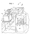
- Figure 1 is a simplified diagrammatic view of an apparatus according to the present invention as it might be implemented in a foundry or a conveyor production line.
- Figure 2 is a simplified diagrammatic representation of the present invention, showing both the mechanical and electronic subsystems of the invention.
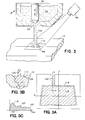
- Figures 3, 3A, 3B and 3C are simplified diagrammatic representations of certain principles of the invention.
- Referring now to the drawings, wherein like numerals indicate like elements, there is shown in Figure 1
apparatus 10 according to the present invention as it would be implemented in a foundry or on a conveyor casting line.Apparatus 10 comprises aconventional conveyor line 12 which transports a plurality ofmolds 14 to casting station 16 wheremolds 14 are filled with molten metal to be cast. As shown in Figure 1,conveyor line 12advances molds 14 from lower left to upper right (as viewed in Figure 1).Conveyor 12 may be of the indexing type, which indexes one mold at a time to a filling location adjacent casting station 16.Conveyor line 12 may also be of the continuous type, on which molds are advanced at constant speed.Conveyor line 12 is well known and well understood in the art, and therefore need not be described in further detail here. - Casting station 16 comprises a
molten metal reservoir 18. As seen in both Figures 1 and 2,reservoir 18 comprises ashell 20 and arefractory lining 22.Shell 20 andrefractory lining 22 are of suitable high-temperature material to containmolten metal 24 to be cast.Reservoir 18 is provvided with a pouropening 26 in its bottom surface through which molten metal is poured into amold 14. The flow of metal through pour opening 26 to mold 14 is controlled by astopper rod 28, which controls the pour of metal fromreservoir 18 in known manner.Stopper rod 28 is operated bylevers pneumatic booster 34.Pneumatic booster 34 is controlled by electric-to-pneumatic transducer assembly 36 in response to electronic control signals generated in a manner to be described in greater detail hereinbelow. -
Stopper rod 28 moves vertically up and down in the direction of the double headed arrow shown in Figure 2. Except for up and down movement,stopper rod 28 is fixed with respect toreservoir 18 so that the axis ofstopper rod 28 is always coaxial with axis of pour opening 26.Pneumatic booster 34, operating levers 30, 32 and electric-to-pneumatic transducer assembly 36 are all fixed toreservoir 18 via a suitable mountingbracket 38. - Casting station 16 also comprises X-Y positioning table 40 which is capable of movement in X-Y directions. The X and Y directions are mutually orthogonal in the hori zontal plane, as shown by the X and Y axes in Figure 1. As best seen in Figure 2, X-Y table 40 is moved in the X direction by a
lead screw 42 andnut 44. Leadscrew 42 is journaled at oneend 46 and rotated at the other end byelectric motor 48.Electric motor 48 is operated by electrical signals generated as will be described in greater detail hereinbelow. Other means for moving table 40 include linear motors, hydraulic cylinders and other suitable means. - X-Y table 40 is mounted for movement in the Y direction on
co-parallel rails foundry floor 54. X-Y table 40 moves in the Y direction onwheels rails lead screw 60 andnut 62. As withlead screw 42,lead screw 60 is journaled at one end and driven at the other end byelectric motor 64.Electric motor 64 is operated by electrical signals generated as will be described in greater detail hereinbelow. - Also fixedly mounted with respect to
reservoir 18 is animage sensor 66 which may be a conventional video camera which generates a continuous video signal, or a digital electronic camera. A digital electronic camera is preferred, although not required, and such cameras are well-known in the art.Camera 66 is focused on the surface ofmold 14 around asprue cup 68, which may but need not be cone-shaped, to acquire a digital image of the surface of the molten metal insprue cup 68 during a pour.Camera 66 is mounted at one end of aviewing tube 70. A quartz screen 72 and aninfrared filter 74 may be provided, if desired, to protectcamera 66 from excessive heat radiated by the molten metal being poured, but are not required. If desired, chilled air or inert gas, depending upon the particular metal being cast, may be introduced intotube 70 throughinlet 76 to generate a positive pressure intube 70 to prevent fumes and dust from enteringtube 70 and interfering with the vision ofcamera 66. The exterior surfaces oftube 70 may be lined with a refractory material, if desired, to withstand the heat of the molten metal being poured. - The various electronic, monitoring, processing and control devices for the present invention, which may be referred to collectively as the electronic subsystem, are best seen in Figure 2. The electronic subsystem is described as it would be configured when a digital
electronic camera 66 is employed. However, modifications to the electronic subsystem for use with a continuous-signal video camera are believed well within the skill in the art. - At the center of the electronic subsystem is a
CPU 78 which may be any well-known microcomputer or microprocessor.CPU 78 communicates with the various components of the electronic subsystem by means ofcomputer bus 80.CPU 78 is operated by a control program stored inmemory 82.Memory 82 be a random access memory (RAM) or any other suitable memory for containing the control program forCPU 78. In addition tomemory 82, for containing the control program, a nonvolatilemass storage memory 84 is provided for storing back-up program and data processed byCPU 78 for later use. - Control commands generated by
CPU 78 are processed through input/output (I/O)interface 86, which converts control commands generated byCPU 78 to a form suitable for use by the E/P driver 88 andX-Y drivers 90. Converted control commands to electric-to-pneumatic transducer assembly 36 are generated by E/P driver 88. Converted control commands tomotors X-Y drivers 90. - The output data from
digital camera 66 are sent tovision interface unit 98.Vision interface unit 98 contains twoframe buffer circuits digital camera 66 can be collected into one buffer while the previously-collected image in the other buffer is being processed byCPU 78. This allows image information to be processed without gaps or "dead times".Vision interface unit 98 communicates withCPU 78 viacomputer bus 80.Vision interface unit 98 also contains other video processing circuits to process the video information into a form suitable for display on a television monitor. Processed video fromvision interface unit 98 is sent to atelevision monitor 94 to provide visual feedback to an operator. If desired, the processed video may also be sent to avideocassette recorder 96, where the signal may be recorded for later analysis or for archival purposes. - A
joystick control 92 and akeyboard 104 are provided to enable an operator to communicate directly withCPU 78 as desired in order to set up the system and provide manual control. ACRT 106 is also provided to give a visual display of various data and operating parameters, other than processed video, as desired. - As best seen in Figure 1, all of the electronic components may be housed in a
booth 108 or other similar structure, so that the electronic components are isolated from the high temperatures of casting station 16. The electronic subsystem may be connected to the mechanical components of the invention through appropriate cabling run inoverhead conduit 110. If desired,booth 108 may be air conditioned to further protect the electronic components from heat and to provide operator comfort. - Operation of the invention will now be described. It will be understood by those skilled in the art that, apart from the broad principles of the invention, the details of operation may be left to those skilled in the art.
- Referring now to Figures 3, 3A, 3B and 3C,
digital camera 66 is focused on the surface ofmold 14 around asprue cup 68, which may be cone-shaped as shown, or which may be any other suitable shape, and acquires a digital image of thesurface 112 of the molten metal in the sprue cup. The image acquired bydigital camera 66 is schematically illustrated in Figure 3A. Reference surface area values, indicated by thelarger trapezoid 116 in Figure 3A, are stored inmemory 82.Shaded portion 114 represents the image ofactual surface 112 viewed bydigital camera 66. This image is sent tovision interface unit 98, and then toCPU 78, one frame at a time. Preferably, a larger number of frames (i.e., a high sampling rate) are acquired when pouring each mold. For example, a typical known digital camera acquires 30 frames per second. The image is processed inCPU 78 and cleared of obstructing artifacts, such as streams, splashes, drops and sparks. The actual surface area ofmolten metal surface 112 is then computed inCPU 78 from the digital image. The reference area is compared with the most recent digital image acquired bydigital camera 66 and a difference value E, representing the difference between the actual surface area and the reference surface area, is computed byCPU 78. A derivative D=dE/dt and integral I = ∫E dt are also computed byCPU 78. At that point, a control value is computed byCPU 78 according to the following formula:
(1) Ci,n = -G(Ei+K₁Di+K₂Ii)
where:
Ci,n = control value
i = sample number
n = pour number
G = gain factor
K₁ = derivative factor
K₂ = integral factor - The control values Ci,n are illustrated in Figure 3C, and are used to drive electric-to-
pneumatic transducer assembly 36 which, in turn, controls the position ofstopper rod 28, therefore controlling the flow of molten metal into the mold. As seen in Figure 3C, the control values which occur at the beginning of a pour (designated generally by 118) are higher in amplitude than the control values of "steady state" pour (designated by 120). This indicates thatstopper rod 28 is fully open at the beginning of a pour, to quickly floodsprue cup 68 with metal. Oncesprue cup 68 is filled, the control values vary during a pour (120) for the duration of the pour, so that flow of meta; into thesprue cup 68 is always equal to the flow inside the mold through the mold gating system. - The control values Ci,n may be adaptively altered after each pour as a function of previous pours in order to minimize the difference E. This can be done by adding socalled offset bias values Bi,n to the control values Ci,n according to the following formula:
(2) Ci,n = -G(Ei+K₁Di+K₂Ii)+Bi,n
where Bi,n are bias values representative of an offset bias given to the control values. - The offset bias Bi,n is computed after each pour as a function of previous pours and the most recent pour, according to the formula:
(3) Bi,n=f(Ci,n, Bi,n-1)
where f (C, B) is an empirically determined function. - The control bias values Bi,n may be set arbitrarily. for the first pour and stored in a table in
CPU 78. Control values Ci,n are stored only for the current pour. For a new pour, while indexingmolds 14, control bias values Bi,n are updated inCPU 78 based on the control signal values of the current pour and the control bias values of the previous pour. Thus, the system is an adaptive one which takes into account differences from previous pours, and minimizes the difference E in just a few pours. - The control bias values Bi,n as set arbitrarily for the first pour are set to accomodate "metal in transit" based on anticipated flow rates for the particular mold being filled. Thus, control bias values Bi,n are chosen to gradually "taper" the flow of molten metal to zero at the end of the pour so that the mold will be precisely filled, without over- or under-filling it. Since the bias values for the first pour, Bi,1, are set arbitrarily, the first mold may in actuality be under- or over-filled. However, the bias values for the second and successive pours, Bi,2, Bi,3,...,Bi,n, are adaptively updated according to equation (2) above so that the flow at the end of the pour is correctly "tapered" based on previous pours and thus flow can be more precisely controlled to precisely fill the succeeding molds.
- In addition to controlling the flow,
CPU 78 also generates correction values for the X and Y positioning ofmetal stream 122 with respect to the axis ofsprue cup 68. The center of the sprue cup is computed inCPU 78 from the most recent acquired image fromdigital camera 66. The center of the pour can be determined when the system is initially adjusted, so that the location of the center of the pour is fixed with respect tocamera 66.CPU 78 generates appropriate command values toX-Y drivers 90 to actuatemotors reservoir 18 so that the center of pour opening 26 coincides with the axis ofsprue cup 68. - Various ways in which
CPU 78 may be programmed to carry out the functions and operations described above will be apparent to those skilled in the art. Such programming details are not crucial to the present invention, and the invention is not limited by the particular program chosen. - The present invention may be embodied in other specific forms without departing from the spirit or essential attributes thereof and, accordingly, reference should be made to the appended claims, rather than to the foregoing specification, as indicating the scope of the invention.
Claims (12)
Priority Applications (1)
| Application Number | Priority Date | Filing Date | Title |
|---|---|---|---|
| AT87309212T ATE81045T1 (en) | 1986-10-20 | 1987-10-19 | DEVICE AND METHOD FOR CONTROLLING THE POURING OF MELT INTO A MOLD. |
Applications Claiming Priority (4)
| Application Number | Priority Date | Filing Date | Title |
|---|---|---|---|
| US92040186A | 1986-10-20 | 1986-10-20 | |
| US920401 | 1986-10-20 | ||
| US06/928,769 US4744407A (en) | 1986-10-20 | 1986-11-10 | Apparatus and method for controlling the pour of molten metal into molds |
| US928769 | 1986-11-10 |
Publications (4)
| Publication Number | Publication Date |
|---|---|
| EP0265206A2 true EP0265206A2 (en) | 1988-04-27 |
| EP0265206A3 EP0265206A3 (en) | 1989-03-22 |
| EP0265206B1 EP0265206B1 (en) | 1992-09-30 |
| EP0265206B2 EP0265206B2 (en) | 2000-01-12 |
Family
ID=27129798
Family Applications (1)
| Application Number | Title | Priority Date | Filing Date |
|---|---|---|---|
| EP87309212A Expired - Lifetime EP0265206B2 (en) | 1986-10-20 | 1987-10-19 | Apparatus and method for controlling the pour of molten metal into molds |
Country Status (4)
| Country | Link |
|---|---|
| US (1) | US4744407A (en) |
| EP (1) | EP0265206B2 (en) |
| DE (1) | DE3781996T3 (en) |
| ES (1) | ES2035078T5 (en) |
Cited By (4)
| Publication number | Priority date | Publication date | Assignee | Title |
|---|---|---|---|---|
| DE4341593A1 (en) * | 1993-12-07 | 1995-06-08 | Abb Patent Gmbh | Process for repositioning a casting system in a baling form and conveyor system |
| EP0747153A1 (en) * | 1995-06-07 | 1996-12-11 | PROGELTA S.r.l. | Facility for casting molten metallic materials having a laser sensor device to control the level of molten metal |
| DE19610613A1 (en) * | 1996-03-18 | 1997-09-25 | Inducal Goellingen Gmbh | Casting furnace with an induction crucible |
| WO2002036293A1 (en) * | 2000-11-03 | 2002-05-10 | Mpc Metal Process Control Ab | Metal flow control |
Families Citing this family (20)
| Publication number | Priority date | Publication date | Assignee | Title |
|---|---|---|---|---|
| US4953761A (en) * | 1988-09-27 | 1990-09-04 | Inductotherm Corp. | Stopper rod spatial control mechanism |
| US5242014A (en) * | 1988-11-30 | 1993-09-07 | Nippon Steel Corporation | Continuous casting method and apparatus for implementing same method |
| US5056584A (en) * | 1989-12-07 | 1991-10-15 | Cmi International, Inc. | Method of and apparatus for pouring molds on a continuously moving conveyor |
| DE4103243A1 (en) * | 1990-02-21 | 1991-08-29 | Inductotherm Corp | METHOD FOR CONTROLLING THE POURING OF A LIQUID FROM A VESSEL IN INDIVIDUAL CASTING MOLDS AND DEVICE FOR IMPLEMENTING THE METHOD |
| US5097888A (en) * | 1990-09-17 | 1992-03-24 | Augustine Iii Robert B | Casting flow control system |
| DE4202020A1 (en) * | 1992-01-25 | 1993-07-29 | Abb Patent Gmbh | Precise positioning of casting system - above mould sprue in boxless mould making and conveying |
| US5312090A (en) * | 1992-12-14 | 1994-05-17 | Cmi International | Apparatus and method for controlling a stopper rod of a bottom pouring vessel |
| ES2136808T3 (en) * | 1995-06-07 | 1999-12-01 | Inductotherm Corp | VIDEO POSITIONING SYSTEM FOR A SPILL CONTAINER. |
| DE19821401C2 (en) * | 1998-05-13 | 2000-05-18 | Storz Endoskop Gmbh Schaffhaus | Endoscope for inspection of an observation room |
| US6859285B1 (en) * | 1999-08-31 | 2005-02-22 | Og Technologies, Inc. | Optical observation device and method for observing articles at elevated temperatures |
| FI20011334A (en) * | 2001-06-21 | 2002-12-22 | Abb Installaatiot Oy | Procedure and apparatus for basic control of liquid medium transport systems |
| SE523881C2 (en) * | 2001-09-27 | 2004-05-25 | Abb Ab | Device and method of continuous casting |
| US6896032B1 (en) * | 2002-09-26 | 2005-05-24 | Hayes Lemmerz International, Inc. | Stopper-poured molten metal casting vessel with constant head height |
| DE10324247A1 (en) * | 2003-05-28 | 2004-12-16 | Bayerische Motoren Werke Ag | Metal casting plant and process |
| US20070045913A1 (en) * | 2005-08-29 | 2007-03-01 | Titanium Metals Corp. | System for detecting entry of foreign material during melting |
| US8701948B2 (en) | 2009-05-10 | 2014-04-22 | Inductotherm Corp. | Stopper rod positioning and control apparatus for control of molten metal flow through a nozzle |
| JP5867714B2 (en) * | 2012-01-30 | 2016-02-24 | マツダ株式会社 | Casting method for castings |
| BR112015012978B1 (en) * | 2012-12-04 | 2021-03-30 | Ingo Stork (Genannt) Wersborg | SYSTEM FOR MONITORING A HEAT TREATMENT |
| AT515244A2 (en) | 2013-12-30 | 2015-07-15 | Inteco Special Melting Technologies Gmbh | Method for producing long ingots of large cross section |
| CN115283659B (en) * | 2022-08-08 | 2023-07-04 | 河北师范大学 | Fixed point casting system based on artificial intelligence |
Citations (4)
| Publication number | Priority date | Publication date | Assignee | Title |
|---|---|---|---|---|
| US3838727A (en) | 1973-07-16 | 1974-10-01 | I Levi | Normalized optical input level control in continuous casting process and apparatus |
| DE2631015A1 (en) | 1975-10-29 | 1977-05-12 | Hitachi Ltd | AUTOMATIC METAL MELT CASTING SYSTEM |
| US4304287A (en) | 1977-09-05 | 1981-12-08 | Maschinenfabrik & Eisengiesserei | Flow cut-off method for foundry installations |
| DD206950A1 (en) | 1981-12-31 | 1984-02-15 | Frank Huebsch | ARRANGEMENT FOR OUTPUT POWER REGULATION OF A TIPPING PAN |
Family Cites Families (32)
| Publication number | Priority date | Publication date | Assignee | Title |
|---|---|---|---|---|
| US2743492A (en) * | 1953-04-20 | 1956-05-01 | Allegheny Ludlum Steel | Apparatus for controlling the flow of molten metal |
| US3122800A (en) * | 1961-05-01 | 1964-03-03 | Gen Motors Corp | Automatic metal pouring machine |
| US3537505A (en) * | 1965-12-30 | 1970-11-03 | Concast Ag | Method of controlling continuous casting |
| US3636360A (en) * | 1968-05-13 | 1972-01-18 | Hitachi Ltd | Apparatus for detection of liquid level in transparent tube comprising photocell located to receive light which has been totally reflected |
| US3570449A (en) * | 1969-03-13 | 1971-03-16 | United Aircraft Corp | Sensor system for a vacuum deposition apparatus |
| US3590777A (en) * | 1969-03-13 | 1971-07-06 | United Aircarft Corp | Ingot feed drive |
| US3643724A (en) * | 1970-03-26 | 1972-02-22 | United States Steel Corp | Method of indicating the level of a molten fluid |
| US3633010A (en) * | 1970-05-04 | 1972-01-04 | Geosystems Inc | Computer-aided laser-based measurement system |
| US3730254A (en) * | 1970-12-18 | 1973-05-01 | Creusot Loire | Roller pair type continuous casting apparatus |
| US3741656A (en) * | 1971-05-27 | 1973-06-26 | Bendix Corp | Fill level measuring device |
| SE364654B (en) * | 1971-11-18 | 1974-03-04 | Asea Ab | |
| CH551821A (en) * | 1972-10-17 | 1974-07-31 | Concast Ag | PROCESS AND EQUIPMENT FOR REGULATING THE LEVEL OF THE MELT IN MOLDS OF CONTINUOUS CASTING PLANTS. |
| US3842894A (en) * | 1973-01-17 | 1974-10-22 | American Metal Climax Inc | Automatic means for remote sweep-scanning of a liquid level and for controlling flow to maintain such level |
| JPS5210646B2 (en) * | 1973-07-18 | 1977-03-25 | ||
| DE2506190C2 (en) * | 1974-09-26 | 1985-08-29 | Ceda S.p.A., Buttrio, Udine | Device for regulating the level of a liquid in a container which emits infrared rays |
| DE2543168C3 (en) * | 1975-09-27 | 1980-05-29 | Brown, Boveri & Cie Ag, 6800 Mannheim | Mobile pouring device |
| US4112998A (en) * | 1975-10-22 | 1978-09-12 | Fujiwa Kika Kabushiki Kaisha | Pouring method and apparatus therefor |
| DE2706558A1 (en) * | 1976-03-15 | 1977-09-22 | Erwin Buehrer | METHOD AND EQUIPMENT FOR PASTING A MOLD WITH A SELECTABLE QUANTITY OF LIQUID METAL |
| CH615609A5 (en) * | 1976-03-22 | 1980-02-15 | Mezger Ed Maschinenfabrik & Ei | |
| JPS5351138A (en) * | 1976-10-22 | 1978-05-10 | Hitachi Metals Ltd | Automatic pouring method of molten metal |
| LU76077A1 (en) * | 1976-10-26 | 1978-05-16 | ||
| LU79390A1 (en) * | 1978-04-06 | 1979-11-07 | Metallurgie Hoboken | CONTINUOUS CASTING PROCESS OF A METAL AND APPARATUS FOR ITS IMPLEMENTATION |
| FR2429632A1 (en) * | 1978-06-28 | 1980-01-25 | Est Aciers Fins | DEVICE FOR ADJUSTING THE FLOW RATE OF A PLUG OF A DISPENSING CONTAINER IN A CONTINUOUS CASTING SYSTEM, BY CONTROLLING AT THE METAL BATH OF A RECEIVING LINGOTIERE |
| US4247784A (en) * | 1978-12-18 | 1981-01-27 | Eastman Kodak Company | Measurement of material level in vessels |
| CH629130A5 (en) * | 1979-06-07 | 1982-04-15 | Mezger Ed Maschinenfabrik & Ei | AUTOMATICALLY CONTROLLED CASTING INSTALLATION. |
| US4354180A (en) * | 1980-12-19 | 1982-10-12 | Genelco, Inc. | Electro-optical liquid level sensor |
| SU984668A1 (en) * | 1981-06-03 | 1982-12-30 | Украинский Государственный Проектный Институт "Металлургавтоматика" | Apparatus for automatization of steel casting into ingot mould |
| US4620353A (en) * | 1981-06-15 | 1986-11-04 | Pryor Timothy R | Electro-optical and robotic casting quality assurance |
| US4453083A (en) * | 1981-10-26 | 1984-06-05 | Betriebsforschungsinstitut Vdeh Institut Fur Angewandte Forschung Gmbh | Apparatus for the determination of the position of a surface |
| JPS58110169A (en) * | 1981-12-23 | 1983-06-30 | Asahi Malleable Iron Co Ltd | Charging method |
| SE441502B (en) * | 1984-03-19 | 1985-10-14 | Asea Ab | NIVAMETERS BY COCILLES FOR STRING |
| US4673025A (en) * | 1986-04-04 | 1987-06-16 | Inductotherm Corporation | Apparatus and method for maintaining constant molten metal level in metal casting |
-
1986
- 1986-11-10 US US06/928,769 patent/US4744407A/en not_active Expired - Lifetime
-
1987
- 1987-10-19 ES ES87309212T patent/ES2035078T5/en not_active Expired - Lifetime
- 1987-10-19 DE DE3781996T patent/DE3781996T3/en not_active Expired - Fee Related
- 1987-10-19 EP EP87309212A patent/EP0265206B2/en not_active Expired - Lifetime
Patent Citations (4)
| Publication number | Priority date | Publication date | Assignee | Title |
|---|---|---|---|---|
| US3838727A (en) | 1973-07-16 | 1974-10-01 | I Levi | Normalized optical input level control in continuous casting process and apparatus |
| DE2631015A1 (en) | 1975-10-29 | 1977-05-12 | Hitachi Ltd | AUTOMATIC METAL MELT CASTING SYSTEM |
| US4304287A (en) | 1977-09-05 | 1981-12-08 | Maschinenfabrik & Eisengiesserei | Flow cut-off method for foundry installations |
| DD206950A1 (en) | 1981-12-31 | 1984-02-15 | Frank Huebsch | ARRANGEMENT FOR OUTPUT POWER REGULATION OF A TIPPING PAN |
Cited By (8)
| Publication number | Priority date | Publication date | Assignee | Title |
|---|---|---|---|---|
| DE4341593A1 (en) * | 1993-12-07 | 1995-06-08 | Abb Patent Gmbh | Process for repositioning a casting system in a baling form and conveyor system |
| EP0659504A2 (en) * | 1993-12-07 | 1995-06-28 | ABBPATENT GmbH | Method for repositioning of a casting system for a form- and transportsystem which presses balers |
| EP0659504A3 (en) * | 1993-12-07 | 1996-12-18 | Abb Patent Gmbh | Method for repositioning of a casting system for a form- and transportsystem which presses balers. |
| EP0747153A1 (en) * | 1995-06-07 | 1996-12-11 | PROGELTA S.r.l. | Facility for casting molten metallic materials having a laser sensor device to control the level of molten metal |
| DE19610613A1 (en) * | 1996-03-18 | 1997-09-25 | Inducal Goellingen Gmbh | Casting furnace with an induction crucible |
| WO2002036293A1 (en) * | 2000-11-03 | 2002-05-10 | Mpc Metal Process Control Ab | Metal flow control |
| US7013949B2 (en) | 2000-11-03 | 2006-03-21 | Mpc Metal Process Controll Ab | Metal flow control |
| KR100846250B1 (en) * | 2000-11-03 | 2008-07-16 | 엠피씨 메탈 프로세스 컨트롤 에이비 | Metal flow control |
Also Published As
| Publication number | Publication date |
|---|---|
| EP0265206B2 (en) | 2000-01-12 |
| DE3781996D1 (en) | 1992-11-05 |
| ES2035078T3 (en) | 1993-04-16 |
| US4744407A (en) | 1988-05-17 |
| ES2035078T5 (en) | 2000-04-01 |
| EP0265206A3 (en) | 1989-03-22 |
| DE3781996T2 (en) | 1993-03-11 |
| EP0265206B1 (en) | 1992-09-30 |
| DE3781996T3 (en) | 2000-07-27 |
Similar Documents
| Publication | Publication Date | Title |
|---|---|---|
| EP0265206A2 (en) | Apparatus and method for controlling the pour of molten metal into molds | |
| US5381855A (en) | Method of and apparatus for controlling the motion of a pouring ladle | |
| EP2008741A1 (en) | Automatic pouring method and storage medium storing ladle tilting control program | |
| US4770230A (en) | Process and apparatus for starting a continuous casting plant | |
| GB2146463A (en) | Liquid-level control | |
| JP2540032B2 (en) | Method for starting a continuous casting machine with multiple slabs | |
| US5758714A (en) | Method of automatically pouring molten metal and apparatus therefor | |
| US4708193A (en) | Process for removing deposits from the flow channel of a tundish during continuous casting | |
| US4299268A (en) | Automatically controlled casting plant | |
| US4226278A (en) | Automatic molten metal surface level control system for continuous casting machines | |
| JPH04220157A (en) | Controlling device for pouring molten material into mold and its method | |
| JPH02247074A (en) | Casting machine of molten metal | |
| US5031805A (en) | Processes and device for dosing free-flowing media | |
| JP3361369B2 (en) | Automatic pouring method and apparatus | |
| JPH08168871A (en) | Apparatus for pouring molten metal | |
| GB2057937A (en) | Casting metals using bottom pouring | |
| JPH0763835B2 (en) | Vacuum casting method and apparatus | |
| EP0400302A3 (en) | Method of and installation for filling a continuous casting mold with molten metal | |
| US6779585B2 (en) | Method for controlling ladle motion to reduce aluminum oxide formation | |
| SE465711B (en) | SEAT AND DEVICE FOR CASTING METAL | |
| JPH02243728A (en) | Purified melting for super alloy | |
| AU716841B2 (en) | Method for vertical,continuous casting of metals | |
| CN107199328A (en) | A kind of full-automatic bottom filling full-automobile casting machine of use video monitoring | |
| CN114309573B (en) | Molten aluminum discharge control method in smelting furnace | |
| JPH08269531A (en) | Method and device for detecting position of tapping steel stream of converter |
Legal Events
| Date | Code | Title | Description |
|---|---|---|---|
| PUAI | Public reference made under article 153(3) epc to a published international application that has entered the european phase |
Free format text: ORIGINAL CODE: 0009012 |
|
| AK | Designated contracting states |
Kind code of ref document: A2 Designated state(s): AT BE CH DE ES FR GB GR IT LI LU NL SE |
|
| PUAL | Search report despatched |
Free format text: ORIGINAL CODE: 0009013 |
|
| AK | Designated contracting states |
Kind code of ref document: A3 Designated state(s): AT BE CH DE ES FR GB GR IT LI LU NL SE |
|
| 17P | Request for examination filed |
Effective date: 19890913 |
|
| 17Q | First examination report despatched |
Effective date: 19910207 |
|
| GRAA | (expected) grant |
Free format text: ORIGINAL CODE: 0009210 |
|
| AK | Designated contracting states |
Kind code of ref document: B1 Designated state(s): AT BE CH DE ES FR GB GR IT LI LU NL SE |
|
| PG25 | Lapsed in a contracting state [announced via postgrant information from national office to epo] |
Ref country code: GR Free format text: LAPSE BECAUSE OF FAILURE TO SUBMIT A TRANSLATION OF THE DESCRIPTION OR TO PAY THE FEE WITHIN THE PRESCRIBED TIME-LIMIT Effective date: 19920930 |
|
| REF | Corresponds to: |
Ref document number: 81045 Country of ref document: AT Date of ref document: 19921015 Kind code of ref document: T |
|
| ET | Fr: translation filed | ||
| PG25 | Lapsed in a contracting state [announced via postgrant information from national office to epo] |
Ref country code: LU Free format text: LAPSE BECAUSE OF NON-PAYMENT OF DUE FEES Effective date: 19921031 |
|
| REF | Corresponds to: |
Ref document number: 3781996 Country of ref document: DE Date of ref document: 19921105 |
|
| ITF | It: translation for a ep patent filed |
Owner name: SOCIETA' ITALIANA BREVE |
|
| REG | Reference to a national code |
Ref country code: ES Ref legal event code: FG2A Ref document number: 2035078 Country of ref document: ES Kind code of ref document: T3 |
|
| PLBI | Opposition filed |
Free format text: ORIGINAL CODE: 0009260 |
|
| 26 | Opposition filed |
Opponent name: ABB PATENT GMBH Effective date: 19930623 |
|
| NLR1 | Nl: opposition has been filed with the epo |
Opponent name: ABB PATENT GMBH |
|
| EAL | Se: european patent in force in sweden |
Ref document number: 87309212.6 |
|
| PLAW | Interlocutory decision in opposition |
Free format text: ORIGINAL CODE: EPIDOS IDOP |
|
| APAA | Appeal reference recorded |
Free format text: ORIGINAL CODE: EPIDOS REFN |
|
| APAC | Appeal dossier modified |
Free format text: ORIGINAL CODE: EPIDOS NOAPO |
|
| APAC | Appeal dossier modified |
Free format text: ORIGINAL CODE: EPIDOS NOAPO |
|
| APAE | Appeal reference modified |
Free format text: ORIGINAL CODE: EPIDOS REFNO |
|
| APAC | Appeal dossier modified |
Free format text: ORIGINAL CODE: EPIDOS NOAPO |
|
| PLAW | Interlocutory decision in opposition |
Free format text: ORIGINAL CODE: EPIDOS IDOP |
|
| PLBQ | Unpublished change to opponent data |
Free format text: ORIGINAL CODE: EPIDOS OPPO |
|
| PLBQ | Unpublished change to opponent data |
Free format text: ORIGINAL CODE: EPIDOS OPPO |
|
| PLAB | Opposition data, opponent's data or that of the opponent's representative modified |
Free format text: ORIGINAL CODE: 0009299OPPO |
|
| PUAH | Patent maintained in amended form |
Free format text: ORIGINAL CODE: 0009272 |
|
| STAA | Information on the status of an ep patent application or granted ep patent |
Free format text: STATUS: PATENT MAINTAINED AS AMENDED |
|
| R26 | Opposition filed (corrected) |
Opponent name: ABB PATENT GMBH Effective date: 19930623 |
|
| 27A | Patent maintained in amended form |
Effective date: 20000112 |
|
| AK | Designated contracting states |
Kind code of ref document: B2 Designated state(s): AT BE CH DE ES FR GB GR IT LI LU NL SE |
|
| REG | Reference to a national code |
Ref country code: CH Ref legal event code: AEN Free format text: MAINTIEN DU BREVET DONT L'ETENDUE A ETE MODIFIEE |
|
| NLR1 | Nl: opposition has been filed with the epo |
Opponent name: ABB PATENT GMBH |
|
| NLR2 | Nl: decision of opposition | ||
| REG | Reference to a national code |
Ref country code: ES Ref legal event code: DC2A Kind code of ref document: T5 Effective date: 20000301 |
|
| ITF | It: translation for a ep patent filed |
Owner name: SOCIETA' ITALIANA BREVETTI S.P.A. |
|
| ET3 | Fr: translation filed ** decision concerning opposition | ||
| NLR3 | Nl: receipt of modified translations in the netherlands language after an opposition procedure | ||
| REG | Reference to a national code |
Ref country code: GB Ref legal event code: IF02 |
|
| PGFP | Annual fee paid to national office [announced via postgrant information from national office to epo] |
Ref country code: NL Payment date: 20020919 Year of fee payment: 16 |
|
| PG25 | Lapsed in a contracting state [announced via postgrant information from national office to epo] |
Ref country code: NL Free format text: LAPSE BECAUSE OF NON-PAYMENT OF DUE FEES Effective date: 20040501 |
|
| NLV4 | Nl: lapsed or anulled due to non-payment of the annual fee |
Effective date: 20040501 |
|
| APAH | Appeal reference modified |
Free format text: ORIGINAL CODE: EPIDOSCREFNO |
|
| PGFP | Annual fee paid to national office [announced via postgrant information from national office to epo] |
Ref country code: AT Payment date: 20051012 Year of fee payment: 19 |
|
| PGFP | Annual fee paid to national office [announced via postgrant information from national office to epo] |
Ref country code: DE Payment date: 20051014 Year of fee payment: 19 |
|
| PGFP | Annual fee paid to national office [announced via postgrant information from national office to epo] |
Ref country code: SE Payment date: 20061004 Year of fee payment: 20 |
|
| PGFP | Annual fee paid to national office [announced via postgrant information from national office to epo] |
Ref country code: CH Payment date: 20061013 Year of fee payment: 20 |
|
| PGFP | Annual fee paid to national office [announced via postgrant information from national office to epo] |
Ref country code: GB Payment date: 20061018 Year of fee payment: 20 |
|
| PG25 | Lapsed in a contracting state [announced via postgrant information from national office to epo] |
Ref country code: AT Free format text: LAPSE BECAUSE OF NON-PAYMENT OF DUE FEES Effective date: 20061019 |
|
| PGFP | Annual fee paid to national office [announced via postgrant information from national office to epo] |
Ref country code: IT Payment date: 20061031 Year of fee payment: 20 |
|
| PGFP | Annual fee paid to national office [announced via postgrant information from national office to epo] |
Ref country code: ES Payment date: 20061124 Year of fee payment: 20 |
|
| PGFP | Annual fee paid to national office [announced via postgrant information from national office to epo] |
Ref country code: BE Payment date: 20061218 Year of fee payment: 20 |
|
| PG25 | Lapsed in a contracting state [announced via postgrant information from national office to epo] |
Ref country code: DE Free format text: LAPSE BECAUSE OF NON-PAYMENT OF DUE FEES Effective date: 20070501 |
|
| REG | Reference to a national code |
Ref country code: CH Ref legal event code: PFA Owner name: INDUCTOTHERM CORP. Free format text: INDUCTOTHERM CORP.#10 INDEL AVENUE#RANCOCAS/NJ (US) -TRANSFER TO- INDUCTOTHERM CORP.#10 INDEL AVENUE#RANCOCAS/NJ (US) |
|
| REG | Reference to a national code |
Ref country code: GB Ref legal event code: PE20 |
|
| REG | Reference to a national code |
Ref country code: CH Ref legal event code: PL |
|
| BE20 | Be: patent expired |
Owner name: *INDUCTOTHERM CORP. Effective date: 20071019 |
|
| REG | Reference to a national code |
Ref country code: ES Ref legal event code: FD2A Effective date: 20071020 |
|
| PG25 | Lapsed in a contracting state [announced via postgrant information from national office to epo] |
Ref country code: GB Free format text: LAPSE BECAUSE OF EXPIRATION OF PROTECTION Effective date: 20071018 Ref country code: ES Free format text: LAPSE BECAUSE OF EXPIRATION OF PROTECTION Effective date: 20071020 |
|
| PGFP | Annual fee paid to national office [announced via postgrant information from national office to epo] |
Ref country code: FR Payment date: 20061010 Year of fee payment: 20 |