EP0263881B1 - Hermetically sealed lead storage battery - Google Patents
Hermetically sealed lead storage battery Download PDFInfo
- Publication number
- EP0263881B1 EP0263881B1 EP87901686A EP87901686A EP0263881B1 EP 0263881 B1 EP0263881 B1 EP 0263881B1 EP 87901686 A EP87901686 A EP 87901686A EP 87901686 A EP87901686 A EP 87901686A EP 0263881 B1 EP0263881 B1 EP 0263881B1
- Authority
- EP
- European Patent Office
- Prior art keywords
- metal plate
- storage battery
- sealed lead
- casing
- electrodes
- Prior art date
- Legal status (The legal status is an assumption and is not a legal conclusion. Google has not performed a legal analysis and makes no representation as to the accuracy of the status listed.)
- Expired - Lifetime
Links
- 238000003860 storage Methods 0.000 title claims abstract description 22
- 229910052751 metal Inorganic materials 0.000 claims abstract description 30
- 239000002184 metal Substances 0.000 claims abstract description 30
- 239000003822 epoxy resin Substances 0.000 claims abstract description 15
- 229920000647 polyepoxide Polymers 0.000 claims abstract description 15
- 229920005989 resin Polymers 0.000 claims abstract description 5
- 239000011347 resin Substances 0.000 claims abstract description 5
- 229920000098 polyolefin Polymers 0.000 claims abstract description 4
- 239000002253 acid Substances 0.000 claims description 24
- 229920005672 polyolefin resin Polymers 0.000 claims description 11
- VGGSQFUCUMXWEO-UHFFFAOYSA-N Ethene Chemical compound C=C VGGSQFUCUMXWEO-UHFFFAOYSA-N 0.000 claims description 4
- 239000005977 Ethylene Substances 0.000 claims description 4
- -1 polyethylene terephthalate Polymers 0.000 claims description 4
- 229920000139 polyethylene terephthalate Polymers 0.000 claims description 3
- 239000005020 polyethylene terephthalate Substances 0.000 claims description 3
- 229910000831 Steel Inorganic materials 0.000 claims description 2
- 239000003365 glass fiber Substances 0.000 claims description 2
- 239000010959 steel Substances 0.000 claims description 2
- 230000002093 peripheral effect Effects 0.000 claims 2
- 229920003002 synthetic resin Polymers 0.000 abstract 3
- 239000000057 synthetic resin Substances 0.000 abstract 3
- 229920001169 thermoplastic Polymers 0.000 abstract 2
- 239000004416 thermosoftening plastic Substances 0.000 abstract 2
- 238000000034 method Methods 0.000 description 9
- 230000001070 adhesive effect Effects 0.000 description 6
- 239000000853 adhesive Substances 0.000 description 5
- 238000003825 pressing Methods 0.000 description 5
- 238000007789 sealing Methods 0.000 description 5
- 229910000978 Pb alloy Inorganic materials 0.000 description 3
- 239000004698 Polyethylene Substances 0.000 description 3
- 229920000573 polyethylene Polymers 0.000 description 3
- 229920013716 polyethylene resin Polymers 0.000 description 3
- 238000007796 conventional method Methods 0.000 description 2
- 239000003792 electrolyte Substances 0.000 description 2
- 229920005992 thermoplastic resin Polymers 0.000 description 2
- 238000003466 welding Methods 0.000 description 2
- 239000004411 aluminium Substances 0.000 description 1
- 229910052782 aluminium Inorganic materials 0.000 description 1
- XAGFODPZIPBFFR-UHFFFAOYSA-N aluminium Chemical compound [Al] XAGFODPZIPBFFR-UHFFFAOYSA-N 0.000 description 1
- 230000007423 decrease Effects 0.000 description 1
- 238000005516 engineering process Methods 0.000 description 1
- 230000004927 fusion Effects 0.000 description 1
- 238000009434 installation Methods 0.000 description 1
- 238000004519 manufacturing process Methods 0.000 description 1
- 239000004745 nonwoven fabric Substances 0.000 description 1
- 229920006267 polyester film Polymers 0.000 description 1
- 239000010935 stainless steel Substances 0.000 description 1
- 229910001220 stainless steel Inorganic materials 0.000 description 1
Images

Classifications
-
- H—ELECTRICITY
- H01—ELECTRIC ELEMENTS
- H01M—PROCESSES OR MEANS, e.g. BATTERIES, FOR THE DIRECT CONVERSION OF CHEMICAL ENERGY INTO ELECTRICAL ENERGY
- H01M10/00—Secondary cells; Manufacture thereof
- H01M10/06—Lead-acid accumulators
- H01M10/12—Construction or manufacture
- H01M10/126—Small-sized flat cells or batteries for portable equipment
-
- H—ELECTRICITY
- H01—ELECTRIC ELEMENTS
- H01M—PROCESSES OR MEANS, e.g. BATTERIES, FOR THE DIRECT CONVERSION OF CHEMICAL ENERGY INTO ELECTRICAL ENERGY
- H01M50/00—Constructional details or processes of manufacture of the non-active parts of electrochemical cells other than fuel cells, e.g. hybrid cells
- H01M50/30—Arrangements for facilitating escape of gases
- H01M50/317—Re-sealable arrangements
- H01M50/325—Re-sealable arrangements comprising deformable valve members, e.g. elastic or flexible valve members
-
- H—ELECTRICITY
- H01—ELECTRIC ELEMENTS
- H01M—PROCESSES OR MEANS, e.g. BATTERIES, FOR THE DIRECT CONVERSION OF CHEMICAL ENERGY INTO ELECTRICAL ENERGY
- H01M50/00—Constructional details or processes of manufacture of the non-active parts of electrochemical cells other than fuel cells, e.g. hybrid cells
- H01M50/50—Current conducting connections for cells or batteries
- H01M50/543—Terminals
- H01M50/547—Terminals characterised by the disposition of the terminals on the cells
- H01M50/548—Terminals characterised by the disposition of the terminals on the cells on opposite sides of the cell
-
- H—ELECTRICITY
- H01—ELECTRIC ELEMENTS
- H01M—PROCESSES OR MEANS, e.g. BATTERIES, FOR THE DIRECT CONVERSION OF CHEMICAL ENERGY INTO ELECTRICAL ENERGY
- H01M50/00—Constructional details or processes of manufacture of the non-active parts of electrochemical cells other than fuel cells, e.g. hybrid cells
- H01M50/50—Current conducting connections for cells or batteries
- H01M50/543—Terminals
- H01M50/562—Terminals characterised by the material
-
- H—ELECTRICITY
- H01—ELECTRIC ELEMENTS
- H01M—PROCESSES OR MEANS, e.g. BATTERIES, FOR THE DIRECT CONVERSION OF CHEMICAL ENERGY INTO ELECTRICAL ENERGY
- H01M10/00—Secondary cells; Manufacture thereof
- H01M10/34—Gastight accumulators
- H01M10/342—Gastight lead accumulators
-
- Y—GENERAL TAGGING OF NEW TECHNOLOGICAL DEVELOPMENTS; GENERAL TAGGING OF CROSS-SECTIONAL TECHNOLOGIES SPANNING OVER SEVERAL SECTIONS OF THE IPC; TECHNICAL SUBJECTS COVERED BY FORMER USPC CROSS-REFERENCE ART COLLECTIONS [XRACs] AND DIGESTS
- Y02—TECHNOLOGIES OR APPLICATIONS FOR MITIGATION OR ADAPTATION AGAINST CLIMATE CHANGE
- Y02E—REDUCTION OF GREENHOUSE GAS [GHG] EMISSIONS, RELATED TO ENERGY GENERATION, TRANSMISSION OR DISTRIBUTION
- Y02E60/00—Enabling technologies; Technologies with a potential or indirect contribution to GHG emissions mitigation
- Y02E60/10—Energy storage using batteries
-
- Y—GENERAL TAGGING OF NEW TECHNOLOGICAL DEVELOPMENTS; GENERAL TAGGING OF CROSS-SECTIONAL TECHNOLOGIES SPANNING OVER SEVERAL SECTIONS OF THE IPC; TECHNICAL SUBJECTS COVERED BY FORMER USPC CROSS-REFERENCE ART COLLECTIONS [XRACs] AND DIGESTS
- Y02—TECHNOLOGIES OR APPLICATIONS FOR MITIGATION OR ADAPTATION AGAINST CLIMATE CHANGE
- Y02P—CLIMATE CHANGE MITIGATION TECHNOLOGIES IN THE PRODUCTION OR PROCESSING OF GOODS
- Y02P70/00—Climate change mitigation technologies in the production process for final industrial or consumer products
- Y02P70/50—Manufacturing or production processes characterised by the final manufactured product
Definitions
- the present invention relates to the improvement of a sealed lead-acid storage battery being used as power source of portable apparatus or the like and provides a lead-acid storage battery that the assembling process is simple and is speedily completed, the cost is low, the reliability is high, and the volumetric efficiency is excellent.
- a conventional sealed lead-acid storage battery is constructed as shown in Fig. 2 which is used as power source of portable apparatus or the like.
- numeral 1 denotes a casing made of a thermoplastic resin and receiving a gorup of electrodes 6 composed of a positive electrode 2, a negative electrode 3, and a separator 4.
- An opening portion of a casing 1 surrounding the periphery of the group of the electrodes 6 is hermetically sealed, when the opening portion is thermally bonded to a periphery of a metal plate 7 for a battery casing, an inner surface of which metal plate has been already laminated with a polyethylene film or the like.
- Numeral 5 denotes a pole bar portion
- numeral 8 denotes a vent valve formed at the casing 1 and having the function of opening the valve with the increment of the inner pressure of the battery.
- the method for sealing completely the pole bar portion 5 will be described hereinbelow.
- One method is that an adhesive such as an epoxy resin is filled and hardened.
- the other method is that a sheet of lead alloy coated previously with the epoxy resin or a polyethylene resin is welded to a protruding portion of the electrode by TIG welding or the like to form a pole bar, and the resulting pole bar is thermally bonded between the casing and the metal plate for a battery casing.
- the hardening of adhesive usually requires approximately one hour at 60 o C because the adhesive such as the epoxyresin or the like is used for sealing of the pole bar portion 5.
- the adhesive such as the epoxyresin or the like is used for sealing of the pole bar portion 5.
- it is impossible to improve production capacity in producing process.
- the sheet of lead alloy coated with the epoxy resin or the polyethylene resin is welded to the protruding portion, it was difficult to construct efficiently assembling line of sealed lead-acid storage battery at a high-speed and low cost, since there was a problem in reliability of welding and cost.
- the present invention has been developed in view of the above-mentioned drawbacks and contemplates to provide an improved sealed lead-acid storage battery described hereinbelow. Owing to the fact that a protruding portion of an electrode is coated with an epoxy resin and a polyolefin resin and therefore it is possible to bond thermally the protruding portion with a casing and one surface of metal plate coated with a polyolefin film or the like, it is possible to make an assembling line for assembling the battery with efficiency at high-speed. As a result, the sealed lead-acid storage battery can be made which has a high volumetric efficiency and is of low cost.
- the sealing structure of the pole bar portion is characterized in the next point described below.
- the protruding portion of each of the electrode is directly coated with the epoxy resin and the polyolefin resin, a group of electrodes is thereafter sandwiched between the casing made of a thermoplastic resin and surrounding the periphery of a group of electrodes and metal plate whose inner surface is laminated with a polyolefin film, and then, on thermal bonding of the casing and the metal plates, the protruding portions of electrodes are also thermally bonded to them for sealing the opening, instead of that conventionally, the above-mentioned epoxy resin adhesive is used for adhesion, and a sheet of lead alloy coated with the epoxy resin and the polyolefin resin is welded to the porotruding portion of the electrode, and then, the resulting part is thermally bonded to the casing.
- the process and installation for assembling the battery are simplified and it is possible to shorten largely the operation time of opening-sealing process by this structure, the battery can be assembled at a high-speed.
- the sealed lead-acid storage battery of low cost, high reliability, and excellent volumetric efficiency can be provided.
- the casing of the battery casing and the pressing plate of the cushion are formed integrally, the joint portion of the pressing plate is formed such that the thickness of the joint portion is thinner than that of the pressing plate, thereby being easy to be bent by the function of the hinge, and the pressing plate fitting portion of the opening of the concave portion is provided with a concave portion and a convex portion.
- the pressing plate fitting portion of the opening of the concave portion is provided with a concave portion and a convex portion.
- Fig. 1 shows a sealed lead-acid storage battery of the present invention
- numeral 1 denotes a casing made of a polyolefin resin such as a polyethylene resin, which casing surrounds a periphery of a group of electrodes.
- a protruding portion of an electrode 5a is directly coated with an epoxy resin which is superior in heat resistance and adhesive property, the epoxy resin thereafter is hardened, and then the resulting surface is again coated with a modified-polyethylene solution.
- the group of electrodes 6 comprises a positive electrode 2 and a negative electrode 3 each having a protruding portion coated as described above, and a separator 4 made of nonwoven fabric mainly composed of glass fiber of diameter less than 5 ⁇ m, which separator 4 is superior in absorbing power of electrolyte.
- the group of electrodes 6 is received in the casing 1.
- a metal plate 7 for a battery casing is used an aluminium plate, a stainless steel plate, or a tinned steel plate.
- a thermally bondable polyethylene or polyester film is bonded, and especially, a thermally bondable film or sheet including one body with three layers consisting of an ethylene acrilic acid (EAA) layer, a polyethylene terephthalate (PET) layer, and another ethylene acrilic acid (EAA) layer, which film or sheet has been improved in acid resistance and strength on thermal bonding, is laminated to one surface of the metal plate by means of adhesion or bonding by fusion.
- EAA ethylene acrilic acid
- PET polyethylene terephthalate
- EAA ethylene acrilic acid
- the group of electrodes is sandwiched between two metal plates 7 with the resin film layer of each of the metal plates being opposed to the group of electrodes, and then the rim of the metal plates 7 and the rim of the opening of the casing 1 are thermally bonded each other.
- the casing 1 are provided in advance, a shallow, slender and long concave portion 18 in which the protruding portion of the electrodes 5a is fitted on thermal bonding, and a vent valve 8 arranged to be opened when the inner pressure of the battery rises above a predetermined value.
- the protruding portions 5a also are thermally bonded to the casing 1 and thermal bonding film on one side of the metal plates 7.
- the separator is impregnated with the electrolyte indispensable to the battery in advance before this thermal bonding.
- an uncoated edge of the protruding portion of the electrode 5a arranged to be fitted in the concave portion 18 of the casing 1 made of a resin is spot-welded or the like to a film-removed portion of inner edge portion of the metal plate 7 for battery casing to connect each other electrically, so that the metal plate for battery casing 7 is used as an external terminal.
- the protruding portions 5a of the electrodes of the pole bar portions are directly coated with the epoxy resin in advance, and the surfaces coated with the epoxy resin are coated with the polyolefin resin having the property of thermal bonding. Therefore, the metal plates 7 for the battery casing and the pole bar portions can be thermally bonded to the casing 1 surrounding the periphery of the group of the electrodes in the same instant. As a result, the assembling process is simplified and is completed at a high-speed, and the sealed lead-acid storage battery of low cost, high reliability, and high volumetric efficiency can be made in comparison with the conventional method that adhesive is used and the pole bar treated by a resin is welded to the electrode.
- the number of parts to be used for the terminal portion decreases thereby reducing cost.
- the tendency of miniaturization of sealed lead-acid storage battery can be dealt with.
Landscapes
- Chemical & Material Sciences (AREA)
- Chemical Kinetics & Catalysis (AREA)
- Electrochemistry (AREA)
- General Chemical & Material Sciences (AREA)
- Engineering & Computer Science (AREA)
- Manufacturing & Machinery (AREA)
- Secondary Cells (AREA)
- Sealing Battery Cases Or Jackets (AREA)
- Connection Of Batteries Or Terminals (AREA)
- Gas Exhaust Devices For Batteries (AREA)
Abstract
Description
- The present invention relates to the improvement of a sealed lead-acid storage battery being used as power source of portable apparatus or the like and provides a lead-acid storage battery that the assembling process is simple and is speedily completed, the cost is low, the reliability is high, and the volumetric efficiency is excellent.
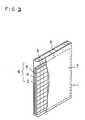
- A conventional sealed lead-acid storage battery is constructed as shown in Fig. 2 which is used as power source of portable apparatus or the like. In Fig. 4, numeral 1 denotes a casing made of a thermoplastic resin and receiving a gorup of
electrodes 6 composed of apositive electrode 2, anegative electrode 3, and aseparator 4. An opening portion of a casing 1 surrounding the periphery of the group of theelectrodes 6 is hermetically sealed, when the opening portion is thermally bonded to a periphery of ametal plate 7 for a battery casing, an inner surface of which metal plate has been already laminated with a polyethylene film or the like. Numeral 5 denotes a pole bar portion, andnumeral 8 denotes a vent valve formed at the casing 1 and having the function of opening the valve with the increment of the inner pressure of the battery. The method for sealing completely thepole bar portion 5 will be described hereinbelow. One method is that an adhesive such as an epoxy resin is filled and hardened. The other method is that a sheet of lead alloy coated previously with the epoxy resin or a polyethylene resin is welded to a protruding portion of the electrode by TIG welding or the like to form a pole bar, and the resulting pole bar is thermally bonded between the casing and the metal plate for a battery casing. - In such a conventional structure, the hardening of adhesive usually requires approximately one hour at 60oC because the adhesive such as the epoxyresin or the like is used for sealing of the
pole bar portion 5. As a result, it is impossible to improve production capacity in producing process. In the method that the sheet of lead alloy coated with the epoxy resin or the polyethylene resin is welded to the protruding portion, it was difficult to construct efficiently assembling line of sealed lead-acid storage battery at a high-speed and low cost, since there was a problem in reliability of welding and cost. - The present invention has been developed in view of the above-mentioned drawbacks and contemplates to provide an improved sealed lead-acid storage battery described hereinbelow. Owing to the fact that a protruding portion of an electrode is coated with an epoxy resin and a polyolefin resin and therefore it is possible to bond thermally the protruding portion with a casing and one surface of metal plate coated with a polyolefin film or the like, it is possible to make an assembling line for assembling the battery with efficiency at high-speed. As a result, the sealed lead-acid storage battery can be made which has a high volumetric efficiency and is of low cost.
- According to the present invention, the sealing structure of the pole bar portion is characterized in the next point described below.
- First, the protruding portion of each of the electrode is directly coated with the epoxy resin and the polyolefin resin, a group of electrodes is thereafter sandwiched between the casing made of a thermoplastic resin and surrounding the periphery of a group of electrodes and metal plate whose inner surface is laminated with a polyolefin film, and then, on thermal bonding of the casing and the metal plates, the protruding portions of electrodes are also thermally bonded to them for sealing the opening, instead of that conventionally, the above-mentioned epoxy resin adhesive is used for adhesion, and a sheet of lead alloy coated with the epoxy resin and the polyolefin resin is welded to the porotruding portion of the electrode, and then, the resulting part is thermally bonded to the casing.
- Since the process and installation for assembling the battery are simplified and it is possible to shorten largely the operation time of opening-sealing process by this structure, the battery can be assembled at a high-speed. As a result, the sealed lead-acid storage battery of low cost, high reliability, and excellent volumetric efficiency can be provided.
- Preferably, the casing of the battery casing and the pressing plate of the cushion are formed integrally, the joint portion of the pressing plate is formed such that the thickness of the joint portion is thinner than that of the pressing plate, thereby being easy to be bent by the function of the hinge, and the pressing plate fitting portion of the opening of the concave portion is provided with a concave portion and a convex portion. As a result, once the pressing plate is fitted, it is difficult to be disengaged.
- By this structure, the operation efficiency is largely improved and the products are stably obtained in quality in comparison with the conventional method. As a result, hereafter, even if sealed lead-acid storage battery is miniaturized, it is possible to design the structure in accordance with such trend.
-
- Fig. 1 is a perspective view of the sealed lead-acid storage battery before assembling of the embodiment of the present invention;
- Fig. 2 is a perspective view showing the structure of the conventional sealed lead-acid storage battery.
- The embodiment of the present invention will be described hereinbelow. Fig. 1 shows a sealed lead-acid storage battery of the present invention, and numeral 1 denotes a casing made of a polyolefin resin such as a polyethylene resin, which casing surrounds a periphery of a group of electrodes. A protruding portion of an
electrode 5a is directly coated with an epoxy resin which is superior in heat resistance and adhesive property, the epoxy resin thereafter is hardened, and then the resulting surface is again coated with a modified-polyethylene solution. The group ofelectrodes 6 comprises apositive electrode 2 and anegative electrode 3 each having a protruding portion coated as described above, and aseparator 4 made of nonwoven fabric mainly composed of glass fiber of diameter less than 5 µm, whichseparator 4 is superior in absorbing power of electrolyte. The group ofelectrodes 6 is received in the casing 1. - As a
metal plate 7 for a battery casing, is used an aluminium plate, a stainless steel plate, or a tinned steel plate. A thermally bondable polyethylene or polyester film is bonded, and especially, a thermally bondable film or sheet including one body with three layers consisting of an ethylene acrilic acid (EAA) layer, a polyethylene terephthalate (PET) layer, and another ethylene acrilic acid (EAA) layer, which film or sheet has been improved in acid resistance and strength on thermal bonding, is laminated to one surface of the metal plate by means of adhesion or bonding by fusion. The group of electrodes is sandwiched between twometal plates 7 with the resin film layer of each of the metal plates being opposed to the group of electrodes, and then the rim of themetal plates 7 and the rim of the opening of the casing 1 are thermally bonded each other. At the casing 1, are provided in advance, a shallow, slender and longconcave portion 18 in which the protruding portion of theelectrodes 5a is fitted on thermal bonding, and avent valve 8 arranged to be opened when the inner pressure of the battery rises above a predetermined value. When themetal plates 7 for the battery casing are thermally bonded to the casing 1, theprotruding portions 5a also are thermally bonded to the casing 1 and thermal bonding film on one side of themetal plates 7. - The separator is impregnated with the electrolyte indispensable to the battery in advance before this thermal bonding.
- Before thermal bonding, an uncoated edge of the protruding portion of the
electrode 5a arranged to be fitted in theconcave portion 18 of the casing 1 made of a resin is spot-welded or the like to a film-removed portion of inner edge portion of themetal plate 7 for battery casing to connect each other electrically, so that the metal plate forbattery casing 7 is used as an external terminal. - According to the present invention as described above, the
protruding portions 5a of the electrodes of the pole bar portions are directly coated with the epoxy resin in advance, and the surfaces coated with the epoxy resin are coated with the polyolefin resin having the property of thermal bonding. Therefore, themetal plates 7 for the battery casing and the pole bar portions can be thermally bonded to the casing 1 surrounding the periphery of the group of the electrodes in the same instant. As a result, the assembling process is simplified and is completed at a high-speed, and the sealed lead-acid storage battery of low cost, high reliability, and high volumetric efficiency can be made in comparison with the conventional method that adhesive is used and the pole bar treated by a resin is welded to the electrode. - According to the present invention described above, the number of parts to be used for the terminal portion decreases thereby reducing cost. Hereafter, the tendency of miniaturization of sealed lead-acid storage battery can be dealt with.
Claims (6)
- A sealed lead-acid storage battery comprising a group of electrodes consisting of a positive electrode, a negative electrode, and a separator is sandwiched between two metal plates laminated with a polyolefin resin film or sheet on one surface of said metal plate such that said polyolefin resin layer of said metal plate faces said group of electrodes, and said group of electrodes is sealed hermetically with a casing made of said polyolefin resin and surrounding a periphery of said group of electrodes and a peripheral rim of said metal plate being thermally bonded, and in that a protruding portion of a positive electrode and a negative electrode is coated with an epoxy resin and again coated with said polyolefin resin on said epoxy resin layer, said resulting protruding portion is sandwiched between said casing and said metal plate having said polyolefin layer so that said group of electrodes is hermetically sealed and said protruding portion is hermetically sealed between said casing and said resin layer surface of said metal plate.
- A sealed lead-acid storage battery as claimed in claim 1, wherein said separator is mainly composed of glass fiber of diameter less than 5 µm.
- A sealed lead-acid storage battery as claimed in claim 1, wherein said polyolefin resin film or sheet provided on one surface of said metal plate includes one body with three layers consisting of an ethylene acrilic acid layer, a polyethylene terephthalate layer, and another ethylene acrilic acid layer.
- A sealed lead-acid storage battery as claimed in claim 1, wherein said metal plate laminated with said film or sheet made of said polyolefin resin on one surface of said metal plate is a tinned steel plate.
- A sealed lead-acid storage battery as claimed in claim 1, wherein said protruding portion of said electrode is welded to a portion of a peripheral rim portion of one surface of said metal plate so that said metal plate is formed to be an external terminal.
- A sealed lead-acid storage battery as claimed in claim 1, wherein a concave portion is formed, for receiving said protruding portion of said electrode, in said casing to be sandwiched bewteen said metal plates and to be thermally bonded.
Applications Claiming Priority (4)
| Application Number | Priority Date | Filing Date | Title |
|---|---|---|---|
| JP62125/86 | 1986-03-19 | ||
| JP61062125A JPS62217559A (en) | 1986-03-19 | 1986-03-19 | Manufacture of sealed lead-acid battery |
| JP62222/86 | 1986-03-20 | ||
| JP61062222A JPS62219461A (en) | 1986-03-20 | 1986-03-20 | Sealed lead-acid battery |
Publications (3)
| Publication Number | Publication Date |
|---|---|
| EP0263881A1 EP0263881A1 (en) | 1988-04-20 |
| EP0263881A4 EP0263881A4 (en) | 1989-02-23 |
| EP0263881B1 true EP0263881B1 (en) | 1992-08-12 |
Family
ID=26403183
Family Applications (1)
| Application Number | Title | Priority Date | Filing Date |
|---|---|---|---|
| EP87901686A Expired - Lifetime EP0263881B1 (en) | 1986-03-19 | 1987-03-16 | Hermetically sealed lead storage battery |
Country Status (4)
| Country | Link |
|---|---|
| US (1) | US4929518A (en) |
| EP (1) | EP0263881B1 (en) |
| DE (1) | DE3781082T2 (en) |
| WO (1) | WO1987005749A1 (en) |
Families Citing this family (16)
| Publication number | Priority date | Publication date | Assignee | Title |
|---|---|---|---|---|
| US5227260A (en) * | 1991-11-04 | 1993-07-13 | Globe-Union, Inc. | Sealed lead acid battery using modular frame construction |
| US5419982A (en) * | 1993-12-06 | 1995-05-30 | Valence Technology, Inc. | Corner tab termination for flat-cell batteries |
| US5976730A (en) * | 1994-05-19 | 1999-11-02 | White Eagle International Technologies, Inc. | Electrical energy generation |
| JPH11288698A (en) * | 1998-03-10 | 1999-10-19 | Samsung Display Devices Co Ltd | Rechargeable battery |
| US6267790B1 (en) * | 1998-03-18 | 2001-07-31 | Ntk Powerdex, Inc. | Treatment of conductive feedthroughs for battery packaging |
| RU2139607C1 (en) * | 1999-02-12 | 1999-10-10 | Закрытое акционерное общество "Интеллект" | Storage cell with maximum size less than 100 mm |
| WO2001037353A1 (en) * | 1999-11-15 | 2001-05-25 | Eveready Battery Company, Inc. | Durable high density power supply |
| US6443999B1 (en) * | 2000-03-16 | 2002-09-03 | The Gillette Company | Lithium cell with heat formed separator |
| KR100502337B1 (en) * | 2002-12-26 | 2005-07-20 | 삼성에스디아이 주식회사 | Lithium secondary battery |
| US20060216595A1 (en) * | 2005-03-22 | 2006-09-28 | Holliday Rex W | Battery assembly having improved lug profile |
| US20080124624A1 (en) * | 2006-10-30 | 2008-05-29 | Ching-Chun Lin | Battery casing |
| TWM311123U (en) * | 2006-11-22 | 2007-05-01 | Dynapack Internat Technology C | Thin-type battery casing |
| TWI366935B (en) * | 2007-10-15 | 2012-06-21 | Asustek Comp Inc | Battery structure |
| DE102009035457A1 (en) * | 2009-07-31 | 2011-02-03 | Daimler Ag | Battery, in particular vehicle battery |
| KR101147208B1 (en) * | 2009-10-16 | 2012-05-29 | 삼성에스디아이 주식회사 | Rechargeable battery, bipolar electrode, and fabricating method rechargeable battery |
| WO2019102863A1 (en) * | 2017-11-21 | 2019-05-31 | 株式会社村田製作所 | Battery case |
Family Cites Families (8)
| Publication number | Priority date | Publication date | Assignee | Title |
|---|---|---|---|---|
| JPS54133336U (en) * | 1978-03-08 | 1979-09-14 | ||
| CH658342A5 (en) * | 1983-01-07 | 1986-10-31 | Sonval S A | GAS-TIGHT PRIMARY BATTERY. |
| JPS59146149A (en) * | 1983-02-07 | 1984-08-21 | Sanyo Electric Co Ltd | Manufacture of lead battery |
| JPS60118867U (en) * | 1984-01-19 | 1985-08-10 | 松下電器産業株式会社 | Sealed battery safety valve device |
| JPS60193257A (en) * | 1984-03-14 | 1985-10-01 | Sanyo Electric Co Ltd | Lead-acid battery |
| US4582767A (en) * | 1984-03-13 | 1986-04-15 | Sanyo Electric Co., Ltd. | Lead storage battery |
| US4556612A (en) * | 1984-12-05 | 1985-12-03 | General Electric Company | Resealable vent valve for a rechargeable battery |
| US4636446A (en) * | 1985-11-15 | 1987-01-13 | Cheng Kwang Storage Battery Co., Ltd. | Stopper structure for storage battery container |
-
1987
- 1987-03-16 US US07/138,458 patent/US4929518A/en not_active Expired - Lifetime
- 1987-03-16 EP EP87901686A patent/EP0263881B1/en not_active Expired - Lifetime
- 1987-03-16 WO PCT/JP1987/000164 patent/WO1987005749A1/en not_active Ceased
- 1987-03-16 DE DE8787901686T patent/DE3781082T2/en not_active Expired - Lifetime
Also Published As
| Publication number | Publication date |
|---|---|
| DE3781082D1 (en) | 1992-09-17 |
| DE3781082T2 (en) | 1992-12-17 |
| EP0263881A1 (en) | 1988-04-20 |
| EP0263881A4 (en) | 1989-02-23 |
| WO1987005749A1 (en) | 1987-09-24 |
| US4929518A (en) | 1990-05-29 |
Similar Documents
| Publication | Publication Date | Title |
|---|---|---|
| EP0263881B1 (en) | Hermetically sealed lead storage battery | |
| EP0164963B1 (en) | Insulating seal for electrochemical cells | |
| KR100708023B1 (en) | Film-packaged electric device and its manufacturing method | |
| JP5346086B2 (en) | Thin film battery | |
| JPH0582020B2 (en) | ||
| EP0484368B1 (en) | A method of closing one end of the case of a sodium/sulphur cell and a sodium/sulphur cell produced by this method | |
| US4904550A (en) | Sealed lead-acid battery | |
| JPH1012200A (en) | Battery | |
| JPH0963550A (en) | Battery | |
| JP4666131B2 (en) | LAMINATE FILM HEAT FUSION METHOD, FILM PACKAGE BATTERY MANUFACTURING METHOD, AND LAMINATE FILM HEAT FUSION DEVICE | |
| JPS58126664A (en) | Electrochemical cell and its sealing method | |
| JP2001052659A (en) | Stacked polymer electrolyte battery | |
| JPH0845795A (en) | Electric double layer capacitor | |
| JPH08287889A (en) | Thin polymer solid electrolyte battery and method of manufacturing the same | |
| JPH0648620B2 (en) | Manufacturing method of assembled sealing plate for organic electrolyte battery | |
| JPS58129745A (en) | Thin enclosed battery | |
| CN216120518U (en) | Battery cover plate and battery | |
| JP3738198B2 (en) | battery | |
| JPS5946755A (en) | Battery | |
| JPH0451938B2 (en) | ||
| JPH0475251A (en) | Battery pack | |
| JP2025121194A (en) | Current collecting terminals and laminated batteries | |
| JPH0729553A (en) | Sealed lead-acid battery | |
| JPS5848772Y2 (en) | flat alkaline battery | |
| JPH0155546B2 (en) |
Legal Events
| Date | Code | Title | Description |
|---|---|---|---|
| PUAI | Public reference made under article 153(3) epc to a published international application that has entered the european phase |
Free format text: ORIGINAL CODE: 0009012 |
|
| 17P | Request for examination filed |
Effective date: 19871117 |
|
| AK | Designated contracting states |
Kind code of ref document: A1 Designated state(s): DE FR GB |
|
| A4 | Supplementary search report drawn up and despatched |
Effective date: 19890223 |
|
| 17Q | First examination report despatched |
Effective date: 19900919 |
|
| GRAA | (expected) grant |
Free format text: ORIGINAL CODE: 0009210 |
|
| AK | Designated contracting states |
Kind code of ref document: B1 Designated state(s): DE FR GB |
|
| REF | Corresponds to: |
Ref document number: 3781082 Country of ref document: DE Date of ref document: 19920917 |
|
| ET | Fr: translation filed | ||
| PLBE | No opposition filed within time limit |
Free format text: ORIGINAL CODE: 0009261 |
|
| STAA | Information on the status of an ep patent application or granted ep patent |
Free format text: STATUS: NO OPPOSITION FILED WITHIN TIME LIMIT |
|
| 26N | No opposition filed | ||
| REG | Reference to a national code |
Ref country code: GB Ref legal event code: 746 Effective date: 19960822 |
|
| REG | Reference to a national code |
Ref country code: GB Ref legal event code: IF02 |
|
| PGFP | Annual fee paid to national office [announced via postgrant information from national office to epo] |
Ref country code: FR Payment date: 20030310 Year of fee payment: 17 |
|
| PGFP | Annual fee paid to national office [announced via postgrant information from national office to epo] |
Ref country code: GB Payment date: 20030312 Year of fee payment: 17 |
|
| PGFP | Annual fee paid to national office [announced via postgrant information from national office to epo] |
Ref country code: DE Payment date: 20030327 Year of fee payment: 17 |
|
| PG25 | Lapsed in a contracting state [announced via postgrant information from national office to epo] |
Ref country code: GB Free format text: LAPSE BECAUSE OF NON-PAYMENT OF DUE FEES Effective date: 20040316 |
|
| PG25 | Lapsed in a contracting state [announced via postgrant information from national office to epo] |
Ref country code: DE Free format text: LAPSE BECAUSE OF NON-PAYMENT OF DUE FEES Effective date: 20041001 |
|
| GBPC | Gb: european patent ceased through non-payment of renewal fee |
Effective date: 20040316 |
|
| PG25 | Lapsed in a contracting state [announced via postgrant information from national office to epo] |
Ref country code: FR Free format text: LAPSE BECAUSE OF NON-PAYMENT OF DUE FEES Effective date: 20041130 |
|
| REG | Reference to a national code |
Ref country code: FR Ref legal event code: ST |