EP0263677A2 - Détendeur à basse pression pour appareil respiratoire et appareil utilisant un tel détendeur - Google Patents
Détendeur à basse pression pour appareil respiratoire et appareil utilisant un tel détendeur Download PDFInfo
- Publication number
- EP0263677A2 EP0263677A2 EP87308841A EP87308841A EP0263677A2 EP 0263677 A2 EP0263677 A2 EP 0263677A2 EP 87308841 A EP87308841 A EP 87308841A EP 87308841 A EP87308841 A EP 87308841A EP 0263677 A2 EP0263677 A2 EP 0263677A2
- Authority
- EP
- European Patent Office
- Prior art keywords
- breathing
- valve
- pressure
- control chamber
- regulator
- Prior art date
- Legal status (The legal status is an assumption and is not a legal conclusion. Google has not performed a legal analysis and makes no representation as to the accuracy of the status listed.)
- Granted
Links
Images


Classifications
-
- A—HUMAN NECESSITIES
- A62—LIFE-SAVING; FIRE-FIGHTING
- A62B—DEVICES, APPARATUS OR METHODS FOR LIFE-SAVING
- A62B9/00—Component parts for respiratory or breathing apparatus
- A62B9/02—Valves
- A62B9/022—Breathing demand regulators
-
- A—HUMAN NECESSITIES
- A62—LIFE-SAVING; FIRE-FIGHTING
- A62B—DEVICES, APPARATUS OR METHODS FOR LIFE-SAVING
- A62B7/00—Respiratory apparatus
- A62B7/14—Respiratory apparatus for high-altitude aircraft
-
- G—PHYSICS
- G05—CONTROLLING; REGULATING
- G05D—SYSTEMS FOR CONTROLLING OR REGULATING NON-ELECTRIC VARIABLES
- G05D16/00—Control of fluid pressure
- G05D16/14—Control of fluid pressure with auxiliary non-electric power
- G05D16/16—Control of fluid pressure with auxiliary non-electric power derived from the controlled fluid
- G05D16/163—Control of fluid pressure with auxiliary non-electric power derived from the controlled fluid using membranes within the main valve
Definitions
- This invention relates to low pressure breathing regulators for use in aircraft breathing gas systems.
- oxygen-enriched air is supplied as breathing gas for an aircrew member by an on-board oxygen generating system (OBOGS) comprising a molecular sieve oxygen generating system (MSOGS) arranged to deliver oxygen-enriched air of desired oxygen concentration value by adsorbing nitrogen from air fed to the system.
- OOGS on-board oxygen generating system
- MSOGS molecular sieve oxygen generating system
- Oxygen-enriched air produced by either system is delivered to an aircrew breathing mask by way of a demand valve breathing regulator.
- a problem was found to exist with respect to demand valve operation in a breathing regulator suitable for accommodating the lower range of oxygen-enriched air pressure available from a MSOGS, particularly at the lower end towards 70 kPa (10 psi).
- a controlled bleed is provided from the demand-pressure sensing chamber to the breathing-pressure control chamber, in the particular embodiment of EP-A-0,078,644 the bleed being by way of an orifice in the diaphragm, and pressure in the breathing-pressure control chamber is controlled by the aneroid valve which allows gas to pass from the breathing-pressure control chamber to the cabin-pressure sensing chamber from which it is discharged to the cabin by way of an outlet in the cabin-pressure sensing chamber.
- the aneroid valve expands to increasingly restrict the flow of gas from the breathing-pressure control chamber. This causes the pressure in the breathing-pressure control chamber to increase thereby increasing the pressure of the breathing gas at the regulator outlet and hence in a breathing mask connected to the regulator outlet. This ensures that breathing gas is supplied at a pressure greater than aircraft cabin ambient pressure so that the minimum critical oxygen pressure is maintained in the lungs of the aircrew member breathing the gas. This is referred to in the art as positive pressure breathing.
- a breathing regulator suitable for use with breathing gas delivered by a MSOGS and which will provide positive pressure breathing to aid in protecting an aircrew member against the effects of increasing G loads experienced during highly accelerative manoeuvres of his aircraft irrespective of the altitude at which the aircraft is operating.
- the present invention provides a breathing regulator for controlling delivery of breathing air in accordance with breathing demands of an aircrew member, comprising a regulator body having an inlet for receiving a flow of breathing air and an outlet for delivering breathing air to a face mask worn by an aircraft aircrew member, a demand valve for controlling flow of said breathing air through the regulator body from the inlet to the outlet, a demand-pressure sensing chamber having communication with the outlet, a breathing-pressure control chamber having communication with aircraft cabin atmosphere ambient of the regulator, a diaphragm dividing the demand-pressure sensing chamber from the breathing-pressure control chamber and having connection with the demand valve for opening movement of the demand valve in response to breathing demand sensed in the demand-pressure sensing chamber, means for supplying a bleed of breathing air to the breathing-pressure control chamber, and means for restricting flow of breathing air from the breathing-pressure control chamber to ambient, characterised in that the flow restricting means comprise valve means for restricting flow from the breathing-pressure control chamber in response to signals received from a G-sensitive
- a breathing regulator in accordance with the present invention is particularly, although not exclusively, suited for use in conjunction with an aircraft on-board oxygen generating system for supplying oxygen-enriched air for breathing by aircrew.
- the present invention provides an aircraft on-board oxygen generating system (OBOGS) for supplying oxygen-enriched air for breathing by an aircrew member, including a molecular sieve oxygen generating system (MSOGS), a breathing regulator having an inlet connected for receiving a flow of oxygen-enriched air of required composition delivered by the MSOGS and an outlet for delivering oxygen-enriched breathing air to a face mask worn by the aircrew member, the breathing regulator further comprising a demand valve for controlling flow of oxygen-enriched air through the regulator from the inlet to the outlet in response to breathing demands of the aircrew member, said breathing demands being sensed in a demand-pressure sensing chamber within the regulator and divided from a breathing-pressure control chamber by a diaphragm having connection with the demand valve for movement of the demand valve to an open position in response to breathing demands, means for passing a bleed of oxygen-enriched air to the breathing-pressure control chamber to build up a control pressure therein and means for communicating the breathing-pressure control chamber with aircraft cabin pressure, whereby oxygen
- the control pressure in the breathing-pressure control chamber may be destroyed causing the regulator to become inoperative so that the aircrew member is starved of breathing air until pressure in the breathing-pressure control chamber rebuilds.
- one embodiment of the present invention further provides means for by-passing said valve means whereby a metered flow of pressurised air from the G sensitive valve may flow to the breathing-pressure control chamber to maintain control pressure therein under high or rapidly changing G load conditions.
- the by-pass means may be embodied in the valve means and may comprise a ball non-return valve or a flap non-return valve arranged for closing a passageway through a valve stem and valve head of said valve means.
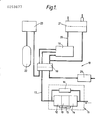
- oxygen-enriched air for breathing by an aircrew member is supplied by a molecular sieve oxygen generating system (MSOGS) 11 comprising three molecular sieve beds 12, 13, 14 suitably interconnected and controlled by an electronic control unit 15 and oxygen concentration sensor 16 such as is disclosed in EP-A-0,129,304.
- the MSOGS receives a bleed of air from an engine (not shown) of an aircraft in which the OBOGS is installed and outputs oxygen-enriched air which is delivered by a supply line 17, and by way of a services connector 18, to a breathing regulator 19.
- the breathing regulator 19 is connected by a delivery line 20 to a personal equipment connector 21 which provides a single point attachment for all services between an aircraft seat (not shown) and the aircrew member.
- the OBOGS also includes a standby oxygen cylinder 22 containing 100% oxygen and a control panel 23 providing indications and switching/selection mechanisms required by the crew member, including safety pressure selection, press-to-test, standby oxygen manual selection, automatic selection of 100% oxygen in the event of cabin decompression at high altitude and dolls-eye blinker breathing indication.
- An electro-pneumo-mechanical G sensitive valve 24, hereinafter referred to as an anti-G valve, is attached to the aircraft structure (not shown) and provides a pneumatic signal for inflation of a lower garment, or G-suit (not shown) worn by the aircrew member for protection against G loads as is well known.
- the pneumatic signal from the anti-G valve 24 is also fed to a valve (not shown in Figure 1) controlling pressure in a breathing-pressure control chamber of the breathing regulator 19 by throttling discharge of gas from that chamber to aircraft cabin atmosphere.
- Pressure in the breathing-pressure control chamber is further controlled, but not necessarily simultaneously, at high altitudes, say above 12,000 metres (40,000 feet) by an aneroid capsule-mounted valve which also acts to throttle escape of gas from the breathing-pressure control chamber to aircraft cabin atmosphere.
- PPB positive pressure breathing
- a demand valve breathing regulator in accordance with an embodiment of the present invention, and suitable for use in the OBOGS hereinbefore described with reference to Figure 1, will now be described with reference to Figures 2, 3 and 4.
- a regulator 30 comprises a body having an inlet 31 for receiving oxygen-enriched air from a MSOGS and an outlet 32 for delivering the oxygen-enriched air to a face mask (not shown) of an aircrew member.
- Flow of oxygen-enriched air through the regulator 30 is controlled by a demand valve arrangement including a demand valve 33 having a valve head 34 supported by a spindle 35 from a spool 36 which slides in a bore 37 in the regulator body.
- the valve head 34 is urged towards a closing position by a compression spring 38 acting between the valve head and a threaded adjuster 39.
- the opposed surface areas of the valve head 34 and the spool 36 are equal so that the valve 33 is balanced by the pressure of the oxygen-enriched air entering the inlet 31.
- the spool 36 is provided on its circumferential surface with grooves in the manner of a labyrinth seal 40 and a second spindle 41 projects from the end surface of the spool opposite the end surface from which the spindle 35 projects.
- the end of the spindle 41 contacts a valve operating lever 42 housed in a demand-pressure sensing chamber 43 and arranged to rock about one of its ends 44.
- the other end 45 of the lever 42 bears on the centre of a diaphragm 46 which divides the demand-pressure sensing chamber 43 from a breathing-pressure control chamber 47.
- the demand-pressure sensing chamber 43 is arranged to be open to pressure at the outlet 32 whilst the breathing-pressure control chamber 47 is arranged to receive a bleed of oxygen-enriched air.
- the bleed of oxygen-enriched air is delivered by way of a passageway 48 which connects between the closed end of the bore 37 in which the spool 36 slides and the breathing-pressure control chamber 47, and is supplied by leakage of oxygen-enriched air past the labyrinth seal 40 of the spool 36; however, the bleed could be supplied in other manner such as, for example, by an orifice in the diaphragm 46.
- the breathing-pressure control chamber is arranged to be open to aircraft cabin pressure by way of a passageway 49, a chamber 50, a passageway 51, a chamber 52, a passageway 53 and an outlet 54.
- the chamber 50 houses a valve head 55 carried by an aneroid capsule 56 and adapted for closing the entry of the passageway 49 into the chamber 50 whereby the pressure in the breathing-pressure control chamber 47 may be controlled in relation to cabin altitude.
- the passageway 49 is branched and connects with a pressure-relief valve 57 that is arranged to open when a predetermined maximum pressure occurs in the breathing-pressure control chamber 47.
- the chamber 52 houses a valve 58 which is connected by way of a conduit 59 for receiving pneumatic signals output by an anti-G valve (not shown in Figure 2), and whereby the valve 58 is pneumatically controlled to throttle passage of oxygen-enriched air to chamber 52 from the breathing-pressure control chamber by way of passageway 49, chamber 50, and passageway 53.
- Oxygen-enriched air passing to chamber 52 escapes to ambient by way of passageway 53 and outlet 54, the outlet 54 being closable for test purposes by a press-to-test member 60 which may be solenoid operated.
- the passageway 53 also connects with cabin by way of a pressure relief valve 61.
- Pressure in the breathing-pressure control chamber 47 is sensed, by way of a passageway 62 branching from passageway 49, on one side of a diaphragm 63 and together with a spring 64 acts to urge a valve head 65 carried by the diaphragm 63 towards closing a secondary outlet 66 from the outlet 32 by which oxygen-enriched air in the outlet 32 may be vented to the aircraft cabin.
- the valve head 65 is arranged to open when the pressure in the outlet 32 is, say, 125 Pa (0.5 inches/WG) above that in the breathing-pressure control chamber 47.
- the diaphragm 46 dividing the demand-pressure sensing chamber 43 from the breathing-pressure control chamber 47 is backed by a spring 67 located in the control chamber 47.
- the spring 67 acts on the diaphragm 46 through a plate 68 which in an operational condition of the regulator contacts the diaphragm and through lever 42 urges the demand valve 33 towards an open position against the action of spring 38.
- Spring 38 is adjusted by the adjuster 39 such that when the diaphragm 46 is in a null position, the valve head 34 of demand valve 33 is held off its seat sufficiently to maintain a positive pressure (safety pressure) of 250 Pa (1 inch/WG) in the outlet 32.
- spring 67 may be negated by operation of a solenoid 69 which causes a pivotal lever 70 connected with a central spindle 71 projecting from the plate 68 to lift the plate out of contact with the diaphragm 46.
- the demand valve 33 responds by movement of diaphragm 46 to inhalatory and exhalatory phases of breathing by an aircrew member wearing a face mask connected with the outlet 32 of the regulator. Breathing cycle pressure exists in the outlet 32 and demand-pressure sensing chamber 43, being sensed by the diaphragm 46.
- the diaphragm 46 is drawn in a downward direction, as viewed in Figure 2, during inhalation so as to deflect the lever 42 and cause it to move the demand valve 33 to the right as viewed in Figure 2, from the slightly preset open position, that gives the safety pressure condition, to a full flow state giving rapid maximum flow response feeding oxygen-enriched air to the outlet 32. Exhalation causes a cessation of flow and consequent pressure build-up in the outlet and the demand-pressure sensing chamber 43 to an extent where the diaphragm 46 is returned to the null position until the cycle is repeated.
- Oxygen-enriched air bleeds to the breathing-pressure control chamber 47 by way of the passageway 48 and escapes therefrom to aircraft cabin by way of passageway 49, chamber 50, passageway 51, chamber 52, passageway 53 and outlet 54.
- the anti-G valve signals the valve 58 in chamber 52 to move towards further restricting passage of oxygen-enriched air into chamber 52 by way of passageway 51 so that the pressure in the breathing-pressure control chamber increases and, consequently, the pressure of oxygen-enriched air in outlet 32 is also increased, as previously described for operation of the aneroid valve in chamber 50, so as to be positive with respect to aircraft cabin ambient pressure in assisting the breathing effort of the aircrew member under the effects of increasing G load.
- valve 58 in chamber 52 may decrease restriction of passageway 51 so quickly as to allow oxygen-enriched air to flow to the aircraft cabin from the breathing-pressure control chamber 47 at a rate so much in excess of the flow into chamber 47 as to cause the diaphragm 46 to collapse upwardly, as viewed in Figure 2, towards the top of the chamber 47. This will render the regulator inoperative until pressure in the chamber 47 rebuilds and during that period the aircrew member will be starved of oxygen-enriched air for breathing.
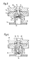
- valve 58 in chamber 52 is of one or other of the valve constructions shown in Figures 3 and 4, so that a flow of air from the anti-G valve is allowed to by-pass the valve 58 to assist in rebuilding pressure in the breathing-pressure control chamber at the required rate to maintain satisfactory operation of the regulator.
- the valve 58 comprises a hollow valve stem 72 having a valve head 73 at one end thereof.
- the valve 58 is carried by a diaphragm 74 which extends across an inlet 75 into the body of the regulator 30 and is trapped between the regulator body and a flange 76 of a bush member 77 in which the valve stem 72 slides.
- a non-return valve assembly 78 is housed internally of a bore 79 in the valve stem 72 and comprises a cylindrical body 80 projecting a threaded end 81 through an end wall of the valve stem and the diaphragm 74 for attachment thereto by a nut 82.
- the cylindrical body 80 has a by-pass bore 83 extending therethrough.
- the by-pass bore is of larger diameter at its end which opens internally of the bore 79 for receiving a non-return ball valve member 84 that is retained within the bore 83 by a cross-pin 85.
- the pneumatic signal from the anti-G valve through the inlet 75 will act on the diaphragm 74 to force the valve head 73 to throttle the escape of oxygen-enriched air from the breathing-pressure control chamber of the regulator so building up pressure in the breathing-pressure control chamber.
- the pressure so generated will be a function of the area ratio of the area of the valve head 73 and the area of the valve stem 72, and the pressure applied at the inlet 75.
- air from the anti-G valve will flow through the bore in the cylindrical body 80 into the breathing-pressure control chamber to supplement the oxygen-enriched air flowing into that chamber through passageway 48. This supplemental airflow ensures that the control pressure in the breathing-pressure control chamber is maintained during all excursions of the diaphragm 46.
- Another function of the regulator is to provide a pressure in the mask to check mask fit. This pressure is generated by the press-to-test member 60 closing outlet 54 thereby causing pressure to build up in the breathing-pressure control chamber. This function is checked before flight when there is no flow from the anti-G valve and to prevent loss of oxygen-enriched air from the breathing-pressure control chamber the non-return ball valve member 84 is included in the by-pass bore 83 of the cylindrical body 80.
- valve 58 there shown is of similar construction to that shown in Figure 3 but with the exception of the non-return valve assembly 86 which is of flap valve type.
- the non-return valve assembly 86 comprises a body member 87 housed within the bore 79 of the valve stem 72 and projects a threaded end 88 through the end wall of the valve stem 72 and diaphragm 74 for attachment thereto by a nut 89.
- a bore 90 enters the body member 87 at that end which faces the inlet 75 and is turned to exit the body member 87 at a location on its side surface intermediate its ends.
- the exit end of the bore 90 is closable by an elastomeric flap valve 91 which is secured to the body member by a screw 92.
- valve 58 Operation of the valve 58 together with its non-return valve assembly 86 is similar to that hereinbefore described for the valve 58 and non-return valve assembly 78 shown in Figure 3.
- valve means such as the valve 58 in the embodiment of Figure 2
- receiving pneumatic signals from the G sensitive valve may be by-passed in other ways, one such example being shown in Figure 5.
- a by-pass conduit 100 is taken from conduit 59 and joined into the regulator body to communicate with passageway 51 on the breathing-pressure control chamber 47 side of the valve 58 thereby by-passing the valve.
- the conduit 100 incorporates a restrictor orifice 101 suitable for giving the required by-pass flow from the anti-G valve to the breathingpressure control chamber, and a non-return valve 102 for purposes previously described.
- the breathing regulator has been particularly described with reference to use with an OBOGS in which it receives oxygen-enriched air from a MSOGS, it may also be used in other aircrew breathing systems such as, for example, a system in which gaseous oxygen is provided by a liquid oxygen system.
Applications Claiming Priority (2)
| Application Number | Priority Date | Filing Date | Title |
|---|---|---|---|
| GB868624230A GB8624230D0 (en) | 1986-10-09 | 1986-10-09 | Aircrew breathing systems |
| GB8624230 | 1986-10-09 |
Publications (3)
| Publication Number | Publication Date |
|---|---|
| EP0263677A2 true EP0263677A2 (fr) | 1988-04-13 |
| EP0263677A3 EP0263677A3 (en) | 1989-05-10 |
| EP0263677B1 EP0263677B1 (fr) | 1992-01-29 |
Family
ID=10605487
Family Applications (1)
| Application Number | Title | Priority Date | Filing Date |
|---|---|---|---|
| EP87308841A Expired - Lifetime EP0263677B1 (fr) | 1986-10-09 | 1987-10-05 | Détendeur à basse pression pour appareil respiratoire et appareil utilisant un tel détendeur |
Country Status (7)
| Country | Link |
|---|---|
| US (1) | US4858606A (fr) |
| EP (1) | EP0263677B1 (fr) |
| CA (1) | CA1281252C (fr) |
| DE (1) | DE3776480D1 (fr) |
| ES (1) | ES2028878T3 (fr) |
| GB (1) | GB8624230D0 (fr) |
| IN (1) | IN167287B (fr) |
Cited By (9)
| Publication number | Priority date | Publication date | Assignee | Title |
|---|---|---|---|---|
| US4960119A (en) * | 1988-05-31 | 1990-10-02 | Normalair-Garrett (Holdings) Limited | Aircraft aircrew life support systems |
| EP0419183A1 (fr) * | 1989-09-21 | 1991-03-27 | Normalair-Garrett (Holdings) Limited | Appareil de survie pour équipage d'aéronef |
| US5036846A (en) * | 1988-02-26 | 1991-08-06 | Puritan-Bennett Corporation | Crew oxygen mask with pneumatic comfort adjustment |
| EP0448258A1 (fr) * | 1990-03-13 | 1991-09-25 | Normalair-Garrett (Holdings) Limited | Appareil de survie pour équipage d'aéronef |
| EP0492804A1 (fr) * | 1990-12-22 | 1992-07-01 | Normalair-Garrett (Holdings) Limited | Régulateur de gaz respiratoire pour équipage d'aéronef |
| US5314402A (en) * | 1990-06-19 | 1994-05-24 | Normalair-Garrett (Holdings) Limited | Aircraft aircrew life support systems |
| US5460175A (en) * | 1992-11-26 | 1995-10-24 | Normalair-Garrett (Holdings) Limited | Air-oxygen mixture controllers for breathing demand regulators |
| US6039045A (en) * | 1987-04-22 | 2000-03-21 | Intertechnique | Head harness for respiratory mask |
| WO2024023421A1 (fr) | 2022-07-27 | 2024-02-01 | Safran Aerosystems | Système respiratoire, notamment pour un aéronef |
Families Citing this family (45)
| Publication number | Priority date | Publication date | Assignee | Title |
|---|---|---|---|---|
| DE3840058A1 (de) * | 1988-11-28 | 1990-05-31 | Auergesellschaft Gmbh | Lungengesteuertes ventil |
| US5000174A (en) * | 1989-10-03 | 1991-03-19 | Cairns & Brother Inc. | Positive pressure breathing assembly and demand regulator therefor |
| US5238008A (en) * | 1991-02-07 | 1993-08-24 | Rockwell International Corporation | Inflatable bladder system for monitoring lung pressure |
| US5170814A (en) * | 1992-02-18 | 1992-12-15 | Litton Systems, Inc. | High altitude G-valve |
| GB9208481D0 (en) * | 1992-04-16 | 1992-06-03 | Normalair Garrett Ltd | Breathing demand regulators |
| US5645055A (en) * | 1992-08-12 | 1997-07-08 | Conax Florida Corporation | Oxygen breathing controller |
| US5701889A (en) * | 1992-08-12 | 1997-12-30 | Conax Florida Corporation | Oxygen breathing controller having a G-sensor |
| US5348001A (en) * | 1992-08-12 | 1994-09-20 | American Safety Flight Systems, Inc. | Oxygen breathing controls |
| US5537994A (en) | 1994-06-03 | 1996-07-23 | Thornton; W. Keith | Combination face mask and dental device for improved breathing during sleep |
| US5983892A (en) | 1994-06-03 | 1999-11-16 | Thornton; W. Keith | Device for improving breathing |
| US5881725A (en) * | 1997-08-19 | 1999-03-16 | Victor Equipment Company | Pneumatic oxygen conserver |
| US7360822B2 (en) * | 1998-02-04 | 2008-04-22 | Oakwood Energy Management, Inc. | Modular energy absorber and method for configuring same |
| US6679967B1 (en) | 1998-02-04 | 2004-01-20 | Oakwood Energy Management, Inc. | Method for making a modular energy-absorbing assembly |
| US6752450B2 (en) * | 1998-02-04 | 2004-06-22 | Oakwood Energy Management, Inc. | Formed energy absorber |
| US6682128B2 (en) * | 1998-02-04 | 2004-01-27 | Oakwood Energy Management, Inc. | Composite energy absorber |
| US6247926B1 (en) | 2000-01-17 | 2001-06-19 | W. Keith Thornton | Oral appliance having a bonding layer and methods for fitting and relining same |
| US6405729B1 (en) | 2000-04-05 | 2002-06-18 | W. Keith Thornton | Oral appliance for improving breathing and method of constructing same |
| US6571798B1 (en) | 2000-04-05 | 2003-06-03 | W. Keith Thornton | Device for improving breathing and method of constructing same |
| US6464924B1 (en) | 2000-04-05 | 2002-10-15 | W. Keith Thornton | Method of forming a custom mask using an impression mask |
| US6364161B1 (en) | 2000-09-27 | 2002-04-02 | Victor Equipment Company | Oxygen conserver |
| US6619285B2 (en) * | 2001-06-13 | 2003-09-16 | Albert D. Hawkins, Jr. | Ambient air breathing device |
| US20030165664A1 (en) * | 2002-03-01 | 2003-09-04 | Oakwood Custom Coating, Inc. | Method of making a composite panel and article made thereby |
| EP1501458B1 (fr) | 2002-05-01 | 2007-08-08 | Keith W. Thornton | Dispositif d'amelioration de la respiration d'un utilisateur |
| US6857428B2 (en) | 2002-10-24 | 2005-02-22 | W. Keith Thornton | Custom fitted mask and method of forming same |
| US7341072B2 (en) * | 2003-05-02 | 2008-03-11 | Carleton Technologies, Inc. | Oxygen supply system having a central flow control unit |
| US7243650B2 (en) | 2004-07-12 | 2007-07-17 | Thornton W Keith | Custom fitted mask configured for coupling to an external gas supply system and method of forming same |
| US7909035B2 (en) * | 2005-07-11 | 2011-03-22 | Airway Technologies, Llc | Multi-chamber mask and method of forming the same |
| US8316858B2 (en) | 2006-04-06 | 2012-11-27 | Airway Technologies, Llc | System for coupling an oral appliance to a medical mask |
| US8236216B2 (en) | 2006-07-06 | 2012-08-07 | Airway Technologies, Llc | System and method for forming a custom medical mask using an orientation device |
| US8874251B2 (en) | 2006-07-06 | 2014-10-28 | Airway Technologies, Llc | System and method for forming a custom medical mask from a three-dimensional electronic model |
| US7992558B2 (en) * | 2006-09-11 | 2011-08-09 | Airway Technologies Llc | Stability medical mask |
| US8020276B2 (en) | 2006-11-30 | 2011-09-20 | Airway Technologies, Llc | System and method for custom-orienting a medical mask to an oral appliance |
| CN101932363B (zh) * | 2007-11-21 | 2012-05-23 | 联合技术公司 | 能降低氧气消耗量的呼吸面罩 |
| US8607796B2 (en) | 2009-02-27 | 2013-12-17 | Airway Technologies, Llc | Apparatus and method for coupling an oral appliance to a gas delivery device |
| US8726424B2 (en) | 2010-06-03 | 2014-05-20 | Intellectual Property Holdings, Llc | Energy management structure |
| WO2012138459A1 (fr) | 2011-04-05 | 2012-10-11 | Airway Technologies, Llc | Appareil oral pour le traitement de troubles particuliers associés au sommeil |
| US9516910B2 (en) | 2011-07-01 | 2016-12-13 | Intellectual Property Holdings, Llc | Helmet impact liner system |
| USD679058S1 (en) | 2011-07-01 | 2013-03-26 | Intellectual Property Holdings, Llc | Helmet liner |
| US9016278B2 (en) * | 2011-07-25 | 2015-04-28 | Zodiac Aerotechnics | Regulation valve for a life support system |
| USD683079S1 (en) | 2011-10-10 | 2013-05-21 | Intellectual Property Holdings, Llc | Helmet liner |
| US9320311B2 (en) | 2012-05-02 | 2016-04-26 | Intellectual Property Holdings, Llc | Helmet impact liner system |
| US9894953B2 (en) | 2012-10-04 | 2018-02-20 | Intellectual Property Holdings, Llc | Helmet retention system |
| USD733972S1 (en) | 2013-09-12 | 2015-07-07 | Intellectual Property Holdings, Llc | Helmet |
| WO2015065902A1 (fr) | 2013-10-28 | 2015-05-07 | Intellectual Property Holdings, Llc | Système de retenue de casque |
| CN106334280B (zh) * | 2015-07-15 | 2019-01-15 | 梅思安(苏州)安全设备研发有限公司 | 压强调节器组件 |
Citations (8)
| Publication number | Priority date | Publication date | Assignee | Title |
|---|---|---|---|---|
| GB1430383A (en) * | 1972-03-23 | 1976-03-31 | Normalair Garrett Ltd | Gas delivery regulators |
| DE2905401A1 (de) * | 1978-02-13 | 1979-08-23 | Max Isaacson | Bedarfs-einatmungsventil |
| EP0050052A2 (fr) * | 1980-09-22 | 1982-04-21 | Litton Systems, Inc. | Régulateur d'oxygène automatique adapté pour l'utilisation dans des environs toxiques |
| DE3109658A1 (de) * | 1981-03-13 | 1982-10-28 | Drägerwerk AG, 2400 Lübeck | Elektrisch steuerbares atemschutzgeraet nach dem kreislaufprinzip |
| EP0078644A2 (fr) * | 1981-10-30 | 1983-05-11 | Normalair-Garrett (Holdings) Limited | Régulateur de refoulement de gaz respiratoir |
| EP0129304A2 (fr) * | 1983-06-15 | 1984-12-27 | Normalair-Garrett (Holdings) Limited | Système de séparation des gaz du type tamis moléculaire |
| GB2144335A (en) * | 1983-08-03 | 1985-03-06 | Normalair Garrett | Gas flow controllers for aircraft |
| DE3401383A1 (de) * | 1984-01-17 | 1985-07-25 | Drägerwerk AG, 2400 Lübeck | Atemschutzmaske mit ueberdruck im maskeninnenraum |
Family Cites Families (8)
| Publication number | Priority date | Publication date | Assignee | Title |
|---|---|---|---|---|
| US2552595A (en) * | 1948-09-21 | 1951-05-15 | Seeler Henry | Oxygen demand breathing system, including means for automatic altitude regulation |
| US3545465A (en) * | 1967-11-29 | 1970-12-08 | Vapor Corp | Pressure regulator |
| FR2455765A1 (fr) * | 1979-05-02 | 1980-11-28 | Intertechnique Sa | Dispositif regulateur d'alimentation en gaz d'un organe recepteur |
| US4619255A (en) * | 1981-11-16 | 1986-10-28 | East/West Industries, Inc. | Oxygen supply system |
| US4499914A (en) * | 1983-04-14 | 1985-02-19 | Litton Systems, Inc. | Selector valve for an aircraft on board oxygen generation system with high pressure oxygen backup |
| US4651728A (en) * | 1984-09-28 | 1987-03-24 | The Boeing Company | Breathing system for high altitude aircraft |
| DE3672510D1 (de) * | 1985-02-22 | 1990-08-16 | Normalair Garrett Ltd | Pneumatischer partialdrucksensor. |
| US4638791A (en) * | 1985-07-22 | 1987-01-27 | The Boeing Company | Apparatus and methods for providing rapid protection from accelerative forces experienced by aircraft crew members |
-
1986
- 1986-10-09 GB GB868624230A patent/GB8624230D0/en active Pending
-
1987
- 1987-10-05 ES ES198787308841T patent/ES2028878T3/es not_active Expired - Lifetime
- 1987-10-05 DE DE8787308841T patent/DE3776480D1/de not_active Expired - Lifetime
- 1987-10-05 EP EP87308841A patent/EP0263677B1/fr not_active Expired - Lifetime
- 1987-10-06 US US07/104,888 patent/US4858606A/en not_active Expired - Fee Related
- 1987-10-07 CA CA000548821A patent/CA1281252C/fr not_active Expired - Fee Related
- 1987-10-08 IN IN725/MAS/87A patent/IN167287B/en unknown
Patent Citations (8)
| Publication number | Priority date | Publication date | Assignee | Title |
|---|---|---|---|---|
| GB1430383A (en) * | 1972-03-23 | 1976-03-31 | Normalair Garrett Ltd | Gas delivery regulators |
| DE2905401A1 (de) * | 1978-02-13 | 1979-08-23 | Max Isaacson | Bedarfs-einatmungsventil |
| EP0050052A2 (fr) * | 1980-09-22 | 1982-04-21 | Litton Systems, Inc. | Régulateur d'oxygène automatique adapté pour l'utilisation dans des environs toxiques |
| DE3109658A1 (de) * | 1981-03-13 | 1982-10-28 | Drägerwerk AG, 2400 Lübeck | Elektrisch steuerbares atemschutzgeraet nach dem kreislaufprinzip |
| EP0078644A2 (fr) * | 1981-10-30 | 1983-05-11 | Normalair-Garrett (Holdings) Limited | Régulateur de refoulement de gaz respiratoir |
| EP0129304A2 (fr) * | 1983-06-15 | 1984-12-27 | Normalair-Garrett (Holdings) Limited | Système de séparation des gaz du type tamis moléculaire |
| GB2144335A (en) * | 1983-08-03 | 1985-03-06 | Normalair Garrett | Gas flow controllers for aircraft |
| DE3401383A1 (de) * | 1984-01-17 | 1985-07-25 | Drägerwerk AG, 2400 Lübeck | Atemschutzmaske mit ueberdruck im maskeninnenraum |
Cited By (11)
| Publication number | Priority date | Publication date | Assignee | Title |
|---|---|---|---|---|
| US6039045A (en) * | 1987-04-22 | 2000-03-21 | Intertechnique | Head harness for respiratory mask |
| US5036846A (en) * | 1988-02-26 | 1991-08-06 | Puritan-Bennett Corporation | Crew oxygen mask with pneumatic comfort adjustment |
| US4960119A (en) * | 1988-05-31 | 1990-10-02 | Normalair-Garrett (Holdings) Limited | Aircraft aircrew life support systems |
| EP0419183A1 (fr) * | 1989-09-21 | 1991-03-27 | Normalair-Garrett (Holdings) Limited | Appareil de survie pour équipage d'aéronef |
| US5199426A (en) * | 1989-09-21 | 1993-04-06 | Normalair-Garrett Holdings, Ltd. | Aircraft aircrew g-responsive valve system for controlling breathing gas and suit-inflation |
| EP0448258A1 (fr) * | 1990-03-13 | 1991-09-25 | Normalair-Garrett (Holdings) Limited | Appareil de survie pour équipage d'aéronef |
| US5314402A (en) * | 1990-06-19 | 1994-05-24 | Normalair-Garrett (Holdings) Limited | Aircraft aircrew life support systems |
| EP0492804A1 (fr) * | 1990-12-22 | 1992-07-01 | Normalair-Garrett (Holdings) Limited | Régulateur de gaz respiratoire pour équipage d'aéronef |
| US5460175A (en) * | 1992-11-26 | 1995-10-24 | Normalair-Garrett (Holdings) Limited | Air-oxygen mixture controllers for breathing demand regulators |
| WO2024023421A1 (fr) | 2022-07-27 | 2024-02-01 | Safran Aerosystems | Système respiratoire, notamment pour un aéronef |
| FR3138322A1 (fr) | 2022-07-27 | 2024-02-02 | Safran Aerosystems | Système respiratoire, notamment pour un aéronef |
Also Published As
| Publication number | Publication date |
|---|---|
| EP0263677B1 (fr) | 1992-01-29 |
| GB8624230D0 (en) | 1987-02-04 |
| IN167287B (fr) | 1990-09-29 |
| EP0263677A3 (en) | 1989-05-10 |
| DE3776480D1 (de) | 1992-03-12 |
| ES2028878T3 (es) | 1992-07-16 |
| US4858606A (en) | 1989-08-22 |
| CA1281252C (fr) | 1991-03-12 |
Similar Documents
| Publication | Publication Date | Title |
|---|---|---|
| EP0263677B1 (fr) | Détendeur à basse pression pour appareil respiratoire et appareil utilisant un tel détendeur | |
| US5701889A (en) | Oxygen breathing controller having a G-sensor | |
| US4336590A (en) | Devices for controlling gas flows | |
| CA1297377C (fr) | Systeme de survie pour l'equipage des avions | |
| EP0419183B1 (fr) | Appareil de survie pour équipage d'aéronef | |
| US4230097A (en) | Breathing and acceleration protection apparatus for aircraft crew members | |
| US5460175A (en) | Air-oxygen mixture controllers for breathing demand regulators | |
| US4148311A (en) | Gas mixing apparatus | |
| CA2648974C (fr) | Systeme de distribution d'oxygene dans un aeronef | |
| US4856507A (en) | Two main piloted valves demand regulator for aviators | |
| US4240419A (en) | Breathable gas delivery regulators | |
| EP2089112B1 (fr) | Circuit d'alimentation en gaz respiratoire destiné à alimenter en oxygène les membres d'équipage et les passagers d'un aéronef | |
| US3672384A (en) | Breathing gas regulator for aviators | |
| US5247926A (en) | Aircrew breathing gas regulators | |
| US5351682A (en) | Breathing demand regulations | |
| WO2008010015A1 (fr) | Circuit d'alimentation en gaz respiratoire destiné à fournir de l'oxygène aux membres d'équipage et aux passagers | |
| US3103927A (en) | Pressure control systems | |
| US5314402A (en) | Aircraft aircrew life support systems | |
| EP0448258B1 (fr) | Appareil de survie pour équipage d'aéronef | |
| US20040216742A1 (en) | Oxygen supply system having a central flow control unit | |
| EP0078644B1 (fr) | Régulateur de refoulement de gaz respiratoir |
Legal Events
| Date | Code | Title | Description |
|---|---|---|---|
| PUAI | Public reference made under article 153(3) epc to a published international application that has entered the european phase |
Free format text: ORIGINAL CODE: 0009012 |
|
| AK | Designated contracting states |
Kind code of ref document: A2 Designated state(s): DE ES GB IT |
|
| PUAL | Search report despatched |
Free format text: ORIGINAL CODE: 0009013 |
|
| AK | Designated contracting states |
Kind code of ref document: A3 Designated state(s): DE ES GB IT |
|
| 17P | Request for examination filed |
Effective date: 19890511 |
|
| 17Q | First examination report despatched |
Effective date: 19910104 |
|
| ITF | It: translation for a ep patent filed |
Owner name: BARZANO' E ZANARDO ROMA S.P.A. |
|
| GRAA | (expected) grant |
Free format text: ORIGINAL CODE: 0009210 |
|
| AK | Designated contracting states |
Kind code of ref document: B1 Designated state(s): DE ES GB IT |
|
| REF | Corresponds to: |
Ref document number: 3776480 Country of ref document: DE Date of ref document: 19920312 |
|
| REG | Reference to a national code |
Ref country code: ES Ref legal event code: FG2A Ref document number: 2028878 Country of ref document: ES Kind code of ref document: T3 |
|
| PLBE | No opposition filed within time limit |
Free format text: ORIGINAL CODE: 0009261 |
|
| STAA | Information on the status of an ep patent application or granted ep patent |
Free format text: STATUS: NO OPPOSITION FILED WITHIN TIME LIMIT |
|
| 26N | No opposition filed | ||
| PGFP | Annual fee paid to national office [announced via postgrant information from national office to epo] |
Ref country code: ES Payment date: 20001025 Year of fee payment: 14 |
|
| PG25 | Lapsed in a contracting state [announced via postgrant information from national office to epo] |
Ref country code: ES Free format text: LAPSE BECAUSE OF NON-PAYMENT OF DUE FEES Effective date: 20011006 |
|
| REG | Reference to a national code |
Ref country code: GB Ref legal event code: IF02 |
|
| REG | Reference to a national code |
Ref country code: ES Ref legal event code: FD2A Effective date: 20021113 |
|
| PG25 | Lapsed in a contracting state [announced via postgrant information from national office to epo] |
Ref country code: IT Free format text: LAPSE BECAUSE OF NON-PAYMENT OF DUE FEES;WARNING: LAPSES OF ITALIAN PATENTS WITH EFFECTIVE DATE BEFORE 2007 MAY HAVE OCCURRED AT ANY TIME BEFORE 2007. THE CORRECT EFFECTIVE DATE MAY BE DIFFERENT FROM THE ONE RECORDED. Effective date: 20051005 |
|
| PGFP | Annual fee paid to national office [announced via postgrant information from national office to epo] |
Ref country code: GB Payment date: 20060915 Year of fee payment: 20 |
|
| PGFP | Annual fee paid to national office [announced via postgrant information from national office to epo] |
Ref country code: DE Payment date: 20061031 Year of fee payment: 20 |
|
| REG | Reference to a national code |
Ref country code: GB Ref legal event code: PE20 |
|
| PG25 | Lapsed in a contracting state [announced via postgrant information from national office to epo] |
Ref country code: GB Free format text: LAPSE BECAUSE OF EXPIRATION OF PROTECTION Effective date: 20071004 |
|
| REG | Reference to a national code |
Ref country code: GB Ref legal event code: 732E Free format text: REGISTERED BETWEEN 20100311 AND 20100317 |