EP0263384B1 - Behandlungskreislauf zum Regenerieren von Körperflüssigkeit - Google Patents
Behandlungskreislauf zum Regenerieren von Körperflüssigkeit Download PDFInfo
- Publication number
- EP0263384B1 EP0263384B1 EP87114077A EP87114077A EP0263384B1 EP 0263384 B1 EP0263384 B1 EP 0263384B1 EP 87114077 A EP87114077 A EP 87114077A EP 87114077 A EP87114077 A EP 87114077A EP 0263384 B1 EP0263384 B1 EP 0263384B1
- Authority
- EP
- European Patent Office
- Prior art keywords
- treating
- body fluid
- lines
- washing liquid
- treating units
- Prior art date
- Legal status (The legal status is an assumption and is not a legal conclusion. Google has not performed a legal analysis and makes no representation as to the accuracy of the status listed.)
- Expired - Lifetime
Links
Images


Classifications
-
- A—HUMAN NECESSITIES
- A61—MEDICAL OR VETERINARY SCIENCE; HYGIENE
- A61M—DEVICES FOR INTRODUCING MEDIA INTO, OR ONTO, THE BODY; DEVICES FOR TRANSDUCING BODY MEDIA OR FOR TAKING MEDIA FROM THE BODY; DEVICES FOR PRODUCING OR ENDING SLEEP OR STUPOR
- A61M1/00—Suction or pumping devices for medical purposes; Devices for carrying-off, for treatment of, or for carrying-over, body-liquids; Drainage systems
- A61M1/34—Filtering material out of the blood by passing it through a membrane, i.e. hemofiltration or diafiltration
- A61M1/3472—Filtering material out of the blood by passing it through a membrane, i.e. hemofiltration or diafiltration with treatment of the filtrate
- A61M1/3486—Biological, chemical treatment, e.g. chemical precipitation; treatment by absorbents
-
- A—HUMAN NECESSITIES
- A61—MEDICAL OR VETERINARY SCIENCE; HYGIENE
- A61M—DEVICES FOR INTRODUCING MEDIA INTO, OR ONTO, THE BODY; DEVICES FOR TRANSDUCING BODY MEDIA OR FOR TAKING MEDIA FROM THE BODY; DEVICES FOR PRODUCING OR ENDING SLEEP OR STUPOR
- A61M1/00—Suction or pumping devices for medical purposes; Devices for carrying-off, for treatment of, or for carrying-over, body-liquids; Drainage systems
- A61M1/36—Other treatment of blood in a by-pass of the natural circulatory system, e.g. temperature adaptation, irradiation ; Extra-corporeal blood circuits
- A61M1/3679—Other treatment of blood in a by-pass of the natural circulatory system, e.g. temperature adaptation, irradiation ; Extra-corporeal blood circuits by absorption
-
- A—HUMAN NECESSITIES
- A61—MEDICAL OR VETERINARY SCIENCE; HYGIENE
- A61M—DEVICES FOR INTRODUCING MEDIA INTO, OR ONTO, THE BODY; DEVICES FOR TRANSDUCING BODY MEDIA OR FOR TAKING MEDIA FROM THE BODY; DEVICES FOR PRODUCING OR ENDING SLEEP OR STUPOR
- A61M2205/00—General characteristics of the apparatus
- A61M2205/75—General characteristics of the apparatus with filters
- A61M2205/7554—General characteristics of the apparatus with filters with means for unclogging or regenerating filters
-
- A—HUMAN NECESSITIES
- A61—MEDICAL OR VETERINARY SCIENCE; HYGIENE
- A61M—DEVICES FOR INTRODUCING MEDIA INTO, OR ONTO, THE BODY; DEVICES FOR TRANSDUCING BODY MEDIA OR FOR TAKING MEDIA FROM THE BODY; DEVICES FOR PRODUCING OR ENDING SLEEP OR STUPOR
- A61M2205/00—General characteristics of the apparatus
- A61M2205/75—General characteristics of the apparatus with filters
- A61M2205/7581—General characteristics of the apparatus with filters with means for switching over to a fresh filter on clogging or saturation
Definitions
- the present invention relates to a body fluid treating apparatus according to the first part of claim 1 used in a body fluid treating circuit wherein the blood or other body fluid is withdrawn from the human body, subjected to an appropriate treatment with a treating device and returned to the human body.
- body fluid as used herein means any fluid matters, including blood, lymph and ascites, that exist in the human body.
- body fluid treatment means application of a treatment to body fluids, e.g. removal of harmful or unnecessary components, addition of medicinally effective substances, supplementation of deficient components, substitution of one component with another.
- this treatment is effective for hyperlipidemia, drug intoxication, fulminant hepatitis, macroglobulinemia, multiple myelitis, serious akinesia, rheumatoid arthritis, hepatic failure, lupus erythematosus, nephritis and other diseases.
- Fig. 5 is a schematic view showing a conventional body fluid treating circuit used for selective removal of low-density lipoprotein (LDL) and very-low-density lipoprotein (VLDL), which are chief etiologic factors in hyperlipidemia, from blood of a patient with hyperlipidemia.
- This body fluid treating circuit is composed of blood collection block 20, blood treatment block 40, and blood return block 60.
- the blood collection block 20 there are disposed collected blood pressure gage 21, blood pressure abnormality detector 22, blood collection pump 23, anti-coagulant pump 24 for heparinization, drip chamber 25, plasma separation pressure gage 26 and so on, so that the blood collection may be performed continuously and safely.
- supply source 27 for a circuit washing liquid (e.g. physiological saline or Ringer solution) and liquid discontinuation sensor 28 are connected in position near the blood collection end.
- the treatment block 40 where blood is subjected to a predetermined treatment includes plasma separator 41, plasma pressure gage 42, blood leak detector 43, plasma pump 44, supply side drip chamber 45, supply blood pressure gage 46, treating device 47 for removal of LDL and VLDL from the plasma, filter 48 for preventing incorporation of adsorbent, etc., return side drip chamber 49, and delivery blood pressure gage 50, and so on.
- the body fluid return block 60 there are disposed heating bag 61, drip chamber 62, return blood pressure gage 63, and air bubble detector 64 so that the treated blood may be safely returned to human body 70.
- the blood is withdrawn by the blood pump 23, while a proper blood collection pressure is maintained. While the anti-coagulant heparin is infused from the anti-coagulant pump 24 into the blood, the collected blood is guided to the plasma separator 41. In this plasma separator 41, a portion or all of the plasma fraction of the blood is separated and sent to the treating device 47, while the remainder of the blood flows along.
- the treating device 47 is packed with an adsorbent which adsorbs to remove LDL and VLDL in the separated plasma while it flows through the device.
- the treated plasma is joined together with the blood cell fraction which has passed through the plasma separator 41, and the mixed blood is warmed to a suitable temperature in the heating bag 61 before being returned to the human body.
- the above body fluid treating circuit has the following disadvantages.
- JP-C-162953/1986 a technique for regenerating the adsorption ability of the used adsorbent is disclosed, wherein after LDL and VLDL are adsorbed by an adsorbent composed of a water-insoluble support such as cellulose and a polyanion compound, such as dextran sulfate, immobilized onto the support, the adsorbent is washed with a highly concentrated aqueous solution of an electrolyte (0.18 to 6 moles/liter) to elute the LDL and VLDL.
- an adsorbent composed of a water-insoluble support such as cellulose and a polyanion compound, such as dextran sulfate
- this regeneration method When this regeneration method is applied to the above proposed body fluid treating circuit, one may alternately and repeatedly operate a plurality of small treating devices provided in the treatment zone by regenerating the used treating device while the body fluid is treated by the other device. This means that the number of small treating devices can be held to the necessary minimum and, therefore, the above-mentioned disadvantage (iv) can be eliminated.
- the aqueous electrolyte solution (regenerating liquid) for regeneration of the adsorbent contains electrolytes in concentrations higher than the physiological saline and, if it comes into contact with body fluids, the salt concentrations of the body fluids are inevitably increased. Moreover, if the regenerating liquid remains in the device, it would inflow into the patient's body to cause various disturbances.
- the treating units are regenerated by a fluid mixture of a base and an acid, wherein the operation of the treating block of this known apparatus is controlled by measuring the pH-value and the protein content of the regenerating effluent in order to prevent an inappropriate liquid or acid liquid to be returned to the patient.
- the initional stage of the regeneration and in the initional stage of plasma treating by a regenerated treating unit and in the course of regeneration a certain amount of plasma must be discharged.
- the object of the present invention is to simplify the treatment of body fluids in an extracorporeal treating apparatus and to avoid that plasma has to be discharged and that inappropriate liquid can be returned to the patient.
- the present invention provides a body fluid treating apparatus, which is characterized in that a plurality of treating devices are provided in a body fluid treating circuit and are rendered re-usable by sequential regeneration of the devices, and upon the reuse of the devices it is checked to assure that there is no residual regenerating liquid in the treating devices and, if residual regenerating liquid is found, the treatment of the body fluids is discontinued.
- the treating block of the body fluid treating circuit comprises a plurality of treating devices, body fluid feed and return lines connected to the respective treating devices in parallel, regenerating liquid feed and return lines connected to the respective treating devices in parallel, washing liquid feed and return lines connected to the respective treating devices in parallel, means for measuring the salt concentration of the effluent washing liquid from the respective treating devices, a confirmation line for guiding the effluent washing liquid to the means for measuring the salt concentration, flow rate regulating means for the body fluid, regenerating liquid and washing liquid, and switching means for switching the respective lines.
- the treating operation is switched to a second treating device, and then the regeneration of the first device and the treatment of body fluid by the second device are carried out concurrently.
- the washing liquid is supplied to this first device and the salt concentration of the effluent washing liquid is measured.
- the treating operation is switched back to the regenerated first device with confirmation that the salt concentration of the effluent washing liquid from the first device is not more than the predetermined level.
- the circuit is further provided with means for controlling the actuation of the line switching means in a sequential timed manner so as to perform the above procedures.
- the respective treating devices can be regenerated and reused, thus the capacity of each treating device required for treating a given volumn of body fluid can be decreased as compared with the conventional device.
- the treating device is designed to have the same capacity as the conventional device, the volume of body fluid that can be treated is increased in comparison with the conventional treating circuit.
- the switching of the treating devices is conducted so that the risk of entry of the washing liquid into the human body is avoided.
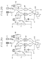
- Figs. 1 to 4 show embodiments of the present invention and Figs. 5 and 6 show conventional body fluid treating techniques.
- Figs. 5 and 6 show conventional body fluid treating techniques.
- the treatment block includes a couple of treating units or devices A1 and A2 each having the same treating capacity.
- Each of the treating units A1 and A2 connected in parallel is charged with an adsorbent capable of selectively adsorbing LDL and VLDL from the blood.
- a source B for supply of a regenerating liquid adapted to regenerate the treating ability of the units A1, A2 and a source C for supply of a washing liquid for forcing out the body fluid or regenerating liquid from each treating unit.
- each of the treating units A1 and A2 Connected to the upstream side of each of the treating units A1 and A2 are a body fluid feed line D, a regenerating liquid feed line F and a washing liquid feed line H.
- the regenerating liquid feed line F is joined with the washing liquid feed line H at a position before reaching the treating units.
- a body fluid return line E and a discharge line G(I) which serves as a regenerating liquid discharge line and a washing liquid discharge line.
- a plurality of lines or a line having branches can be used.
- Branching out of the discharge line G(I) is a confirmation line K, through which the effluent washing liquid discharged from the treating unit A1 or A2 is guided to a salt concentration measuring means J.
- a body fluid conveying pump L1 adapted to control the flow rate of body fluid
- a liquid supply pump L2 adapted to control the flow rate of the regenerating liquid or washing liquid.
- valves M1 to M12 are provided, thereby controlling the switching of flow passages for the body fluid, regenerating liquid or washing liquid.
- a plasma separator 1 to separate the plasma fraction from the blood to be treated
- a plasma pressure gage 2 to separate the plasma fraction from the blood to be treated
- a blood leak monitor 3 for alerting the operator to the entry of blood corpuscles into the plasma
- a supply side drip chamber 4 to prevent entry of air bubbles
- a feed plasma pressure gage 5 liquid discontinuation sensors 6 and 7, a feed liquid pressure gage 8, a drip chamber 9 in the regeneration system
- a filter 10 for preventing entry of the adsorbent into the plasma
- a return plasma pressure gage 11 to separate the plasma fraction from the blood to be treated
- a plasma pressure gage 2 to separate the plasma fraction from the blood to be treated
- a blood leak monitor 3 for alerting the operator to the entry of blood corpuscles into the plasma
- a supply side drip chamber 4 to prevent entry of air bubbles
- a feed plasma pressure gage 5 liquid discontinuation sensors 6 and 7, a feed liquid pressure gage 8
- a drip chamber 9 in the regeneration system
- the plasma separator 1 includes a separation membrane to separate and extract the plasma fraction from the blood.
- the blood corpuscles are liable to adhere to the separation membrane and, once deposited, cannot be readily detached.
- the corpuscles play particularly important roles, the loss thereof should be minimized in the treatment.
- the corpuscles remaining in the plasma separator has hitherto been recovered by passing physiological saline through the separator after completion of treatment.
- a thorough recovery of corpuscles demands the use of a large quantity of physiological saline, and when such a large quantity of saline is used, there occurs a sudden increase in the intracorporeal circulation to induce a decrease in colloid osmotic pressure, a change in blood pressure and other adverse effects due to blood dilution such as anemia.
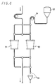
- Fig. 4 is a view to illustrate a method for recovery of blood cells from the plasma separator 1, where the treating units A1 and A2 are represented as a single block for convenience's sake. After the treatment, the plasma fraction remaining in the treating block 40 is guided to the plasma separator 1 so as to pass in the direction reverse to the plasma separation direction, whereby the blood cells adhering to the membrane are released and recovered.
- the plasma separator 1 is shut off at a suitable place S on the side where the collected blood enters into the separator, and at the same time, the body fluid pump L1 is driven in the reverse direction to send back the plasma fraction remaining in the treating unit A1 or A2 and other treating block circuit to the plasma separator 1 where it undergoes reverse osmosis to thereby recover the blood corpuscles from the membrane.
- the plasma fraction which has a high affinity for the corpuscles is utilized as a medium for recovery of corpuscles in the above method, the ability of releasing the corpuscles from the separation membrane is far higher than physiological saline and, therefore, the volume of plasma required for this purpose is small as compared with saline and there is no adverse effect on the human body.
- this medium for recovery of corpuscles is the plasma fraction of the patient's own blood, there is no risk of adverse influence on the blood components.
- the total capacity of the above-mentioned treating units A1 and A2 may be less than one-half of the capacity of a single treating unit conventionally used. The reason is that although the capacity of removing LDL and VLDL from the plasma depends on the total amount of adsorbent used, the regeneration and reuse of the treating units enables to reduce the amount of adsorbent required because of increase in the total amount of adsorbent utilized for the treatment.
- the regenerating liquid is selected according to the adsorbent used.
- adsorbent composed of a water-insoluble support and a polyanion compound, immobilized thereto, capable of adsorbing harmful substances in the blood such as LDL and VLDL
- electrolytes are, for instance, sodium chloride, potassium chloride, calcium chloride, sodium phosphate, potassium phosphate, sodium carbonate, potassium carbonate, and the like.
- adsorbent is a dextrane-immobilized cellulose gel
- an aqueous solution of sodium chloride having a concentration of 0.18 to 6 moles/liter, especially 0.3 to 1 mole/liter, is preferably used.
- Physiologically harmless liquids e.g. Ringer solution and physiological saline (salt concentration: about 0.15 mole/liter)
- the washing liquids are physiologically harmless, because they may come into contact with the body fluids or may flow into the human body.
- the salt concentration measuring means J is intended to confirm that the salt concentration of the effluent from the treating unit is equal to the physiological salt concentration, and may for example be a conductivity meter, although this is not an exclusive choice. Any devices or means which can attain this purpose can be used.
- the plasma separator 1 may be any of the known types, e.g. a membrane separator using a semi-permeable membrane for blood filtration or a centrifugal plasma separator which utilizes a difference in sedimentation constant.
- the valves M1 to M12 may each be a clamp, a pinch cock or the like.
- a solenoid pinch cock is preferred in that it is simple in construction and control. When the solenoid pinch cock is such that it is open when current flows and closed when current does not flows, accidents in emergencies such as an interruption of current can be prevented. Further, accident due to an erratic operation can be prevented when the action of the pinch cock is detected by an appropriate sensor.
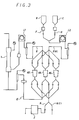
- a method for treating a body fluid using the above-mentioned treating circuit will be explained with reference to Fig. 2(A) to 2(J).
- the open condition of any of valves M1 to M12 is indicated by white dot ⁇ and the closed condition by black dot ⁇ .
- any circuit line in which a liquid such as a body fluid is flowing is indicated by a solid line, while any circuit line in which no liquid is flowing is indicated by a broken line.
- A1 is the pre-stage unit and A2 is the post-stage unit.
- treating devices or units can be reused and, moreover, line switching can be effected safely without entry of the regenerating liquid into the human body or without contact between the regenerating liquid and the body fluid.
- the alternating and repeated use of the treating units A1 and A2 not only enables to drastically decrease the amount of the adsorbent to be used, but also helps to reduce the volume of the treating device and minimize the extracorporeal circulation volume of the blood.
- the above embodiment employs two treating units but it is, of course, possible to provide three or more treating units within the treating block.
- an embodiment comprising three treating units, namely first unit A3, second unit A4 and third unit A5, is shown in Fig. 3.
- the treating units A3, A4 and A5 are used for the treatment in succession and repetition in the order of the first, second and third units, provided that the following steps (a) and (b) are added to the above-mentioned steps.
- the regeneration and washing of the first unit A3 are to be completed only by the time when the treatment of the body fluid by the third unit A5 is completed.
- the present invention offers the following advantages.
- the present invention provides a body fluid treating circuit which reduces the burden on the patients and is safe to the patients.
Claims (2)
- Regenerierbare Behandlungsvorrichtung für Körperflüssigkeit, die in einem extrakorporalen Kreislauf einen Sammelblock für Körperflüssigkeit zum Sammeln von Körperflüssigkeit aus einem menschlichen Körper, einen Behandlungsblock zum Unterwerfen der gesammelten Körperflüssigkeit unter eine vorbestimmte Behandlung, und einen Rückführblock für Körperflüssigkeit zum Rückführen der behandelten Körperflüssigkeit zu dem menschlichen Köper umfaßt, wobei der Behandlungsblock umfaßt:a) mehrere im Gleichstrom angeordnete Behandlungseinheiten (A);b) eine Quelle (B) zum Zuführen einer Regenerierungsflüssigkeit zum Regenerieren der Behandlungseinheit (A) zum Wiederherstellen ihrer Behandlungsfähigkeit;c) eine Quelle (C) zum Zuführen einer Spülflüssigkeit zum Verdrängen der in jeder der Behandlungseinheiten (A) befindlichen Körperflüssigkeit oder der Regenerierungsflüssigkeit aus dieser;d) Zuführleitungen (D) für Körperflüssigkeit zum Zuführen der gesammelten Körperflüssigkeit zu jeder der Behandlungseinheiten, wobei die Leitungen mit der Aufstromseite jeder der Behandlungseinheiten (A) verbunden sind;e) Rückführleitungen (E) für Körperflüssigkeit zum Transportieren der behandelten Körperflüssigkeit zu dem Rückführblock für Körperflüssigkeit, wobei die Leitungen mit der Abstromseite jeder der Behandlungseinheiten (A) verbunden sind;f) Zuführleitungen (F) für Regenerierungsflüssigkeit zum Zuführen der Regenerierungsflüssigkeit zu jeder der Behandlungseinheiten (A) aus der Zuführquelle (B) für Regenerierungsflüssigkeit, wobei die Leitungen mit der Aufstromseite jeder der Behandlungseinheiten (A) verbunden sind;g) Abführleitungen (G) für Regenerierungsflüssigkeit zum Abführen des Regenerierungsflüssigkeitsausflusses aus den Behandlungseinheiten zur Außenseite des Kreislaufs, wobei die Leitungen mit der Abstromseite jeder der Behandlungseinheiten (A) verbunden sind;h) Zuführleitungen (H) für Spülflüssigheit zum Zuführen der Spülflüssigkeit zu jeder der Behandlungseinheiten (A) aus der Zuführquelle (C), wobei die Leitungen mit der Aufstromseite jeder der Behandlungseiheiten (A) verbunden sind;(i) Abführleitungen (G) für Spülflüssigkeit zum Abführen des Spülflüssigkeitsausflusses aus den Behandlungseinheiten zur Außenseite des Kreislaufs, wobei die Leitungen mit der Abstromseite jeder der Behandlungseinheiten (A) verbunden sind;j) eine Durchflußsteuereinrichtung (L) zum Steuern der Durchflußraten der Körperflüssigkeit, Regenerierungsflüssigkeit bzw. Spülflüssigkeit in dem Kreislauf;k) Schalteinrichtungen (M) zum selektiven Schalten der Verbindungen der entsprechenden Leitungen von mindestens einer Behandlungseinheit (A1) zu der anderen Einheit A2; undl) Sensoreinrichtungen zum Abtasten von Eigenschaften der ausströmenden Spülflüssigkeit an der Abstromseite der Behandlungseinheiten (A);dadurch gekennzeichnet, daß
die Zuführleitungen (F; H) für die Regenerierungsflüssigkeit und die Spülflüssigkeit mit den Behandlungseinheiten durch eine gemeinsame Durchflußsteuereinrichtung (L2) und Steuereinrichtungen (M4; M6), die von den Steuereinrichtungen (M3; M5) der Zuführleitung D für Körperflüssigkeit getrennt sind, verbunden sind, daß jede Abführleitung (G) für Regenerierungsflüssigkeit Steuereinrichtungen (M8; M10) umfaßt, die von Steuereinrichtungen (M7; M9) der Rückführleitung (E) für Körperflüssigkeit getrennt sind, und daß die Sensoreinrichtung eine Meßeinrichtung (J) für die Salzkonzentration zum Bestimmen der Salzkonzentration der aus jeder der Behandlungseinheiten (A) ausströmenden Spülflüssigkeit ist, wobei eine Bestätigungsleitung (K), die den Spülflüssigkeitsausfluß zu der Meßeinrichtung (J) für die Salzkonzentration leitet, entweder mit der Abstromseite jeder der Behandlungseinheiten JA) verbunden ist oder von den Abführleitungen (G) für Spülflüssigkeit abzweigt. - Vorrichtung nach Anspruch 1, dadurch gekennzeichnet, daß eine Schließeinrichtung (S) stromaufwärts zu einem Plasmaseparator (1) so angeordnet ist, daß die in dem Behandlungsblock zurückbleibende Plasmafraktion in den Plasmaseparator (1) durch die Zuführleitungen (D) für Körperflüssigkeit in Gegenrichtung zu der Trennung des Plasmas durch entgegengesetztes Antreiben der Durchflußsteuereinrichtung (L) zum Steuern der Durchflußrate der in den Zuführleitungen (D) für Körperflüssigkeit befindlichen Körperflüssigkeit geführt werden kann, und zurück zu dem Rückführblock für Körperflüssigkeit durch den Plasmaseparator (1) und danach stromabwärts des Plasmaseparators (1) geführt wird.
Applications Claiming Priority (4)
| Application Number | Priority Date | Filing Date | Title |
|---|---|---|---|
| JP61234200A JPS6389168A (ja) | 1986-09-30 | 1986-09-30 | 再生式体液処理装置による処理体液の製造方法 |
| JP234200/86 | 1986-09-30 | ||
| JP236783/86 | 1986-10-03 | ||
| JP61236783A JPS6392353A (ja) | 1986-10-03 | 1986-10-03 | 血液処理回路内の血液回収方法 |
Publications (3)
| Publication Number | Publication Date |
|---|---|
| EP0263384A2 EP0263384A2 (de) | 1988-04-13 |
| EP0263384A3 EP0263384A3 (en) | 1989-07-26 |
| EP0263384B1 true EP0263384B1 (de) | 1993-06-09 |
Family
ID=26531423
Family Applications (1)
| Application Number | Title | Priority Date | Filing Date |
|---|---|---|---|
| EP87114077A Expired - Lifetime EP0263384B1 (de) | 1986-09-30 | 1987-09-26 | Behandlungskreislauf zum Regenerieren von Körperflüssigkeit |
Country Status (3)
| Country | Link |
|---|---|
| US (2) | US4863590A (de) |
| EP (1) | EP0263384B1 (de) |
| DE (1) | DE3786138T2 (de) |
Families Citing this family (15)
| Publication number | Priority date | Publication date | Assignee | Title |
|---|---|---|---|---|
| EP0478692B1 (de) * | 1989-06-20 | 1996-01-24 | The Board Of Regents Of The University Of Washington | Hemodialysesystem |
| SE501068C2 (sv) * | 1989-10-04 | 1994-11-07 | Caustec Ab | Förfarande och anordning för filtrering av en suspension |
| US5141501A (en) * | 1990-05-21 | 1992-08-25 | Vernay Laboratories, Inc. | Suction metering and mixing device |
| US5163926A (en) * | 1990-05-21 | 1992-11-17 | Vernay Laboratories, Inc. | Suction metering and mixing device |
| US5690835A (en) | 1991-12-23 | 1997-11-25 | Baxter International Inc. | Systems and methods for on line collection of cellular blood components that assure donor comfort |
| US5549834A (en) | 1991-12-23 | 1996-08-27 | Baxter International Inc. | Systems and methods for reducing the number of leukocytes in cellular products like platelets harvested for therapeutic purposes |
| US5622626A (en) * | 1994-04-15 | 1997-04-22 | Pall Corporation | Multiple compartment filter and method for processing parenteral fluid |
| DE4416616C2 (de) * | 1994-05-11 | 1997-05-22 | Fichtel & Sachs Ag | Gehäuse |
| WO1997016527A1 (en) * | 1995-10-30 | 1997-05-09 | Cellex Biosciences, Inc. | Cultureware for bioartificial liver |
| US5989438A (en) * | 1997-12-12 | 1999-11-23 | Baxter International Inc. | Active blood filter and method for active blood filtration |
| JP4638986B2 (ja) | 1998-10-16 | 2011-02-23 | テルモ メディカル コーポレイション | 血液処理装置 |
| CA2369576C (en) | 1999-04-23 | 2005-07-05 | William Frederick Weitzel | Extracorporeal circuit and related methods |
| JP5619270B2 (ja) * | 2011-02-23 | 2014-11-05 | 旭化成メディカル株式会社 | 血液浄化装置 |
| DE102015002073A1 (de) | 2015-02-18 | 2016-08-18 | Fresenius Medical Care Deutschland Gmbh | Vorrichtung zur Durchführung einer Apheresebehandlung |
| JP6765232B2 (ja) | 2016-06-30 | 2020-10-07 | シスメックス株式会社 | 免疫複合体転移法により被検物質を検出するための抗体試薬及びその製造方法、並びにその抗体試薬の利用 |
Family Cites Families (6)
| Publication number | Priority date | Publication date | Assignee | Title |
|---|---|---|---|---|
| US4118314A (en) * | 1974-01-09 | 1978-10-03 | Seisan Kaihatsu Kagaku Kenkyusho | Apparatus for treatment of artificial kidney dialyzing fluid |
| BR8205658A (pt) * | 1981-10-02 | 1983-08-30 | Du Pont | Processo e aparelho de plasmaferese por filtracao |
| SE451946B (sv) * | 1982-12-10 | 1987-11-09 | Gambro Lundia Ab | Anordning for avlegsnande av en eller flera fraktioner ur helblod, plasma eller liknande kroppsvetskor |
| JPS61119271A (ja) * | 1984-11-13 | 1986-06-06 | 鐘淵化学工業株式会社 | 血液成分処理回路及び血液成分処理方法 |
| JPH0622626B2 (ja) * | 1985-01-11 | 1994-03-30 | 鐘淵化学工業株式会社 | 体外循環治療用吸着体の再生方法 |
| JPS61164562A (ja) * | 1985-01-16 | 1986-07-25 | 鐘淵化学工業株式会社 | 体液成分処理装置及び体液成分処理方法 |
-
1987
- 1987-09-26 EP EP87114077A patent/EP0263384B1/de not_active Expired - Lifetime
- 1987-09-26 DE DE87114077T patent/DE3786138T2/de not_active Expired - Fee Related
- 1987-09-29 US US07/102,691 patent/US4863590A/en not_active Expired - Lifetime
-
1988
- 1988-05-06 US US07/190,985 patent/US4855057A/en not_active Expired - Lifetime
Also Published As
| Publication number | Publication date |
|---|---|
| EP0263384A2 (de) | 1988-04-13 |
| US4863590A (en) | 1989-09-05 |
| US4855057A (en) | 1989-08-08 |
| EP0263384A3 (en) | 1989-07-26 |
| DE3786138T2 (de) | 1993-10-07 |
| DE3786138D1 (de) | 1993-07-15 |
Similar Documents
| Publication | Publication Date | Title |
|---|---|---|
| EP0263384B1 (de) | Behandlungskreislauf zum Regenerieren von Körperflüssigkeit | |
| US11446417B2 (en) | Filtration system for preparation of fluids for medical applications | |
| US7169303B2 (en) | Sorbent reactor for extracorporeal blood treatment systems, peritoneal dialysis systems, and other body fluid treatment systems | |
| EP0951303B1 (de) | Vorrichtung zur herstellung von einer ersatzlösung | |
| US6582385B2 (en) | Hemofiltration system including ultrafiltrate purification and re-infusion system | |
| US5252213A (en) | Dry dialysate composition | |
| EP1592494B1 (de) | Chargenfiltriersystem zur herstellung einer sterilen ersatzflüssigkeit für nierenbehandlungen | |
| EP0087171A1 (de) | Sicherheitsüberprüfungsanordnung für ein Filter | |
| JP4384437B2 (ja) | 体外血液処理を中断するかまたは修正された流速で体外血液処理を継続する方法および体外血液処理装置 | |
| US20080243045A1 (en) | Apparatus and method for the treatment of blood | |
| KR20040093102A (ko) | 단백질이 부분적으로 결합된 물질을 제거하는 방법 및 장치 | |
| EP2280748A1 (de) | Hämodialyse- oder hämo(dia)filtrationsgerät und verfahren zur steuerung eines hämodialyse- oder hämo(dia)filtrationsgeräts | |
| KR20150097785A (ko) | 혈액투석여과법 | |
| WO2006054367A1 (ja) | 自動返血装置 | |
| JP2003320023A6 (ja) | 体外血液処理を中断するかまたは修正された流速で体外血液処理を継続する方法および体外血液処理装置 | |
| CN100493633C (zh) | 人工肝肾支持系统 | |
| US4300551A (en) | Method for treating schizophrenia | |
| EP3731893B1 (de) | Vorrichtung zur extrakorporalen blutbehandlung | |
| CN113350593B (zh) | 血液净化设备的控制方法、血液净化设备及存储介质 | |
| CN209900240U (zh) | 佩戴式滤过型人工肾装置 | |
| US20040143207A1 (en) | Apparatus usable in haemofiltration treatment | |
| US20050077228A1 (en) | Blood treatment machine and unit | |
| CA1271383A (en) | Regeneration type body fluid treating circuit and method for treating body fluid | |
| WO2017171064A1 (ja) | 血液浄化システム、及びそのプライミング方法 | |
| JPH06114102A (ja) | 血液透析濾過装置 |
Legal Events
| Date | Code | Title | Description |
|---|---|---|---|
| PUAI | Public reference made under article 153(3) epc to a published international application that has entered the european phase |
Free format text: ORIGINAL CODE: 0009012 |
|
| AK | Designated contracting states |
Kind code of ref document: A2 Designated state(s): BE CH DE FR GB IT LI NL SE |
|
| PUAL | Search report despatched |
Free format text: ORIGINAL CODE: 0009013 |
|
| AK | Designated contracting states |
Kind code of ref document: A3 Designated state(s): BE CH DE FR GB IT LI NL SE |
|
| 17P | Request for examination filed |
Effective date: 19890902 |
|
| 17Q | First examination report despatched |
Effective date: 19901219 |
|
| GRAA | (expected) grant |
Free format text: ORIGINAL CODE: 0009210 |
|
| AK | Designated contracting states |
Kind code of ref document: B1 Designated state(s): BE CH DE FR GB IT LI NL SE |
|
| REF | Corresponds to: |
Ref document number: 3786138 Country of ref document: DE Date of ref document: 19930715 |
|
| ET | Fr: translation filed | ||
| ITF | It: translation for a ep patent filed |
Owner name: STUDIO CONS. BREVETTUAL |
|
| PLBE | No opposition filed within time limit |
Free format text: ORIGINAL CODE: 0009261 |
|
| STAA | Information on the status of an ep patent application or granted ep patent |
Free format text: STATUS: NO OPPOSITION FILED WITHIN TIME LIMIT |
|
| 26N | No opposition filed | ||
| EAL | Se: european patent in force in sweden |
Ref document number: 87114077.8 |
|
| REG | Reference to a national code |
Ref country code: GB Ref legal event code: IF02 |
|
| PGFP | Annual fee paid to national office [announced via postgrant information from national office to epo] |
Ref country code: NL Payment date: 20040905 Year of fee payment: 18 |
|
| PGFP | Annual fee paid to national office [announced via postgrant information from national office to epo] |
Ref country code: SE Payment date: 20040906 Year of fee payment: 18 |
|
| PGFP | Annual fee paid to national office [announced via postgrant information from national office to epo] |
Ref country code: FR Payment date: 20040908 Year of fee payment: 18 |
|
| PGFP | Annual fee paid to national office [announced via postgrant information from national office to epo] |
Ref country code: GB Payment date: 20040922 Year of fee payment: 18 |
|
| PGFP | Annual fee paid to national office [announced via postgrant information from national office to epo] |
Ref country code: DE Payment date: 20040923 Year of fee payment: 18 |
|
| PGFP | Annual fee paid to national office [announced via postgrant information from national office to epo] |
Ref country code: CH Payment date: 20040929 Year of fee payment: 18 |
|
| PGFP | Annual fee paid to national office [announced via postgrant information from national office to epo] |
Ref country code: BE Payment date: 20041122 Year of fee payment: 18 |
|
| PG25 | Lapsed in a contracting state [announced via postgrant information from national office to epo] |
Ref country code: IT Free format text: LAPSE BECAUSE OF NON-PAYMENT OF DUE FEES Effective date: 20050926 Ref country code: GB Free format text: LAPSE BECAUSE OF NON-PAYMENT OF DUE FEES Effective date: 20050926 |
|
| PG25 | Lapsed in a contracting state [announced via postgrant information from national office to epo] |
Ref country code: SE Free format text: LAPSE BECAUSE OF NON-PAYMENT OF DUE FEES Effective date: 20050927 |
|
| PG25 | Lapsed in a contracting state [announced via postgrant information from national office to epo] |
Ref country code: LI Free format text: LAPSE BECAUSE OF NON-PAYMENT OF DUE FEES Effective date: 20050930 Ref country code: CH Free format text: LAPSE BECAUSE OF NON-PAYMENT OF DUE FEES Effective date: 20050930 Ref country code: BE Free format text: LAPSE BECAUSE OF NON-PAYMENT OF DUE FEES Effective date: 20050930 |
|
| PG25 | Lapsed in a contracting state [announced via postgrant information from national office to epo] |
Ref country code: NL Free format text: LAPSE BECAUSE OF NON-PAYMENT OF DUE FEES Effective date: 20060401 Ref country code: DE Free format text: LAPSE BECAUSE OF NON-PAYMENT OF DUE FEES Effective date: 20060401 |
|
| REG | Reference to a national code |
Ref country code: CH Ref legal event code: PL |
|
| EUG | Se: european patent has lapsed | ||
| GBPC | Gb: european patent ceased through non-payment of renewal fee |
Effective date: 20050926 |
|
| PG25 | Lapsed in a contracting state [announced via postgrant information from national office to epo] |
Ref country code: FR Free format text: LAPSE BECAUSE OF NON-PAYMENT OF DUE FEES Effective date: 20060531 |
|
| NLV4 | Nl: lapsed or anulled due to non-payment of the annual fee |
Effective date: 20060401 |
|
| REG | Reference to a national code |
Ref country code: FR Ref legal event code: ST Effective date: 20060531 |
|
| BERE | Be: lapsed |
Owner name: *KANEGAFUCHI KAGAKU KOGYO K.K. Effective date: 20050930 Owner name: *YOKOGAWA ELECTRIC CORP. Effective date: 20050930 |