EP0262918A2 - Koaxialkabelverbinder mit einstellbarer Phase - Google Patents
Koaxialkabelverbinder mit einstellbarer Phase Download PDFInfo
- Publication number
- EP0262918A2 EP0262918A2 EP87308607A EP87308607A EP0262918A2 EP 0262918 A2 EP0262918 A2 EP 0262918A2 EP 87308607 A EP87308607 A EP 87308607A EP 87308607 A EP87308607 A EP 87308607A EP 0262918 A2 EP0262918 A2 EP 0262918A2
- Authority
- EP
- European Patent Office
- Prior art keywords
- coaxial cable
- connector body
- connector
- coupling
- central
- Prior art date
- Legal status (The legal status is an assumption and is not a legal conclusion. Google has not performed a legal analysis and makes no representation as to the accuracy of the status listed.)
- Granted
Links
Images
Classifications
-
- H—ELECTRICITY
- H01—ELECTRIC ELEMENTS
- H01R—ELECTRICALLY-CONDUCTIVE CONNECTIONS; STRUCTURAL ASSOCIATIONS OF A PLURALITY OF MUTUALLY-INSULATED ELECTRICAL CONNECTING ELEMENTS; COUPLING DEVICES; CURRENT COLLECTORS
- H01R24/00—Two-part coupling devices, or either of their cooperating parts, characterised by their overall structure
- H01R24/38—Two-part coupling devices, or either of their cooperating parts, characterised by their overall structure having concentrically or coaxially arranged contacts
- H01R24/40—Two-part coupling devices, or either of their cooperating parts, characterised by their overall structure having concentrically or coaxially arranged contacts specially adapted for high frequency
- H01R24/42—Two-part coupling devices, or either of their cooperating parts, characterised by their overall structure having concentrically or coaxially arranged contacts specially adapted for high frequency comprising impedance matching means or electrical components, e.g. filters or switches
- H01R24/44—Two-part coupling devices, or either of their cooperating parts, characterised by their overall structure having concentrically or coaxially arranged contacts specially adapted for high frequency comprising impedance matching means or electrical components, e.g. filters or switches comprising impedance matching means
-
- H—ELECTRICITY
- H01—ELECTRIC ELEMENTS
- H01R—ELECTRICALLY-CONDUCTIVE CONNECTIONS; STRUCTURAL ASSOCIATIONS OF A PLURALITY OF MUTUALLY-INSULATED ELECTRICAL CONNECTING ELEMENTS; COUPLING DEVICES; CURRENT COLLECTORS
- H01R2103/00—Two poles
Definitions
- the present invention relates to a coaxial cable connector which facilitates phase adjustment at terminal assembly of a coaxial cable.
- Coaxial connectors which are intended for interconnection of the ends of coaxial cables are known in the art and described, for example, in Japanese Patent Publication (Kokai) No. 57-44,980.
- coaxial connectors are used in a coaxial cable assembly incorporated into a phase-array system of a radar which requires a predetermined phase
- the coaxial connector is usually attached to one end of the coaxial cable, which preliminarily is provided with an excess length, which is then cut to a predetermined length on the basis of measurement of the phase by means of a pulse-reflection method.
- another coaxial connector is attached to the opposite end of the cable.
- the present invention seeks to eliminate the disadvantages inherent in the prior art devices and by providing a coaxial cable connector which permits adjustment of the phase of the cable without wastage of cable, and after connection is made.
- a coaxial cable connector comprising a cylindrical connector body of conductive metal supporting a metal coupling at one end of said connector body, the coupling being rotationally but not axially moveable with respect to said connector body, said connector body being threadingly engaged at its other end with a coaxial cable support member, said support member supporting a coaxial cable therein, which cable has a centre conductor and a conducting shield separated by a dielectric material, said centre conductor extending beyond said coaxial cable and into said connector body and having a bendable portion disposed within said connector body, said portion being affixed to a central connecting and conducting pin element therein extending into said coupling, said pin element being supported within said coupling by a dielectric material which separates said coupling and said element, said element being rotationally moveable within said dielectric, whereby, rotational movement of said coaxial cable support member relative to said connector body results in axial displacement of said support member with respect to said connector body thereby causing more or less slack in said bendable portion and
- the present invention also provides a coaxial cable connector comprising a cylindrical connector body of conductive metal supporting a metal coupling at one end of said connector body, the coupling being rotationally but not axially moveable with respect to said connector body, a coaxial cable support member supporting a coaxial cable being engaged at the other end of said connector body, said support and connector body being rotatably moveable with respect to each other, said coaxial cable having a centre conductor and shield separated by a dielectric material, said centre conductor extending into said connector body and being affixed to a contact element therein, said contact element being threadingly engaged with a central connecting and conducting pin element extending into said coupling and being supported within said coupling by a dielectric material which separates said coupling and said central connecting element, whereby rotational movement of said coaxial cable relative to the connector body results in axial displacement of said contact member with respect to said central connecting and conducting pin element therby providing means for adjusting the electrical path length of said connector to permit phase adjustment.
- the present invention further provides a coaxial cable connector comprising a cylindrical connector body, a central conducting element disposed in one end of the body and surrounded and supported by a dielectric, a coaxial cable support member fitted to the opposite end of said body and containing a coaxial cable having a centre conductor, said centre conductor having a portion extending beyond the end of the coaxial cable, said portion being electrically connected to said central conducting element and means for effecting relative axial movement between the coaxial cable and the central conducting element to vary the axial length of the conductive path between said central conducting element and said coaxial cable to cause phase adjustment therebetween.
- the connector may have at least one impedance-adjusting screw threaded into the connector body.
- a phase-adjustable coaxial cable connector in which phase adjustment is obtained by means which increase or decrease the axial length of the conductive path between a pin element at one end of the connector and the coaxial cable which extends into the connector.
- a phase-adjustable coaxial connector has a cylindrical connector body in which a central connecting pin element is supported by one end of the connector body through an insulation.
- An adjustable element which is supported by the other end of the connector body and contains a coaxial cable, can be moved axially with respect to the connector body while maintaining electrical contact therewith, and while maintaining electrical contact between the pin element and the centre conductor.
- an exposed length of the centre conductor between the pin element and the coaxial cable can kink to permit phase adjustment.
- the centre conductor is connected by a screw coupling to the pin element so that relative rotation between the centre conductor and the pin element shortens or lengthens the screw coupling.
- Connectors of the above-mentioned types are advantageous in that by attaching the central conductor of the coaxial cable to the central connecting element of the connector and by effecting relative axial movement, it is possible to adjust the phase of the coaxial cable and at the same time to protect the central conductor from concentration of stress.
- the connector body may have impedance-adjusting screws moveable with respect to the central conductor. These screws can be used for compensation of deviations in the value of the characteristic impedance.
- the adjustment element which supports one end of the coaxial cable is moveable axially with respect to the connector cylinder, it becomes possible to provide microscopic adjustment of the length (i.e. the electric length, and hence the phase-path length) of the cable assembly.
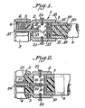
- the coaxial connector 1 has a connector cylinder body 2, which is made from a conductive material, in particular metal.
- Cylinder 2 supprts at its one end a coupling 4 which can rotate around the cylinder, but is restrained against axial movement by a cotter ring 3.
- the external part of coupling 4 is preferably formed as a hexagonal nut which can be rotated by a tool.
- a female thread 6, which is formed inside coupling 4 the latter can be attached to an appropriate male connecting counterpart, for example on an instrument.
- Coupling 4 is made of a conductive material such as metal, so that it is electrically connected to an external conductor 10 of a coaxial cable 9 through connector cylinder 2 and an adjustment element 8.
- Central conductor 11 of coaxial cable 9 is electrically connected with a central connecting element 13 which is supported in connector cylinder 2 by a dielectric body 12.
- central conductor 11 is preliminarly slackened or bent at a portion 14 and is then fixed in connecting element 13 by soldering.
- connecting element 13 has a solder feeding opening 15.
- External conductor 10 of coaxial cable 9 is connected to adjustment element 8 electrically and mechanically by soldering.
- adjustment element 8 has in its wall a through opening 16 for the supply of the solder.
- Adjustment element 8 has on its periphery a male thread 18 which is screwed into a female thread 17, formed inside connector cylinder 2 on the side opposite to coupling 4.
- the above-mentioned threaded connection makes it possible to adjust the length (i.e. the electrical length) of the entire cable assembly.
- the front end of coaxial cable 9 with the outer sheath 20 is supported by the connector through a recess 19 cut in the adjustment element on the end opposite to thread 18.
- the front end of the coaxial cable coated with sheath 20 is inserted into recess 19.
- other types of connections can be used for this purpose.
- the end of the cable can be threaded or pressed into a cable-supporting ring (not shown).
- phase-adjustable coaxial cable connector 1 of the above-described type after assembling the connector with coaxial cable 9, the microscopic adjustment of the phase variation of the phase of the cable, i.e. of its electric length, is performed by rotating adjustment body 8 with respect to cylinder body 2.
- the adjustment makes it possible to match the arbitrary characteristic impedance, which is determined by the amount of extension of kinked portion 14 of central conductor 11, with the characteristic impedance of coaxial cable 9. Variations can be compensated by impedance-adjusting screws 21 which are threaded into connector cylinder 2 towards the central conductor.
- a central coupling of adjustable axial length is provided.
- Central conductor 11 is attached mechanically and electrically to a contact element 22 by soldering.
- the soldering is performed by supplying solder through opening 23.
- Contact element 23 is provided on its outer periphery with a male thread 24, and is supported in the connector cylinder 2 through a dielectric body 25, which supports a central connector 26, having a female thread 27 engaged with the thread 24.
- the adjustment element 8 is rotated and therefore moved axially, i.e. when coaxial cable 9 is rotated, this movement causes rotation of contact element 22 as well.
- contact element 24 is screwed into ro out of central connector 26 thereby forming the adjustable coupling.
- the electric length of the coaxial cable, i.e. of central conductor 11 is changed.
- contact element 22 and central connecting element 26 are interconnected through a thread, but instead of this, they may have a sliding electric contact.
Landscapes
- Coupling Device And Connection With Printed Circuit (AREA)
- Details Of Connecting Devices For Male And Female Coupling (AREA)
- Cable Accessories (AREA)
- Multi-Conductor Connections (AREA)
Priority Applications (1)
| Application Number | Priority Date | Filing Date | Title |
|---|---|---|---|
| AT87308607T ATE74692T1 (de) | 1986-10-03 | 1987-09-29 | Koaxialkabelverbinder mit einstellbarer phase. |
Applications Claiming Priority (2)
| Application Number | Priority Date | Filing Date | Title |
|---|---|---|---|
| JP61235838A JPS6391981A (ja) | 1986-10-03 | 1986-10-03 | 位相調整同軸コネクタ |
| JP235838/86 | 1986-10-03 |
Publications (3)
| Publication Number | Publication Date |
|---|---|
| EP0262918A2 true EP0262918A2 (de) | 1988-04-06 |
| EP0262918A3 EP0262918A3 (en) | 1988-08-10 |
| EP0262918B1 EP0262918B1 (de) | 1992-04-08 |
Family
ID=16992011
Family Applications (1)
| Application Number | Title | Priority Date | Filing Date |
|---|---|---|---|
| EP87308607A Expired - Lifetime EP0262918B1 (de) | 1986-10-03 | 1987-09-29 | Koaxialkabelverbinder mit einstellbarer Phase |
Country Status (9)
| Country | Link |
|---|---|
| US (1) | US4772223A (de) |
| EP (1) | EP0262918B1 (de) |
| JP (1) | JPS6391981A (de) |
| AT (1) | ATE74692T1 (de) |
| AU (1) | AU591426B2 (de) |
| DE (1) | DE3778107D1 (de) |
| GB (1) | GB2196802B (de) |
| HK (2) | HK102491A (de) |
| SG (1) | SG93591G (de) |
Cited By (1)
| Publication number | Priority date | Publication date | Assignee | Title |
|---|---|---|---|---|
| WO1993011580A1 (en) * | 1991-11-26 | 1993-06-10 | Allied-Signal Inc. | An apparatus and method for correcting electrical path length phase errors |
Families Citing this family (20)
| Publication number | Priority date | Publication date | Assignee | Title |
|---|---|---|---|---|
| JPS6391982A (ja) * | 1986-10-03 | 1988-04-22 | 株式会社 潤工社 | 位相調整同軸コネクタ |
| JPS6391981A (ja) * | 1986-10-03 | 1988-04-22 | 株式会社 潤工社 | 位相調整同軸コネクタ |
| JPS6387790U (de) * | 1986-11-27 | 1988-06-08 | ||
| US4954669A (en) * | 1989-01-25 | 1990-09-04 | W. L. Gore & Associates, Inc. | Coaxial cable connector assembly |
| JPH0810933Y2 (ja) * | 1990-01-16 | 1996-03-29 | 日本電気株式会社 | 同軸型コネクタ |
| JP2868973B2 (ja) * | 1993-06-08 | 1999-03-10 | 矢崎総業株式会社 | シールドコネクタ |
| GB2306059A (en) * | 1995-06-01 | 1997-04-23 | Huber+Suhner Ag | Axially adjustable coaxial electrical connecting line with constant impedance |
| FI101329B (fi) * | 1996-08-29 | 1998-05-29 | Nokia Telecommunications Oy | Menetelmä tukiaseman summausverkon virittämiseksi |
| US6176716B1 (en) * | 1997-07-11 | 2001-01-23 | Monster Cable Products, Inc. | Interchangeable electrical connector |
| JP3383222B2 (ja) * | 1998-08-28 | 2003-03-04 | ケル株式会社 | ケーブル接続用コネクタ |
| EP1182744B1 (de) * | 2000-08-19 | 2004-07-14 | Spinner GmbH Elektrotechnische Fabrik | Phasenabgleichverfahren für Koaxialkabel und zugehöriger Steckverbinder |
| US6667440B2 (en) * | 2002-03-06 | 2003-12-23 | Commscope Properties, Llc | Coaxial cable jumper assembly including plated outer conductor and associated methods |
| US7128603B2 (en) * | 2002-05-08 | 2006-10-31 | Corning Gilbert Inc. | Sealed coaxial cable connector and related method |
| US6790081B2 (en) * | 2002-05-08 | 2004-09-14 | Corning Gilbert Inc. | Sealed coaxial cable connector and related method |
| US7883363B2 (en) * | 2009-06-05 | 2011-02-08 | John Mezzalingua Associates, Inc. | Phase adjustable adapter |
| US20110201232A1 (en) * | 2010-02-16 | 2011-08-18 | Andrew Llc | Connector for coaxial cable having rotational joint between insulator member and center contact and associated methods |
| TWM470363U (zh) * | 2013-07-03 | 2014-01-11 | Infinet Technology Ltd | 電纜組件及其訊號傳輸系統 |
| JP6772041B2 (ja) * | 2016-11-25 | 2020-10-21 | ホシデン株式会社 | コネクタ端子 |
| KR102123717B1 (ko) * | 2016-12-30 | 2020-06-16 | 주식회사 에이플러스알에프 | 동축케이블 연결용 커넥터 |
| KR102123716B1 (ko) * | 2016-12-30 | 2020-06-16 | 주식회사 에이플러스알에프 | 알에프 신호조절 기능을 갖는 커넥터 |
Family Cites Families (12)
| Publication number | Priority date | Publication date | Assignee | Title |
|---|---|---|---|---|
| DE915100C (de) * | 1945-04-07 | 1954-07-15 | Siemens Ag | Verfahren zum Ausgleich der elektrischen Laenge von Hochfrequenzkabeln und -leitungen |
| US2644140A (en) * | 1945-10-19 | 1953-06-30 | Us Sec War | Variable-length transmission line |
| GB1006665A (en) * | 1962-04-19 | 1965-10-06 | James Stanley Fort | Improvements in or relating to electrical coaxial cable end connector |
| US3480888A (en) * | 1966-03-03 | 1969-11-25 | Collins Radio Co | Electronically tuned filter |
| JPS51145042A (en) * | 1975-06-06 | 1976-12-13 | Mitsubishi Electric Corp | Boiling type refrigeration system |
| DE2914902C2 (de) * | 1979-04-12 | 1983-04-07 | Philips Kommunikations Industrie AG, 8500 Nürnberg | Koaxialleitungsstecker für Meßzwecke |
| FR2545659B1 (fr) * | 1983-05-04 | 1985-07-05 | Cables De Lyon Geoffroy Delore | Prolongateur d'ame d'un cable coaxial, et connecteur muni d'un tel prolongateur |
| US4648683A (en) * | 1985-05-28 | 1987-03-10 | Hewlett-Packard Company | Adjustable length slotless female contact for connectors |
| US4779067A (en) * | 1985-11-14 | 1988-10-18 | Johanson Manufacturing Corporation | Microwave phase trimmer |
| US4687279A (en) * | 1985-12-20 | 1987-08-18 | Storm Products Co. | High frequency coaxial connector adaptor |
| JPS6391982A (ja) * | 1986-10-03 | 1988-04-22 | 株式会社 潤工社 | 位相調整同軸コネクタ |
| JPS6391981A (ja) * | 1986-10-03 | 1988-04-22 | 株式会社 潤工社 | 位相調整同軸コネクタ |
-
1986
- 1986-10-03 JP JP61235838A patent/JPS6391981A/ja active Pending
-
1987
- 1987-09-22 AU AU78857/87A patent/AU591426B2/en not_active Ceased
- 1987-09-29 GB GB8722857A patent/GB2196802B/en not_active Expired - Fee Related
- 1987-09-29 AT AT87308607T patent/ATE74692T1/de active
- 1987-09-29 DE DE8787308607T patent/DE3778107D1/de not_active Expired - Fee Related
- 1987-09-29 EP EP87308607A patent/EP0262918B1/de not_active Expired - Lifetime
- 1987-10-02 US US07/104,417 patent/US4772223A/en not_active Expired - Fee Related
-
1991
- 1991-11-07 SG SG935/91A patent/SG93591G/en unknown
- 1991-12-12 HK HK1024/91A patent/HK102491A/xx unknown
-
1993
- 1993-12-30 HK HK1436/93A patent/HK143693A/en not_active IP Right Cessation
Cited By (1)
| Publication number | Priority date | Publication date | Assignee | Title |
|---|---|---|---|---|
| WO1993011580A1 (en) * | 1991-11-26 | 1993-06-10 | Allied-Signal Inc. | An apparatus and method for correcting electrical path length phase errors |
Also Published As
| Publication number | Publication date |
|---|---|
| ATE74692T1 (de) | 1992-04-15 |
| GB8722857D0 (en) | 1987-11-04 |
| DE3778107D1 (de) | 1992-05-14 |
| HK102491A (en) | 1991-12-20 |
| GB2196802B (en) | 1990-06-20 |
| HK143693A (en) | 1994-01-07 |
| SG93591G (en) | 1991-12-13 |
| EP0262918B1 (de) | 1992-04-08 |
| JPS6391981A (ja) | 1988-04-22 |
| EP0262918A3 (en) | 1988-08-10 |
| AU7885787A (en) | 1988-04-14 |
| AU591426B2 (en) | 1989-11-30 |
| US4772223A (en) | 1988-09-20 |
| GB2196802A (en) | 1988-05-05 |
Similar Documents
| Publication | Publication Date | Title |
|---|---|---|
| EP0262918B1 (de) | Koaxialkabelverbinder mit einstellbarer Phase | |
| EP0484434B1 (de) | Kabelkragenabschluss | |
| CA1242008A (en) | Coaxial cable connector | |
| US5490801A (en) | Electrical terminal to be crimped to a coaxial cable conductor, and crimped coaxial connection thereof | |
| CA1077591A (en) | Electrical connectors for coaxial cables | |
| US4397516A (en) | Cable termination apparatus | |
| US5790361A (en) | Coaxial surge protector with impedance matching | |
| US6802738B1 (en) | Connector for coaxial cable with multiple start threads | |
| EP0161910A2 (de) | Verbinder für mehradriges Kabel | |
| EP0920088A3 (de) | Rechtwinkliger Koaxialkabelverbinder | |
| US20020182940A1 (en) | Cable and phone plug assembly and method for producing it | |
| JPH0613127A (ja) | ケーブルプラグコネクタ及びケーブル案内機構 | |
| FR2432223A1 (fr) | Procede et dispositif pour la liaison d'un cable co-axial a un accessoire de circuit electrique | |
| EP1665473A1 (de) | Coaxialwinkel-verbinder | |
| US4741702A (en) | Phase-adjustable coaxial cable connector | |
| US3757278A (en) | Subminiature coaxial contact | |
| EP0111162A1 (de) | Gekapselter, abgeschirmter und geerdeter Steckverbinder | |
| US5562482A (en) | Coaxial cable connector and method of assembling | |
| EP1191655B1 (de) | Krimpfreier Zugentlastungsabschluss für Koaxialkabel | |
| CA2084410A1 (en) | Electrical connector | |
| CA1115370A (en) | Connector plug for coaxial cables | |
| US11695246B2 (en) | Controlled-impedance cable termination for cables having conductive foil shields | |
| SU1014076A1 (ru) | Узел соединени коаксиального кабел с разъемом | |
| EP0980118A2 (de) | Kabelabschirmungsanschluss | |
| EP2104959A1 (de) | Kabeleinführung |
Legal Events
| Date | Code | Title | Description |
|---|---|---|---|
| PUAI | Public reference made under article 153(3) epc to a published international application that has entered the european phase |
Free format text: ORIGINAL CODE: 0009012 |
|
| AK | Designated contracting states |
Kind code of ref document: A2 Designated state(s): AT BE CH DE ES FR GB GR IT LI LU NL SE |
|
| PUAL | Search report despatched |
Free format text: ORIGINAL CODE: 0009013 |
|
| AK | Designated contracting states |
Kind code of ref document: A3 Designated state(s): AT BE CH DE ES FR GB GR IT LI LU NL SE |
|
| 17P | Request for examination filed |
Effective date: 19890113 |
|
| 17Q | First examination report despatched |
Effective date: 19910514 |
|
| GRAA | (expected) grant |
Free format text: ORIGINAL CODE: 0009210 |
|
| AK | Designated contracting states |
Kind code of ref document: B1 Designated state(s): AT BE CH DE ES FR GB GR IT LI LU NL SE |
|
| PG25 | Lapsed in a contracting state [announced via postgrant information from national office to epo] |
Ref country code: NL Effective date: 19920408 Ref country code: LI Effective date: 19920408 Ref country code: GR Free format text: LAPSE BECAUSE OF FAILURE TO SUBMIT A TRANSLATION OF THE DESCRIPTION OR TO PAY THE FEE WITHIN THE PRESCRIBED TIME-LIMIT Effective date: 19920408 Ref country code: CH Effective date: 19920408 Ref country code: BE Effective date: 19920408 Ref country code: AT Effective date: 19920408 |
|
| REF | Corresponds to: |
Ref document number: 74692 Country of ref document: AT Date of ref document: 19920415 Kind code of ref document: T |
|
| ITF | It: translation for a ep patent filed | ||
| REF | Corresponds to: |
Ref document number: 3778107 Country of ref document: DE Date of ref document: 19920514 |
|
| ET | Fr: translation filed | ||
| REG | Reference to a national code |
Ref country code: CH Ref legal event code: PL |
|
| PG25 | Lapsed in a contracting state [announced via postgrant information from national office to epo] |
Ref country code: ES Free format text: LAPSE BECAUSE OF FAILURE TO SUBMIT A TRANSLATION OF THE DESCRIPTION OR TO PAY THE FEE WITHIN THE PRESCRIBED TIME-LIMIT Effective date: 19920719 |
|
| NLV1 | Nl: lapsed or annulled due to failure to fulfill the requirements of art. 29p and 29m of the patents act | ||
| PG25 | Lapsed in a contracting state [announced via postgrant information from national office to epo] |
Ref country code: LU Free format text: LAPSE BECAUSE OF NON-PAYMENT OF DUE FEES Effective date: 19920930 |
|
| PLBE | No opposition filed within time limit |
Free format text: ORIGINAL CODE: 0009261 |
|
| STAA | Information on the status of an ep patent application or granted ep patent |
Free format text: STATUS: NO OPPOSITION FILED WITHIN TIME LIMIT |
|
| 26N | No opposition filed | ||
| EAL | Se: european patent in force in sweden |
Ref document number: 87308607.8 |
|
| PGFP | Annual fee paid to national office [announced via postgrant information from national office to epo] |
Ref country code: FR Payment date: 19970820 Year of fee payment: 11 |
|
| PGFP | Annual fee paid to national office [announced via postgrant information from national office to epo] |
Ref country code: SE Payment date: 19970821 Year of fee payment: 11 |
|
| PGFP | Annual fee paid to national office [announced via postgrant information from national office to epo] |
Ref country code: DE Payment date: 19970822 Year of fee payment: 11 |
|
| PGFP | Annual fee paid to national office [announced via postgrant information from national office to epo] |
Ref country code: GB Payment date: 19970826 Year of fee payment: 11 |
|
| PG25 | Lapsed in a contracting state [announced via postgrant information from national office to epo] |
Ref country code: GB Free format text: LAPSE BECAUSE OF NON-PAYMENT OF DUE FEES Effective date: 19980929 |
|
| PG25 | Lapsed in a contracting state [announced via postgrant information from national office to epo] |
Ref country code: SE Free format text: LAPSE BECAUSE OF NON-PAYMENT OF DUE FEES Effective date: 19980930 |
|
| GBPC | Gb: european patent ceased through non-payment of renewal fee |
Effective date: 19980929 |
|
| EUG | Se: european patent has lapsed |
Ref document number: 87308607.8 |
|
| PG25 | Lapsed in a contracting state [announced via postgrant information from national office to epo] |
Ref country code: FR Free format text: LAPSE BECAUSE OF NON-PAYMENT OF DUE FEES Effective date: 19990531 |
|
| PG25 | Lapsed in a contracting state [announced via postgrant information from national office to epo] |
Ref country code: DE Free format text: LAPSE BECAUSE OF NON-PAYMENT OF DUE FEES Effective date: 19990701 |
|
| REG | Reference to a national code |
Ref country code: FR Ref legal event code: ST |
|
| PG25 | Lapsed in a contracting state [announced via postgrant information from national office to epo] |
Ref country code: IT Free format text: LAPSE BECAUSE OF NON-PAYMENT OF DUE FEES;WARNING: LAPSES OF ITALIAN PATENTS WITH EFFECTIVE DATE BEFORE 2007 MAY HAVE OCCURRED AT ANY TIME BEFORE 2007. THE CORRECT EFFECTIVE DATE MAY BE DIFFERENT FROM THE ONE RECORDED. Effective date: 20050929 |