EP0262115B1 - Dispositif débiteur de gouttelettes et son procédé de fabrication - Google Patents
Dispositif débiteur de gouttelettes et son procédé de fabrication Download PDFInfo
- Publication number
- EP0262115B1 EP0262115B1 EP87890187A EP87890187A EP0262115B1 EP 0262115 B1 EP0262115 B1 EP 0262115B1 EP 87890187 A EP87890187 A EP 87890187A EP 87890187 A EP87890187 A EP 87890187A EP 0262115 B1 EP0262115 B1 EP 0262115B1
- Authority
- EP
- European Patent Office
- Prior art keywords
- dispensing device
- ring
- inner ring
- drop dispensing
- drop
- Prior art date
- Legal status (The legal status is an assumption and is not a legal conclusion. Google has not performed a legal analysis and makes no representation as to the accuracy of the status listed.)
- Expired - Lifetime
Links
- 238000000203 droplet dispensing Methods 0.000 title claims abstract description 34
- 238000000034 method Methods 0.000 title claims description 14
- 238000004519 manufacturing process Methods 0.000 title description 6
- 239000012530 fluid Substances 0.000 claims abstract description 19
- 230000002093 peripheral effect Effects 0.000 claims abstract description 17
- PXHVJJICTQNCMI-UHFFFAOYSA-N Nickel Chemical compound [Ni] PXHVJJICTQNCMI-UHFFFAOYSA-N 0.000 claims abstract description 10
- 239000000463 material Substances 0.000 claims abstract description 9
- 230000005284 excitation Effects 0.000 claims abstract description 8
- 229910052759 nickel Inorganic materials 0.000 claims abstract description 5
- 229910001220 stainless steel Inorganic materials 0.000 claims abstract description 5
- 239000010935 stainless steel Substances 0.000 claims abstract description 5
- 230000004323 axial length Effects 0.000 claims description 6
- 239000000853 adhesive Substances 0.000 claims description 4
- 230000001070 adhesive effect Effects 0.000 claims description 4
- 230000004044 response Effects 0.000 claims description 4
- 229910052751 metal Inorganic materials 0.000 claims description 3
- 239000002184 metal Substances 0.000 claims description 3
- 230000006835 compression Effects 0.000 claims description 2
- 238000007906 compression Methods 0.000 claims description 2
- 229920002457 flexible plastic Polymers 0.000 claims 1
- 239000004033 plastic Substances 0.000 abstract description 9
- 230000015572 biosynthetic process Effects 0.000 description 6
- 239000004593 Epoxy Substances 0.000 description 4
- 230000004927 fusion Effects 0.000 description 4
- 238000001746 injection moulding Methods 0.000 description 4
- 238000004026 adhesive bonding Methods 0.000 description 2
- 238000003754 machining Methods 0.000 description 2
- 230000008569 process Effects 0.000 description 2
- 239000002904 solvent Substances 0.000 description 2
- OKTJSMMVPCPJKN-UHFFFAOYSA-N Carbon Chemical compound [C] OKTJSMMVPCPJKN-UHFFFAOYSA-N 0.000 description 1
- 229920004943 Delrin® Polymers 0.000 description 1
- 239000004677 Nylon Substances 0.000 description 1
- 229910052782 aluminium Inorganic materials 0.000 description 1
- XAGFODPZIPBFFR-UHFFFAOYSA-N aluminium Chemical compound [Al] XAGFODPZIPBFFR-UHFFFAOYSA-N 0.000 description 1
- 229910052799 carbon Inorganic materials 0.000 description 1
- 230000007797 corrosion Effects 0.000 description 1
- 238000005260 corrosion Methods 0.000 description 1
- 238000005520 cutting process Methods 0.000 description 1
- 230000000694 effects Effects 0.000 description 1
- 238000004070 electrodeposition Methods 0.000 description 1
- 238000005530 etching Methods 0.000 description 1
- 230000006872 improvement Effects 0.000 description 1
- 238000002347 injection Methods 0.000 description 1
- 239000007924 injection Substances 0.000 description 1
- 238000003780 insertion Methods 0.000 description 1
- 230000037431 insertion Effects 0.000 description 1
- 150000002739 metals Chemical class 0.000 description 1
- 229920001778 nylon Polymers 0.000 description 1
- 230000009467 reduction Effects 0.000 description 1
- 238000007789 sealing Methods 0.000 description 1
- 239000000243 solution Substances 0.000 description 1
Images
Classifications
-
- B—PERFORMING OPERATIONS; TRANSPORTING
- B41—PRINTING; LINING MACHINES; TYPEWRITERS; STAMPS
- B41J—TYPEWRITERS; SELECTIVE PRINTING MECHANISMS, i.e. MECHANISMS PRINTING OTHERWISE THAN FROM A FORME; CORRECTION OF TYPOGRAPHICAL ERRORS
- B41J2/00—Typewriters or selective printing mechanisms characterised by the printing or marking process for which they are designed
- B41J2/005—Typewriters or selective printing mechanisms characterised by the printing or marking process for which they are designed characterised by bringing liquid or particles selectively into contact with a printing material
- B41J2/01—Ink jet
- B41J2/135—Nozzles
- B41J2/14—Structure thereof only for on-demand ink jet heads
- B41J2/14201—Structure of print heads with piezoelectric elements
- B41J2/14298—Structure of print heads with piezoelectric elements of disc type
-
- B—PERFORMING OPERATIONS; TRANSPORTING
- B41—PRINTING; LINING MACHINES; TYPEWRITERS; STAMPS
- B41J—TYPEWRITERS; SELECTIVE PRINTING MECHANISMS, i.e. MECHANISMS PRINTING OTHERWISE THAN FROM A FORME; CORRECTION OF TYPOGRAPHICAL ERRORS
- B41J2/00—Typewriters or selective printing mechanisms characterised by the printing or marking process for which they are designed
- B41J2/005—Typewriters or selective printing mechanisms characterised by the printing or marking process for which they are designed characterised by bringing liquid or particles selectively into contact with a printing material
- B41J2/01—Ink jet
- B41J2/135—Nozzles
- B41J2/16—Production of nozzles
- B41J2/1607—Production of print heads with piezoelectric elements
- B41J2/1617—Production of print heads with piezoelectric elements of disc type
-
- B—PERFORMING OPERATIONS; TRANSPORTING
- B41—PRINTING; LINING MACHINES; TYPEWRITERS; STAMPS
- B41J—TYPEWRITERS; SELECTIVE PRINTING MECHANISMS, i.e. MECHANISMS PRINTING OTHERWISE THAN FROM A FORME; CORRECTION OF TYPOGRAPHICAL ERRORS
- B41J2/00—Typewriters or selective printing mechanisms characterised by the printing or marking process for which they are designed
- B41J2/005—Typewriters or selective printing mechanisms characterised by the printing or marking process for which they are designed characterised by bringing liquid or particles selectively into contact with a printing material
- B41J2/01—Ink jet
- B41J2/135—Nozzles
- B41J2/16—Production of nozzles
- B41J2/1621—Manufacturing processes
- B41J2/1632—Manufacturing processes machining
-
- B—PERFORMING OPERATIONS; TRANSPORTING
- B41—PRINTING; LINING MACHINES; TYPEWRITERS; STAMPS
- B41J—TYPEWRITERS; SELECTIVE PRINTING MECHANISMS, i.e. MECHANISMS PRINTING OTHERWISE THAN FROM A FORME; CORRECTION OF TYPOGRAPHICAL ERRORS
- B41J2/00—Typewriters or selective printing mechanisms characterised by the printing or marking process for which they are designed
- B41J2/005—Typewriters or selective printing mechanisms characterised by the printing or marking process for which they are designed characterised by bringing liquid or particles selectively into contact with a printing material
- B41J2/01—Ink jet
- B41J2/135—Nozzles
- B41J2/16—Production of nozzles
- B41J2/1621—Manufacturing processes
- B41J2/1637—Manufacturing processes molding
-
- Y—GENERAL TAGGING OF NEW TECHNOLOGICAL DEVELOPMENTS; GENERAL TAGGING OF CROSS-SECTIONAL TECHNOLOGIES SPANNING OVER SEVERAL SECTIONS OF THE IPC; TECHNICAL SUBJECTS COVERED BY FORMER USPC CROSS-REFERENCE ART COLLECTIONS [XRACs] AND DIGESTS
- Y10—TECHNICAL SUBJECTS COVERED BY FORMER USPC
- Y10T—TECHNICAL SUBJECTS COVERED BY FORMER US CLASSIFICATION
- Y10T29/00—Metal working
- Y10T29/42—Piezoelectric device making
Definitions
- This invention relates to fluid drop dispensing devices and methods for the manufacture of such devices. More particularly, it concerns droplet dispensing devices intended primarily, though not exclusively, for use in ink jet printers and to the method for forming and assembling the components thereof.
- U.S. Patent No. 4,550,325 discloses a fluid drop dispenser in which a circular piezoelectric actuator disk is oriented concentrically with an annular fluid receiving chamber in a manner such that when the disk is electrically excited, it expands radially to compress the annular chamber and expel a drop of the fluid through a nozzle in an exterior wall of the chamber.
- the device disclosed in the aforesaid patent is constructed entirely from injection moldable plastic parts constituted primarily by inner and outer ring-shaped members.
- the outer ring supports a drop dispensing nozzle and defines a relatively rigid or fixed inwardly facing cylindrical wall surface to establish the outer surface of the annular chamber.
- the inner ring telescopes within the outer ring and is formed with a relatively thin cylindrical wall portion engaged on its inner surface by the piezoelectric disk and having its outer surface spaced from the inner surface of the outer ring by the radial dimension of the annular chamber.
- the two rings are secured to each other to maintain their assembled condition and also to render the annular chamber fluid tight by solvent or adhesive bonding or by ultrasonic fusion.
- the outer peripheral surface of the electroactuator disk is secured by an adhesive to the inner surface of the inner ring in the region of the relatively thin flexible wall thereof.
- an improved drop dispensing device and method for its assembly are provided by a design in which the components of the dispenser may be assembled in fluid tight relationship without fusion, solvent or adhesive bonding.
- inner and outer ring members configured to establish an annular chamber to be reduced in volume by excitation of a centrally disposed actuator disk are constructed to be assembled and sealed by press fit and to receive the actuator in a manner to optimize single drop dispensing operation of the assembled device.
- the ring members may be formed from a variety of materials selected to provide needed rigidity in the outer ring as well as wall flexibility in the inner ring required for response to actuator excitation.
- the annular chamber is preferably defined by a peripheral groove in one of the rings to enable an axial press-fit between the one ring and a fully cylindrical surface on the other of the two rings. Formation of the annular chamber defining grooves on the outer surface of the inner ring is preferred from the standpoint of facilitating formation of the groove and press fit assembly.
- a principal object of the present invention is to provide an easily assembled, highly precise drop dispensing device.
- Another object of the invention is the provision of the drop dispensing device of a design capable of accommodating a variety of materials.
- a still further object of the present invention is the provision of an efficient method for producing drop dispensing devices in accordance with the invention.
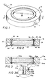
- an embodiment of a drop dispensing device in accordance with the present invention is generally designated by the reference numeral 10.
- the device 10 includes a pair of concentric circular ring members 12 and 14 which provide a sealed annular chamber 16 to which a supply of fluid, such as ink, is connected by an inlet conduit 18.
- a nozzle 20 opens to the annular chamber 16 and is spaced circumferentially from the conduit 18.
- the inlet conduit 18 and the nozzle 20 are located to be diammetrically opposite from each other on the outer ring 12 but other angular relationships of the conduit and nozzle may be used.
- a circular piezoelectric actuator disk 22 is supported concentrically from the inner disk 14 in a manner to be described in more detail below.
- the drop dispenser 10 has an outer diameter of approximately 10 mm (.4 inches) and an axial length or height approximating 2.5 mm (.1 inches).
- outer diameter approximately 10 mm (.4 inches) and an axial length or height approximating 2.5 mm (.1 inches).
- both the outer and inner rings 12 and 14, respectively, are formed of plastic materials selected to provide flexibility in the inner ring 14 and rigidity in the outer ring 12. While specific plastic material candidates will vary depending on the characteristics of the fluid to be dispensed in drop form by the device 10, the outer ring 12 is formed preferably by injection molding a high flexural modulus material such as carbon filled nylon.
- the plastic inner ring 14, on the other hand, may be formed either entirely by injection molding of Delrin (registered trade mark) or in part by injection molding and in part by machining the same material.
- the outer ring 12 is essentially rectangular in annular cross-section to establish an outer cylindrical surface 24, a concentric and single inner cylindrical surface 26 and a pair of end faces 28 and 30.
- a chamfer 32 is provided between the end face 28 and the inner cylindrical surface 26.
- the outside diameter of the outer ring 12 or the diameter of the outer cylindrical surface 24 is 10 mm (.400 inches)
- the inside diameter of the inner cylindrical surface 26 is 7.2 mm (.285 inches) to provide a radial thickness of 1.5mm (.0575 inches).
- the height of the outer ring is the same as the overall height of the drop dispensing device 10 and may vary from 2.5 mm (.100 inches) to 3.8 mm (.150 inches).
- the inner ring 14 has a discontinuous outer cylindrical surface 34, an inner cylindrical surface 36 and a pair of end faces 38 and 40 spaced by an axial distance to provide a length in the inner ring 14 the same as the length of the outer ring 12.
- the surface 34 is interrupted centrally by a peripheral groove 42 in the inner ring 14.
- the annular chamber 16, therefore, is defined completely by the peripheral groove 42 in the inner ring 14.
- the groove 42 and the inner surface 36 of the inner ring 14 define a relatively thin flexible wall 44 of an axial length equal to the width of the peripheral groove 42.
- the axial length of the flexible wall 44 is, moreover, substantially the same as the thickness or axial length of the piezoelectric actuator disk 22.
- the plastic inner ring 14 of the device 10 in the embodiments of Figs. 1 and 2 is dimensioned so that the diameter of the discontinuous outer cylindrical surface sections 34 are between 7.27 mm (.2865 inches) and 7.28 mm (.287 inches).
- the outside diameter of the inner ring 14 exceeds the inside diameter of the outer ring by a dimensional increase of between 0.025 mm (.001 inches) and 0.05 mm (.002 inches).
- this diameter differential between the effective outside periphery of the inner ring and the inside diameter of the outer ring enables the two rings to be assembled by press fit alone while insuring a fluid tight closure about the annular chamber 16.
- the inside diameter of the inner ring 14 at the surface 36 approximates 69 mm (.272 inches) to provide a radial thickness approximating 0.38 mm (.015 inches) in the inner ring portions lying axially outside the groove 42.
- the depth of the groove 42 is selected primarily to leave a radial thickness of between 0.076 mm (.003 inches) and 0.127 mm (.005 inches) in the flexible wall 44.
- annular chamber 16a is defined entirely by an inner peripheral groove 42a in the outer ring 12a.
- the inner ring 14a in this instance, is formed as a thin metallic ring having continuous inner and outer cylindrical surfaces 34a and 36a to establish, respectively, the outside and inside diameters of the ring 14a.
- a chamfer 32a is provided between the bottom edge 40a and the outer cylindrical surface 34a.
- the outer ring 12a of the device 10a is dimensioned so that the radial thickness between the base of the groove 42a and the outer cylindrical surface 24a is essentially the same as the corresponding dimension in the embodiment previously described with reference to Figs. 1 and 2.
- the inner diameter at the cylindrical surface 22a, which is discontinuous, is smaller than in the previous embodiment by the depth of the groove 42a.
- the radial thickness of the inner ring 14a in the embodiment of Fig. 3 is approximately 0.076 mm (.003 inches) to assure flexure in response to excitation of the piezoelectric actuator 22a.
- Such metals as nickel or stainless steel may be used to form the inner ring 14a. While stainless steel is preferred from the standpoint of lower cost, nickel is equally resistant to corrosion by fluids to be dispensed and in addition, is more resistant to metal fatigue.
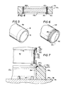
- FIG. 4 a still further embodiment of the invention is illustrated in which the letter suffix "c" is used with reference numerals to identify parts corresponding to those previously identified in the embodiments of Figs. 1-3.
- the embodiment of Fig. 4 is like the embodiment of Figs. 1 and 2 in the sense that the outer ring 12c is essentially the same as the outer ring 12 employed in the embodiment of Fig. 2.
- the inner ring 14c of the device 10c however, like the embodiment of Fig. 3, is formed of nickel or stainless steel and is machined to define the outer peripheral groove 42c for establishing the chamber 16c like the embodiment of Fig. 2.
- peripheral groove 42 is formed in a metallic ring such as the ring 14c or in a plastic ring such as the ring 14 in the embodiment of Fig. 2.
- the apparatus includes a stepped mandrel 50 having a working end portion 52 of a diameter smaller than the diameter of the body of the mandrel 50 to establish a peripheral abutment shoulder 54.
- an anvil 56 having a planar top surface 58 is provided to support the outer ring 12c.
- the anvil further includes a plurality of upwardly projecting actuator supporting pins 60 to facilitate assembly of the piezoelectric actuator 22c with the rings 12c and 14c in a manner to be described.
- the mandrel 52 is shown with an inner ring blank B mounted thereon.
- the mandrel 50 may be a preformed mandrel to which the ring blank B is fitted by interference fit or by a releasable adhesive.
- the mandrel 50 may be formed of etchable material such as aluminum on which the ring blank B is formed directly on the mandrel by electrodeposition or similar processes.
- the blank B Upon being supported on the working end 52 of the mandrel 50, the blank B is machined by honing or other such abrading processes to form the peripheral groove 42c by rotation of the mandrel 50 and application of a honing tool (not shown). Also during this machining process, particularly in the case of the ring 14c of the embodiment of Fig. 4, sharp corners such as those at the junction of end 40c and the outer cylindrical surface 34c (Fig 7) of the ring 14c as well as the corner between the groove 42c and the upper portion of the outer cylindrical surface 34c would be rounded or at least softened to eliminate cutting edges.
- the outer ring 12c is positioned on the anvil 56 as shown in Fig. 7 and the assembly of the mandrel and the formed inner ring 14c forced downwardly into the outer ring 12c to the position represented by phantom lines in Fig. 7.
- the chamfer 32c on the outer ring 32 will facilitate the press fit of the inner ring 14c within the outer ring 12c.
- the softening of sharp edges on the metallic ring 14c in this instance will augment the needed expansion of the outer ring and/or compression of the inner ring to accommodate the diameter differential D d of between 0.025 and 0.05 mm (.001 and .002 inches) as above described.
- the mandrel 50 is removed from the inner ring either by retaining the outer ring 12c while withdrawing the mandrel if the blank B is mounted by interference fit, for example or by etching away the end portion 52 of the mandrel to leave open the central portion of the inner ring 14c.
- a fluid-tight seal about the annular chamber 16 is maintained between the inner and outer rings exclusively by inner/outer peripheral surface contact and hoop stress in the rings.
- the piezoelectric actuator 22c is dropped in place onto the locating pins 60.
- the piezoelectric actuator in all embodiments is of a diameter which is less than the inside diameter of the inner ring 14 so that there will be no interference with insertion of the actuator 22.
- the annular space between the outer periphery of the actuator 22c and the inner surface 36 of the inner ring 14 is filled with an epoxy E to bond the actuator 22c in place.
- the epoxy E functions as an adhesive to retain the actuator in the assembled drop dispensing device and to transmit peripherally directed force from the actuator to the flexible wall 44 in all embodiments.
- the epoxy functions to electrically insulate the piezoelectric actuator from the inner ring.
- the epoxy operates as a compressive medium to transmit radial dimension changes in the actuator 22 when excited electrically to reduce the volume of the annular chamber 16.
- the present invention provides a highly effective drop dispensing device and method for its manufacture by which the above objects, among others, are fulfilled.
Landscapes
- Engineering & Computer Science (AREA)
- Manufacturing & Machinery (AREA)
- Coating Apparatus (AREA)
- Confectionery (AREA)
- Making Paper Articles (AREA)
- Transition And Organic Metals Composition Catalysts For Addition Polymerization (AREA)
- Pharmaceuticals Containing Other Organic And Inorganic Compounds (AREA)
- Telephone Function (AREA)
- Particle Formation And Scattering Control In Inkjet Printers (AREA)
Claims (14)
- Dispositif de distribution de gouttes comportant un actionneur électrique de forme plane entouré par une surface périphériquement circonférentielle pour appliquer une force dirigée périphériquement en réponse à une excitation électrique, un moyen comprenant des bagues intérieure et extérieure concentriques pour définir une chambre annulaire autour de ladite surface circonférentielle, et des moyens formant une admission de fluide et un orifice de sortie de fluide en communication avec la chambre annulaire pour distribuer une goutte de fluide lors de l'excitation électrique de l'actionneur électrique, le dispositif comprenant :
un moyen assurant un contact périphérique entre les bagues et une contrainte de frettage dans ces dernières pour retenir les bagues intérieure et extérieure dans une disposition mutuelle étanche aux fluides autour de la chambre annulaire. - Dispositif de distribution de gouttes selon la revendication 1, dans lequel la chambre annulaire est formée par une rainure périphérique dans l'une des bagues intérieure et extérieure.
- Dispositif distributeur de gouttes selon la revendication 2, dans lequel la bague intérieure est formée d'une matière plastique flexible.
- Dispositif distributeur de gouttes selon la revendication 2, dans lequel la bague intérieure est formée d'un métal.
- Dispositif distributeur de gouttes selon la revendication 4, dans lequel la bague intérieure est formée d'acier inoxydable.
- Dispositif distributeur de gouttes selon la revendication 4, dans lequel la bague intérieure est formée de nickel.
- Dispositif distributeur de gouttes selon la revendication 2, dans lequel la rainure délimite une paroi flexible de longueur axiale prédéterminée dans la bague intérieure.
- Dispositif distributeur de gouttes selon la revendication 7, dans lequel l'épaisseur de la paroi flexible est comprise entre 0,05 et 0,2 mm (0,002 et 0,008 inch).
- Dispositif distributeur de gouttes selon la revendication 7, dans lequel la longueur axiale de la paroi flexible est sensiblement égale à la dimension axiale de l'actionneur électrique.
- Dispositif distributeur de gouttes selon l'une quelconque des revendications 7, 8 ou 9, comprenant un anneau d'époxy pour fixer l'actionneur électrique à la surface intérieure de la paroi flexible.
- Dispositif distributeur de gouttes selon la revendication 2, dans lequel la bague extérieure comprend une surface cylindrique continue, la bague intérieure comportant ladite rainure dans sa surface circonférentielle extérieure.
- Procédé pour former un dispositif distributeur de gouttes comportant un actionneur électrique de forme plane entouré par une surface périphériquement circonférentielle pour appliquer une force dirigée périphériquement en réponse à une excitation électrique, un moyen comprenant des bagues intérieure et extérieure concentriques pour former une chambre annulaire autour de la surface circonférentielle, et un moyen formant un orifice d'entrée de fluide et un orifice de sortie de fluide communiquant avec la chambre annulaire pour distribuer une goutte de fluide lors de l'excitation électrique de l'actionneur électrique, le procédé susvisé comprenant les étapes consistant :
à donner à la bague intérieure un diamètre extérieur légèrement plus grand que le diamètre intérieur de la bague extérieure ; et
à emboîter de force la bague intérieure dans la bague extérieure pour rendre étanche la chambre annulaire exclusivement par un contact de surface entre les bagues intérieure et extérieure et par une contrainte de frettage dans ces bagues intérieure et extérieure. - Procédé selon la revendication 12, dans lequel le diamètre extérieur de la bague intérieur dépasse le diamètre intérieur de la bague extérieure d'une quantité comprise entre 0,025 et 0,05 mm (0,001 et 0,002 inch).
- Procédé selon la revendication 12, comprenant l'étape consistant à coller l'actionneur électrique à la bague intérieure à l'aide d'un adhésif transmettant une compression.
Priority Applications (1)
| Application Number | Priority Date | Filing Date | Title |
|---|---|---|---|
| AT87890187T ATE78755T1 (de) | 1986-09-15 | 1987-08-11 | Troepfchenabgabevorrichtung und verfahren zu ihrer herstellung. |
Applications Claiming Priority (2)
| Application Number | Priority Date | Filing Date | Title |
|---|---|---|---|
| US06/906,978 US4692776A (en) | 1986-09-15 | 1986-09-15 | Drop dispensing device and method for its manufacture |
| US906978 | 1986-09-15 |
Publications (3)
| Publication Number | Publication Date |
|---|---|
| EP0262115A2 EP0262115A2 (fr) | 1988-03-30 |
| EP0262115A3 EP0262115A3 (en) | 1989-03-08 |
| EP0262115B1 true EP0262115B1 (fr) | 1992-07-29 |
Family
ID=25423334
Family Applications (1)
| Application Number | Title | Priority Date | Filing Date |
|---|---|---|---|
| EP87890187A Expired - Lifetime EP0262115B1 (fr) | 1986-09-15 | 1987-08-11 | Dispositif débiteur de gouttelettes et son procédé de fabrication |
Country Status (7)
| Country | Link |
|---|---|
| US (1) | US4692776A (fr) |
| EP (1) | EP0262115B1 (fr) |
| JP (1) | JPS6377747A (fr) |
| AT (1) | ATE78755T1 (fr) |
| AU (1) | AU588208B2 (fr) |
| CA (1) | CA1284284C (fr) |
| DE (2) | DE262115T1 (fr) |
Families Citing this family (1)
| Publication number | Priority date | Publication date | Assignee | Title |
|---|---|---|---|---|
| US10035245B2 (en) | 2012-04-30 | 2018-07-31 | Eigen Systems Limited | Clamp foot air jet apparatus |
Family Cites Families (25)
| Publication number | Priority date | Publication date | Assignee | Title |
|---|---|---|---|---|
| US3281860A (en) * | 1964-11-09 | 1966-10-25 | Dick Co Ab | Ink jet nozzle |
| SE349676B (fr) * | 1971-01-11 | 1972-10-02 | N Stemme | |
| US3965376A (en) * | 1973-02-07 | 1976-06-22 | Gould Inc. | Pulsed droplet ejecting system |
| US3852773A (en) * | 1973-03-08 | 1974-12-03 | Olympia Werke Ag | Ink ejection printing devices |
| US4068144A (en) * | 1976-09-20 | 1978-01-10 | Recognition Equipment Incorporated | Liquid jet modulator with piezoelectric hemispheral transducer |
| CA1107800A (fr) * | 1976-10-12 | 1981-08-25 | Kenneth H. Fischbeck | Formation de gouttelettes par coincidence d'impulsions de debit et de vitesse du fluide |
| US4131899A (en) * | 1977-02-22 | 1978-12-26 | Burroughs Corporation | Droplet generator for an ink jet printer |
| US4303927A (en) * | 1977-03-23 | 1981-12-01 | International Business Machines Corporation | Apparatus for exciting an array of ink jet nozzles and method of forming |
| US4245227A (en) * | 1978-11-08 | 1981-01-13 | International Business Machines Corporation | Ink jet head having an outer wall of ink cavity of piezoelectric material |
| JPS5644671A (en) * | 1979-09-21 | 1981-04-23 | Seiko Epson Corp | Ink-jet head |
| US4353078A (en) * | 1979-09-24 | 1982-10-05 | International Business Machines Corporation | Ink jet print head having dynamic impedance adjustment |
| FR2488150B1 (fr) * | 1980-08-08 | 1986-04-04 | Bertin & Cie | Dispositif d'ejection de gouttelettes a la demande |
| JPS5789971A (en) * | 1980-11-26 | 1982-06-04 | Hitachi Ltd | Ink jet recorder |
| JPS57131567A (en) * | 1981-01-16 | 1982-08-14 | Ricoh Co Ltd | Nozzle for ink jet printer |
| US4459601A (en) * | 1981-01-30 | 1984-07-10 | Exxon Research And Engineering Co. | Ink jet method and apparatus |
| IT1144294B (it) * | 1981-07-10 | 1986-10-29 | Olivetti & Co Spa | Dispositivo di stampa getto selettivo d inchiostro |
| US4387383A (en) * | 1981-11-12 | 1983-06-07 | Ncr Corporation | Multiple nozzle ink jet print head |
| US4449135A (en) * | 1981-12-23 | 1984-05-15 | Ricoh Company, Ltd. | Ink ejection head |
| JPS58220758A (ja) * | 1982-06-16 | 1983-12-22 | Matsushita Electric Ind Co Ltd | インクジエツト記録装置 |
| JPS5912775A (ja) * | 1982-07-14 | 1984-01-23 | Matsushita Electric Ind Co Ltd | 霧化ポンプユニツト |
| US4516140A (en) * | 1983-12-27 | 1985-05-07 | At&T Teletype Corporation | Print head actuator for an ink jet printer |
| US4528571A (en) * | 1984-03-05 | 1985-07-09 | The Mead Corporation | Fluid jet print head having baffle means therefor |
| US4550325A (en) * | 1984-12-26 | 1985-10-29 | Polaroid Corporation | Drop dispensing device |
| US4641155A (en) * | 1985-08-02 | 1987-02-03 | Advanced Color Technology Inc | Printing head for ink jet printer |
| US4625373A (en) * | 1985-08-02 | 1986-12-02 | Advanced Color Technology, Inc. | Method of making a printing head for an ink jet printer |
-
1986
- 1986-09-15 US US06/906,978 patent/US4692776A/en not_active Expired - Fee Related
-
1987
- 1987-07-15 CA CA000542148A patent/CA1284284C/fr not_active Expired - Fee Related
- 1987-08-11 EP EP87890187A patent/EP0262115B1/fr not_active Expired - Lifetime
- 1987-08-11 AT AT87890187T patent/ATE78755T1/de not_active IP Right Cessation
- 1987-08-11 DE DE198787890187T patent/DE262115T1/de active Pending
- 1987-08-11 DE DE8787890187T patent/DE3780740T2/de not_active Expired - Fee Related
- 1987-08-20 AU AU77251/87A patent/AU588208B2/en not_active Ceased
- 1987-08-24 JP JP62208403A patent/JPS6377747A/ja active Pending
Also Published As
| Publication number | Publication date |
|---|---|
| DE262115T1 (de) | 1988-07-21 |
| CA1284284C (fr) | 1991-05-21 |
| DE3780740D1 (de) | 1992-09-03 |
| US4692776A (en) | 1987-09-08 |
| EP0262115A3 (en) | 1989-03-08 |
| DE3780740T2 (de) | 1993-01-21 |
| ATE78755T1 (de) | 1992-08-15 |
| AU7725187A (en) | 1988-03-17 |
| EP0262115A2 (fr) | 1988-03-30 |
| AU588208B2 (en) | 1989-09-07 |
| JPS6377747A (ja) | 1988-04-07 |
Similar Documents
| Publication | Publication Date | Title |
|---|---|---|
| JP4382097B2 (ja) | 流体部品をクランプする装置 | |
| US20170146030A1 (en) | Method of manufacturing centrifugal pump | |
| EP0262115B1 (fr) | Dispositif débiteur de gouttelettes et son procédé de fabrication | |
| US5154356A (en) | Aerosol nozzle assembly and method of making the same | |
| JP3620316B2 (ja) | マイクロポンプとその製造方法 | |
| JPH04227859A (ja) | 吸引装置 | |
| US6968723B2 (en) | Method of punching small hole and method of manufacturing liquid ejection head using the same | |
| JPH06313481A (ja) | ショックアブソーバのピストン | |
| US7100415B2 (en) | Method and apparatus for manufacturing a liquid ejection head | |
| EP1080841A3 (fr) | Tête de support, dispositif de polissage utilisant la tête, et procédé permettant de déceler l'état de la surface polie | |
| JPS6127247B2 (fr) | ||
| KR970704974A (ko) | 등속조인트의 외륜과 축의 접합구조 | |
| US4544932A (en) | Ink jet apparatus and method of making the apparatus | |
| US5468128A (en) | Sealed piston pump | |
| US4480983A (en) | Collet and method for dispensing viscous materials | |
| US7363795B2 (en) | Guided punching apparatus | |
| JP2003042307A (ja) | メカニカルシール及びその組立方法 | |
| JP4043809B2 (ja) | モータ | |
| CN115501988A (zh) | 流体筒及用于消除喷射头芯片上的机械应力的方法 | |
| JPS59142969A (ja) | 弁取付け杯状体 | |
| US4141181A (en) | Holding disk for a boreless grinding wheel | |
| EP0791469B1 (fr) | Collecteur d'encre cylindrique | |
| JPH0538864Y2 (fr) | ||
| US5146084A (en) | Rotary code disk mounting structure for an optical encoder with an adhesive substance filling the circular recess of the spindle for adherence to said disk | |
| JPH02124256A (ja) | 光学素子の研磨用保持装置 |
Legal Events
| Date | Code | Title | Description |
|---|---|---|---|
| PUAI | Public reference made under article 153(3) epc to a published international application that has entered the european phase |
Free format text: ORIGINAL CODE: 0009012 |
|
| AK | Designated contracting states |
Kind code of ref document: A2 Designated state(s): AT CH DE FR GB IT LI NL |
|
| ITCL | It: translation for ep claims filed |
Representative=s name: RICCARDI SERGIO & CO. |
|
| TCAT | At: translation of patent claims filed | ||
| TCNL | Nl: translation of patent claims filed | ||
| EL | Fr: translation of claims filed | ||
| DET | De: translation of patent claims | ||
| PUAL | Search report despatched |
Free format text: ORIGINAL CODE: 0009013 |
|
| AK | Designated contracting states |
Kind code of ref document: A3 Designated state(s): AT CH DE FR GB IT LI NL |
|
| 17P | Request for examination filed |
Effective date: 19890825 |
|
| 17Q | First examination report despatched |
Effective date: 19910516 |
|
| GRAA | (expected) grant |
Free format text: ORIGINAL CODE: 0009210 |
|
| AK | Designated contracting states |
Kind code of ref document: B1 Designated state(s): AT CH DE FR GB IT LI NL |
|
| PG25 | Lapsed in a contracting state [announced via postgrant information from national office to epo] |
Ref country code: IT Free format text: LAPSE BECAUSE OF FAILURE TO SUBMIT A TRANSLATION OF THE DESCRIPTION OR TO PAY THE FEE WITHIN THE PRESCRIBED TIME-LIMIT;WARNING: LAPSES OF ITALIAN PATENTS WITH EFFECTIVE DATE BEFORE 2007 MAY HAVE OCCURRED AT ANY TIME BEFORE 2007. THE CORRECT EFFECTIVE DATE MAY BE DIFFERENT FROM THE ONE RECORDED. Effective date: 19920729 Ref country code: NL Effective date: 19920729 Ref country code: LI Effective date: 19920729 Ref country code: CH Effective date: 19920729 Ref country code: AT Effective date: 19920729 |
|
| REF | Corresponds to: |
Ref document number: 78755 Country of ref document: AT Date of ref document: 19920815 Kind code of ref document: T |
|
| ET | Fr: translation filed | ||
| REF | Corresponds to: |
Ref document number: 3780740 Country of ref document: DE Date of ref document: 19920903 |
|
| REG | Reference to a national code |
Ref country code: CH Ref legal event code: PL |
|
| NLV1 | Nl: lapsed or annulled due to failure to fulfill the requirements of art. 29p and 29m of the patents act | ||
| PLBE | No opposition filed within time limit |
Free format text: ORIGINAL CODE: 0009261 |
|
| STAA | Information on the status of an ep patent application or granted ep patent |
Free format text: STATUS: NO OPPOSITION FILED WITHIN TIME LIMIT |
|
| 26N | No opposition filed | ||
| PGFP | Annual fee paid to national office [announced via postgrant information from national office to epo] |
Ref country code: FR Payment date: 19940711 Year of fee payment: 8 |
|
| PGFP | Annual fee paid to national office [announced via postgrant information from national office to epo] |
Ref country code: GB Payment date: 19940715 Year of fee payment: 8 |
|
| PGFP | Annual fee paid to national office [announced via postgrant information from national office to epo] |
Ref country code: DE Payment date: 19940720 Year of fee payment: 8 |
|
| PG25 | Lapsed in a contracting state [announced via postgrant information from national office to epo] |
Ref country code: GB Effective date: 19950811 |
|
| GBPC | Gb: european patent ceased through non-payment of renewal fee |
Effective date: 19950811 |
|
| PG25 | Lapsed in a contracting state [announced via postgrant information from national office to epo] |
Ref country code: FR Effective date: 19960430 |
|
| PG25 | Lapsed in a contracting state [announced via postgrant information from national office to epo] |
Ref country code: DE Effective date: 19960501 |
|
| REG | Reference to a national code |
Ref country code: FR Ref legal event code: ST |