EP0261907A2 - Fenêtre - Google Patents
Fenêtre Download PDFInfo
- Publication number
- EP0261907A2 EP0261907A2 EP87308325A EP87308325A EP0261907A2 EP 0261907 A2 EP0261907 A2 EP 0261907A2 EP 87308325 A EP87308325 A EP 87308325A EP 87308325 A EP87308325 A EP 87308325A EP 0261907 A2 EP0261907 A2 EP 0261907A2
- Authority
- EP
- European Patent Office
- Prior art keywords
- parts
- fenestration system
- formations
- cladding panels
- affixment
- Prior art date
- Legal status (The legal status is an assumption and is not a legal conclusion. Google has not performed a legal analysis and makes no representation as to the accuracy of the status listed.)
- Withdrawn
Links
Images


Classifications
-
- E—FIXED CONSTRUCTIONS
- E06—DOORS, WINDOWS, SHUTTERS, OR ROLLER BLINDS IN GENERAL; LADDERS
- E06B—FIXED OR MOVABLE CLOSURES FOR OPENINGS IN BUILDINGS, VEHICLES, FENCES OR LIKE ENCLOSURES IN GENERAL, e.g. DOORS, WINDOWS, BLINDS, GATES
- E06B1/00—Border constructions of openings in walls, floors, or ceilings; Frames to be rigidly mounted in such openings
- E06B1/62—Tightening or covering joints between the border of openings and the frame or between contiguous frames
-
- E—FIXED CONSTRUCTIONS
- E06—DOORS, WINDOWS, SHUTTERS, OR ROLLER BLINDS IN GENERAL; LADDERS
- E06B—FIXED OR MOVABLE CLOSURES FOR OPENINGS IN BUILDINGS, VEHICLES, FENCES OR LIKE ENCLOSURES IN GENERAL, e.g. DOORS, WINDOWS, BLINDS, GATES
- E06B1/00—Border constructions of openings in walls, floors, or ceilings; Frames to be rigidly mounted in such openings
- E06B1/02—Base frames, i.e. template frames for openings in walls or the like, provided with means for securing a further rigidly-mounted frame; Special adaptations of frames to be fixed therein
-
- E—FIXED CONSTRUCTIONS
- E06—DOORS, WINDOWS, SHUTTERS, OR ROLLER BLINDS IN GENERAL; LADDERS
- E06B—FIXED OR MOVABLE CLOSURES FOR OPENINGS IN BUILDINGS, VEHICLES, FENCES OR LIKE ENCLOSURES IN GENERAL, e.g. DOORS, WINDOWS, BLINDS, GATES
- E06B1/00—Border constructions of openings in walls, floors, or ceilings; Frames to be rigidly mounted in such openings
- E06B1/04—Frames for doors, windows, or the like to be fixed in openings
- E06B1/32—Frames composed of parts made of different materials
- E06B1/325—Frames composed of parts made of different materials comprising insulation between two metal section members
-
- E—FIXED CONSTRUCTIONS
- E06—DOORS, WINDOWS, SHUTTERS, OR ROLLER BLINDS IN GENERAL; LADDERS
- E06B—FIXED OR MOVABLE CLOSURES FOR OPENINGS IN BUILDINGS, VEHICLES, FENCES OR LIKE ENCLOSURES IN GENERAL, e.g. DOORS, WINDOWS, BLINDS, GATES
- E06B1/00—Border constructions of openings in walls, floors, or ceilings; Frames to be rigidly mounted in such openings
- E06B1/56—Fastening frames to the border of openings or to similar contiguous frames
- E06B1/60—Fastening frames to the border of openings or to similar contiguous frames by mechanical means, e.g. anchoring means
Definitions
- This invention relates to fenestration of structures clad with panels.
- apertures formed or left in cladding panels at installation are trimmed off so as to be capable of glazing directly, such trimming off comprising cooperating first and second parts, the first parts fixing by one surface to one side (usually inner) of the cladding and presenting an affixment surface, whether extending parallel with or away from the cladding about a window aperture, and the second parts fixing by first surfaces to said affixment surfaces of the first parts and extending therefrom into the window aperture over the thickness of the cladding.
- first parts we refer to the first parts as “framing members”, and to the second parts as “glazing extrusions”, though it will be appreciated that the latter may be not only directly glazed but alternatively be employed in relation to fitting of window units, i.e. by applicable both to glass or glass units (e.g. double glazed modules) and to frames of windows having opening lights.
- the framing members will normally be themselves fixed to structural steelwork of the building (wall) concerned, may even be part of at least secondary such steelwork.
- the framing members can be of simple angle form mitred together about the cladding aperture with their one surfaces at least overlapping onto the side of the cladding to which they fix. Then, the affixment surfaces may be on a surface of the angle form that extends away from the cladding aperture, but could alternatively be on said one surface but inside the cladding aperture.
- Other forms of framing member could, of course, be used, for example of channel form with the web affording said one surfaces, or of box section.
- the glazing extrusions preferably have their first surfaces to affix to said affixment surfaces of the framing members extending towards or stepped towards inner edges of the cladding aperture from where they extend thereinto, which extension is conveniently from a hollow box formation of the glazing extrusion that is preferably shallow in its extension over the cladding thickness.
- Such provisions particularly facilitate both of neat packing relative to said affixment of the framing members, and of sealing provision between the box formation and edges of the cladding panels or flashing system between those edges and the provisions hereof.
- the glazing extrusions present spaced limbs with confronting seal housing formations for glass sheets etc and it is preferred that at least one of said limbs (usually the outer) have compliance relative to the glazing extrusions as affixed to said affixing surfaces of the framing members.
- said limbs usually the outer
- cappings extend onto the other side of the cladding, otherwise into the cladding aperture onto an inset or rebate formation normally contributing to panel interfitting or onto a further extrusion under the framing member, in all cases preferably with a seal-housing formation relative thereto.
- first and second component extrusions having formations for interconnecting attachment by way of heat insulating resilient material then providing both said compliance and a thermal barrier.
- the aforesaid other limb is preferably provided by a third glazing extrusion affixing to the first glazing extrusion, further preferably via a formation at or near the side of its hollow box formation coincident with said extension.
- the last-mentioned formation is utilised in mounting of frame of window units with opening lights.
- systems hereof can provide partitioning of such apertures via mullion extrusions, conveniently of hollow box formations which can further afford location for said third glazing extrusions at one side and a transverse extrusion at the other side as spaced confronting glazing limbs.
- an aperture 10 in a cladding panel or panels 12 is shown trimmed off using framing members 13 of angle formation applied, conveniently screwed, at one surface 13A to the inside of the cladding and presenting another surface 13B extending away from that side for affixment of glazing extrusions.
- Composite glazing extrusions (14) are applied, conveniently screwed, at first surfaces 14X to the other surfaces 13B of the framing members, see also packings 15 and seals 16A, 16B.
- the surfaces 14X are shown stepped to 14Y at extension into the thickness of the aperture 10.
- the framing members 12 and associated glazing extrusions 14 are shown applied over flashing provisions 16, comprised of right angle formed jamb flashings 16J, obtuse-angle formed head flashing 16H, and at least slightly sloping cill flashing 16C.
- Figures 2 and 3 show jointing of such flashings, which will usually be butt-welded at end edges.
- the stepped glazing extrusion surface 14X, Y is shown of a first component extrusion 14A having a formation 14F by whcih it retainingly engages an extrusion of resilient heat insulating material 17.
- the formation 14F is on a hollow box formation 14S that is shallow in the direction of the thickness of the cladding 12 and is oppositely bounded by the surface 14Y and a surface 14Z within which a glazing unit 20 is installed.
- the glazing formations 14 of Figures 1 to 4 are shown affording spaced limbs with confronting housing formations 18A, 18B for seals 18S, 18D to a glazing unit 20 shown as of double sheet type on setting blocks 21 at its lower edge.
- the seal housing formation 18B is on a second glazing component extrusion 14B connected to the first component extrusion 14A by retaining engagement at 14G with the heat insulating material extrusion 17.
- the second component extrusion 14B extends generally transversely of the first component extrusion 14A, and the thermal barrier extrusion 17 affords a degree of compliance between them.
- the seal housing formation 18A is on a third glazing component extrusion fitting to the first component extrusion 14A via cooperating formations at 14M and 14N.
- the first and second glazing component extrusions 14A, 14B have further formations by which they retainingly accommodate snap-fitting cappings 22, 24 over the position of fitting the first extrusion 14A to the frame member 12 and over the second extrusion 14B, respectively.
- the capping 24 further extends to a seal housing formation 24C onto the outer side of the cladding panels 12.
- Location blocks 26H, J and C are shown about the glazing extrusion system 14 at top sides and bottom for location relative to the aforementioned flashing system 16.
- Figure 1 shows cladding panels 12 cut or end-spaced to form the aperture 10, i.e. with square edges to that aperture.
- Figure 4 shows normally interfitting formations 12A and 12B (part only) of the panels 12, i.e. with the panels installed for interfitment vertically and with the aperture 10 assumed to be of a width substantially corresponding to widths, or at least glazing spacing, of the panels 12, though a tongue has been cut from the formation 12B.
- Figure 4 also shows a mullion glazing extrusion 26 with a variant indicated dashed at 26 ⁇ to allow a choice of depth of mullion to suit span or loading conditions.
- a basic hollow box section has formations 26A, 26B similar to above-mentioned formations 14M for cooperation with glazing component extrusions similar to those shown at 14C, hence again labelled 14C.
- the outside of the mullion extrusion 26 has a compliant fixing to a capping extrusion 26C shown via a thermal break extrusion 28.
- Figures 5 and 6 show a modified embodiment for use where the cladding panels 12 interfit normally with each other at horizontal adjacency of their formed edges 12C, 12D.
- Figure 5 shows such interfitting formations and modified exterior cappings 24 ⁇ that return to seal housing formations bearing onto a rebate of the panel edge 12D and into a further extrusion 14D of the glazing system that has a hooked edge 14H fitting into a groove of the panel edge 12C.
- the framing members are shown bolted onto the rebate and the further extrusion, a clip 30 being used at the former.
- an extruded resilient gasket 32 is used for sealing purposes. It will be appreciated that these fixing measures permit fitting without the flashing system 16 of Figures 1 to 4, and related measures could be employed for replacing the flashing system 16 of those Figures, if desired.
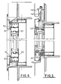
- Figure 7 shows a way of jointing glazed units against a structural member 40, using a suitable extrusion 41 and site applied sealing beads 42 and tape 43.
- Figure 8 is a partial section through a cladding aperture glazed with an inwardly opening light.
- the third glazing component extrusion 14C of Figures 1 to 6 is omitted, and typical opening light frame extrusions 50 are indicated in thick black lines, together with suitable sealing arrangements 51, 52. Otherwise, the system is similar to that of Figures 1 to 4.
- Figure 9 shows a similar section through an outwardly-opening frame, again similar to Figures 1 to 4, but this time with a subframe 60 between the limbs 15A, 15B.
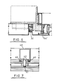
- Figure 10 shows an outwardly opening light that includes a thermally broken subframe composed of two extrusions 70A, 70B connected by thermal barrier extrusions 71, and an opening frame also of two extrusions 72A, 72B connected by a thermal barrier extrusion 73.
- the formations for seal housing at 14G and for the third panel extrusion at 14M are shown used for the subframe extrusions.
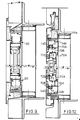
- Figures 11, 12, and 13 show another embodiment in which the first glazing extrusions, some referenced 114A, have their first surfaces 114X for affixment to framing members 113 extend from box section 114S towards inner edges of the cladding aperture. Then, affixement to the framing members 113 is to extension of the same surface 113A as overlaps the cladding aperture. It will be appreciated that the structure shown in Figures 11, 12 and 13 is otherwise similar to that of Figures 5 and 6.
Landscapes
- Engineering & Computer Science (AREA)
- Civil Engineering (AREA)
- Structural Engineering (AREA)
- Mechanical Engineering (AREA)
- Securing Of Glass Panes Or The Like (AREA)
- Extrusion Moulding Of Plastics Or The Like (AREA)
Applications Claiming Priority (2)
| Application Number | Priority Date | Filing Date | Title |
|---|---|---|---|
| GB8622701 | 1986-09-20 | ||
| GB868622701A GB8622701D0 (en) | 1986-09-20 | 1986-09-20 | Fenestration system |
Publications (2)
| Publication Number | Publication Date |
|---|---|
| EP0261907A2 true EP0261907A2 (fr) | 1988-03-30 |
| EP0261907A3 EP0261907A3 (fr) | 1989-03-22 |
Family
ID=10604525
Family Applications (1)
| Application Number | Title | Priority Date | Filing Date |
|---|---|---|---|
| EP87308325A Withdrawn EP0261907A3 (fr) | 1986-09-20 | 1987-09-21 | Fenêtre |
Country Status (2)
| Country | Link |
|---|---|
| EP (1) | EP0261907A3 (fr) |
| GB (2) | GB8622701D0 (fr) |
Cited By (7)
| Publication number | Priority date | Publication date | Assignee | Title |
|---|---|---|---|---|
| DE4114850A1 (de) * | 1991-05-07 | 1992-11-12 | Kurt Mader | Rahmen fuer ein fenster, eine tuer oder fuer die auskleidung eines sonstigen wandungsausbruches in einem gebaeude, sowie dichtungsprofil fuer einen solchen rahmen |
| FR2723133A1 (fr) * | 1994-07-26 | 1996-02-02 | Haironville Sa | Dispositif d'habillage d'ouvertures de batiments, telles que des fenetres |
| DE19739727A1 (de) * | 1997-09-11 | 1999-03-18 | Joerg Berchthold | Verfahren zum Isolieren des Anschlußbereichs zwischen einem Glaselement und einem feststehenden Gebäudeteil |
| WO2001071142A1 (fr) * | 2000-03-22 | 2001-09-27 | Exterior Research And Design, L.L.C. | Joint de fenetre |
| US6668500B1 (en) * | 1999-05-26 | 2003-12-30 | Glasfabrik Lamberts Gmbh & Co. Kg | Holding rail for holding glass profile elements |
| WO2006121355A1 (fr) * | 2005-05-13 | 2006-11-16 | Hpj Holdings Limited | Ensemble de fenetrage |
| US7908796B2 (en) | 2005-05-13 | 2011-03-22 | Hpj Holdings Limited | Fenestration assembly |
Citations (4)
| Publication number | Priority date | Publication date | Assignee | Title |
|---|---|---|---|---|
| FR2294316A1 (fr) * | 1974-12-11 | 1976-07-09 | Koemmerling Kunststoff | Fenetre a caisson amortissant le bruit |
| DE2456220A1 (de) * | 1974-11-28 | 1976-08-12 | Kramer Aluminiumfenster Gmbh | Einbetoniertes fenster bzw. einbetonierte tuer |
| DE2630463A1 (de) * | 1976-07-07 | 1978-01-12 | Lechler Chemie Gmbh | Isolier- und dichtungsvorrichtung fuer fenster, tueren und dergleichen |
| FR2420012A1 (fr) * | 1978-03-16 | 1979-10-12 | Zilli Denis | Precadre de menuiserie metallique pour chassis coulissant ou chassis a la francaise |
-
1986
- 1986-09-20 GB GB868622701A patent/GB8622701D0/en active Pending
-
1987
- 1987-09-21 GB GB08722159A patent/GB2198176A/en not_active Withdrawn
- 1987-09-21 EP EP87308325A patent/EP0261907A3/fr not_active Withdrawn
Patent Citations (4)
| Publication number | Priority date | Publication date | Assignee | Title |
|---|---|---|---|---|
| DE2456220A1 (de) * | 1974-11-28 | 1976-08-12 | Kramer Aluminiumfenster Gmbh | Einbetoniertes fenster bzw. einbetonierte tuer |
| FR2294316A1 (fr) * | 1974-12-11 | 1976-07-09 | Koemmerling Kunststoff | Fenetre a caisson amortissant le bruit |
| DE2630463A1 (de) * | 1976-07-07 | 1978-01-12 | Lechler Chemie Gmbh | Isolier- und dichtungsvorrichtung fuer fenster, tueren und dergleichen |
| FR2420012A1 (fr) * | 1978-03-16 | 1979-10-12 | Zilli Denis | Precadre de menuiserie metallique pour chassis coulissant ou chassis a la francaise |
Cited By (9)
| Publication number | Priority date | Publication date | Assignee | Title |
|---|---|---|---|---|
| DE4114850A1 (de) * | 1991-05-07 | 1992-11-12 | Kurt Mader | Rahmen fuer ein fenster, eine tuer oder fuer die auskleidung eines sonstigen wandungsausbruches in einem gebaeude, sowie dichtungsprofil fuer einen solchen rahmen |
| FR2723133A1 (fr) * | 1994-07-26 | 1996-02-02 | Haironville Sa | Dispositif d'habillage d'ouvertures de batiments, telles que des fenetres |
| DE19739727A1 (de) * | 1997-09-11 | 1999-03-18 | Joerg Berchthold | Verfahren zum Isolieren des Anschlußbereichs zwischen einem Glaselement und einem feststehenden Gebäudeteil |
| US6668500B1 (en) * | 1999-05-26 | 2003-12-30 | Glasfabrik Lamberts Gmbh & Co. Kg | Holding rail for holding glass profile elements |
| WO2001071142A1 (fr) * | 2000-03-22 | 2001-09-27 | Exterior Research And Design, L.L.C. | Joint de fenetre |
| US6725610B2 (en) | 2000-03-22 | 2004-04-27 | Exterior Research, Llc | Window seal construction |
| WO2006121355A1 (fr) * | 2005-05-13 | 2006-11-16 | Hpj Holdings Limited | Ensemble de fenetrage |
| GB2441698A (en) * | 2005-05-13 | 2008-03-12 | Hpj Holdings Ltd | Fenestration assembly |
| US7908796B2 (en) | 2005-05-13 | 2011-03-22 | Hpj Holdings Limited | Fenestration assembly |
Also Published As
| Publication number | Publication date |
|---|---|
| GB2198176A (en) | 1988-06-08 |
| GB8722159D0 (en) | 1987-10-28 |
| GB8622701D0 (en) | 1986-10-29 |
| EP0261907A3 (fr) | 1989-03-22 |
Similar Documents
| Publication | Publication Date | Title |
|---|---|---|
| US4545161A (en) | Glazed curtain wall construction | |
| US3140763A (en) | Curtain wall | |
| EP2318634B1 (fr) | Membrane d'étanchéité pour étanchéifier les espaces entre des encadrements de fenêtre et des ouvertures brutes | |
| EP0102825A2 (fr) | Système de cloison démontable | |
| US4008552A (en) | Wall structure and elements therefor | |
| NZ507152A (en) | Wall cladding assembly with cladding having recesses along opposite sides to engage with flanges of support members | |
| US6088979A (en) | Frame for supporting an auxiliary glazing and method for installing the improved frame | |
| GB2133449A (en) | Panel mounting system | |
| EP0399778A1 (fr) | Mur rideau | |
| US4115964A (en) | Windows and method of making the same | |
| US4756132A (en) | External veneer cap for an existing wall framing system and method of installation | |
| EP0261907A2 (fr) | Fenêtre | |
| CA2227639C (fr) | Systeme d'ossature etanche pour la construction de batiments | |
| GB2212546A (en) | Fire-resistant mounting of panels | |
| US4270332A (en) | Windows and method of making the same | |
| NO890207L (no) | Festanordning for isolerglassruter i et yttervegg- eller takvindu. | |
| GB2142357A (en) | Curtain wall assembly | |
| US4715153A (en) | Panel mounting building wall construction | |
| GB2095318A (en) | Glazing or panelling system | |
| EP3725969A1 (fr) | Système de barrière de périmètre de feu | |
| GB2274866A (en) | Window or door frame structure | |
| US2731118A (en) | Means for mounting windows or other components in buildings | |
| GB2275718A (en) | Window or door construction | |
| EP3561189B1 (fr) | Paroi de séparation, en particulier pour la création d'un compartiment coupe-feu dans des salles de bâtiments | |
| JPH11324498A (ja) | 窓 |
Legal Events
| Date | Code | Title | Description |
|---|---|---|---|
| PUAI | Public reference made under article 153(3) epc to a published international application that has entered the european phase |
Free format text: ORIGINAL CODE: 0009012 |
|
| AK | Designated contracting states |
Kind code of ref document: A2 Designated state(s): AT BE CH DE ES FR GR IT LI LU NL SE |
|
| PUAL | Search report despatched |
Free format text: ORIGINAL CODE: 0009013 |
|
| AK | Designated contracting states |
Kind code of ref document: A3 Designated state(s): AT BE CH DE ES FR GR IT LI LU NL SE |
|
| 17P | Request for examination filed |
Effective date: 19891114 |
|
| STAA | Information on the status of an ep patent application or granted ep patent |
Free format text: STATUS: THE APPLICATION HAS BEEN WITHDRAWN |
|
| 18W | Application withdrawn |
Withdrawal date: 19900206 |