EP0261772B2 - Verfahren und Vorrichtung zur Beschichtung einer optischen Wellenleiterfaser - Google Patents
Verfahren und Vorrichtung zur Beschichtung einer optischen Wellenleiterfaser Download PDFInfo
- Publication number
- EP0261772B2 EP0261772B2 EP87306483A EP87306483A EP0261772B2 EP 0261772 B2 EP0261772 B2 EP 0261772B2 EP 87306483 A EP87306483 A EP 87306483A EP 87306483 A EP87306483 A EP 87306483A EP 0261772 B2 EP0261772 B2 EP 0261772B2
- Authority
- EP
- European Patent Office
- Prior art keywords
- fiber
- coating
- liquid
- die
- conditioning
- Prior art date
- Legal status (The legal status is an assumption and is not a legal conclusion. Google has not performed a legal analysis and makes no representation as to the accuracy of the status listed.)
- Expired - Lifetime
Links
- 238000000576 coating method Methods 0.000 title claims abstract description 172
- 239000011248 coating agent Substances 0.000 title claims abstract description 154
- 239000000835 fiber Substances 0.000 title claims abstract description 128
- 238000000034 method Methods 0.000 title claims abstract description 21
- 230000003287 optical effect Effects 0.000 title abstract description 16
- 239000007788 liquid Substances 0.000 claims abstract description 60
- 239000013307 optical fiber Substances 0.000 claims abstract description 47
- 239000000463 material Substances 0.000 claims abstract description 37
- 239000011521 glass Substances 0.000 claims abstract description 21
- 230000001681 protective effect Effects 0.000 claims abstract description 11
- 230000003750 conditioning effect Effects 0.000 claims description 31
- 230000002829 reductive effect Effects 0.000 claims description 5
- 238000010408 sweeping Methods 0.000 claims description 4
- 238000011144 upstream manufacturing Methods 0.000 claims description 4
- 239000003365 glass fiber Substances 0.000 claims description 3
- 238000007654 immersion Methods 0.000 claims 1
- 230000001747 exhibiting effect Effects 0.000 abstract description 8
- 230000008569 process Effects 0.000 abstract description 8
- 239000011247 coating layer Substances 0.000 abstract description 6
- 230000015572 biosynthetic process Effects 0.000 abstract description 5
- 239000008199 coating composition Substances 0.000 abstract description 5
- 239000006223 plastic coating Substances 0.000 abstract description 4
- 230000001143 conditioned effect Effects 0.000 abstract description 3
- 239000010410 layer Substances 0.000 abstract description 2
- 239000004033 plastic Substances 0.000 abstract description 2
- 239000007789 gas Substances 0.000 description 34
- CURLTUGMZLYLDI-UHFFFAOYSA-N Carbon dioxide Chemical compound O=C=O CURLTUGMZLYLDI-UHFFFAOYSA-N 0.000 description 10
- 230000032798 delamination Effects 0.000 description 9
- 229910002092 carbon dioxide Inorganic materials 0.000 description 8
- 238000010926 purge Methods 0.000 description 8
- 239000011253 protective coating Substances 0.000 description 7
- CSCPPACGZOOCGX-UHFFFAOYSA-N Acetone Chemical compound CC(C)=O CSCPPACGZOOCGX-UHFFFAOYSA-N 0.000 description 6
- 230000006872 improvement Effects 0.000 description 6
- 238000012360 testing method Methods 0.000 description 6
- IJGRMHOSHXDMSA-UHFFFAOYSA-N Atomic nitrogen Chemical compound N#N IJGRMHOSHXDMSA-UHFFFAOYSA-N 0.000 description 5
- 239000000654 additive Substances 0.000 description 5
- 238000001723 curing Methods 0.000 description 5
- 230000007547 defect Effects 0.000 description 5
- 238000013461 design Methods 0.000 description 5
- 230000007613 environmental effect Effects 0.000 description 5
- 238000005382 thermal cycling Methods 0.000 description 5
- 230000000694 effects Effects 0.000 description 4
- 239000000499 gel Substances 0.000 description 4
- 238000009434 installation Methods 0.000 description 4
- 230000009467 reduction Effects 0.000 description 4
- BLRPTPMANUNPDV-UHFFFAOYSA-N Silane Chemical compound [SiH4] BLRPTPMANUNPDV-UHFFFAOYSA-N 0.000 description 3
- 230000000996 additive effect Effects 0.000 description 3
- 239000003795 chemical substances by application Substances 0.000 description 3
- 239000000470 constituent Substances 0.000 description 3
- 238000011161 development Methods 0.000 description 3
- 230000007774 longterm Effects 0.000 description 3
- 230000036961 partial effect Effects 0.000 description 3
- 229910000077 silane Inorganic materials 0.000 description 3
- 150000004756 silanes Chemical class 0.000 description 3
- 239000006087 Silane Coupling Agent Substances 0.000 description 2
- 238000013459 approach Methods 0.000 description 2
- QVGXLLKOCUKJST-UHFFFAOYSA-N atomic oxygen Chemical compound [O] QVGXLLKOCUKJST-UHFFFAOYSA-N 0.000 description 2
- 239000001569 carbon dioxide Substances 0.000 description 2
- 238000004320 controlled atmosphere Methods 0.000 description 2
- 230000001351 cycling effect Effects 0.000 description 2
- 238000012681 fiber drawing Methods 0.000 description 2
- 238000010348 incorporation Methods 0.000 description 2
- 238000004519 manufacturing process Methods 0.000 description 2
- 230000007246 mechanism Effects 0.000 description 2
- 239000000203 mixture Substances 0.000 description 2
- 229910052757 nitrogen Inorganic materials 0.000 description 2
- 239000003921 oil Substances 0.000 description 2
- 239000001301 oxygen Substances 0.000 description 2
- 229910052760 oxygen Inorganic materials 0.000 description 2
- 230000035515 penetration Effects 0.000 description 2
- 238000012545 processing Methods 0.000 description 2
- 230000000717 retained effect Effects 0.000 description 2
- 239000007787 solid Substances 0.000 description 2
- 239000002904 solvent Substances 0.000 description 2
- NIXOWILDQLNWCW-UHFFFAOYSA-M Acrylate Chemical compound [O-]C(=O)C=C NIXOWILDQLNWCW-UHFFFAOYSA-M 0.000 description 1
- 206010067482 No adverse event Diseases 0.000 description 1
- 230000035508 accumulation Effects 0.000 description 1
- 238000009825 accumulation Methods 0.000 description 1
- 230000002411 adverse Effects 0.000 description 1
- 238000010420 art technique Methods 0.000 description 1
- 230000005587 bubbling Effects 0.000 description 1
- 239000013626 chemical specie Substances 0.000 description 1
- 230000000052 comparative effect Effects 0.000 description 1
- 239000007822 coupling agent Substances 0.000 description 1
- 230000008021 deposition Effects 0.000 description 1
- PXBRQCKWGAHEHS-UHFFFAOYSA-N dichlorodifluoromethane Chemical compound FC(F)(Cl)Cl PXBRQCKWGAHEHS-UHFFFAOYSA-N 0.000 description 1
- 238000009792 diffusion process Methods 0.000 description 1
- 229910001873 dinitrogen Inorganic materials 0.000 description 1
- 229920006240 drawn fiber Polymers 0.000 description 1
- 230000008030 elimination Effects 0.000 description 1
- 238000003379 elimination reaction Methods 0.000 description 1
- 238000005516 engineering process Methods 0.000 description 1
- 238000002474 experimental method Methods 0.000 description 1
- 239000000945 filler Substances 0.000 description 1
- 239000000156 glass melt Substances 0.000 description 1
- 230000006698 induction Effects 0.000 description 1
- 239000011261 inert gas Substances 0.000 description 1
- 230000005764 inhibitory process Effects 0.000 description 1
- 230000003993 interaction Effects 0.000 description 1
- 230000005499 meniscus Effects 0.000 description 1
- 239000000178 monomer Substances 0.000 description 1
- QJGQUHMNIGDVPM-UHFFFAOYSA-N nitrogen group Chemical group [N] QJGQUHMNIGDVPM-UHFFFAOYSA-N 0.000 description 1
- 239000011368 organic material Substances 0.000 description 1
- 238000003847 radiation curing Methods 0.000 description 1
- 229920005989 resin Polymers 0.000 description 1
- 239000011347 resin Substances 0.000 description 1
- 238000004513 sizing Methods 0.000 description 1
- 239000000126 substance Substances 0.000 description 1
- 230000003313 weakening effect Effects 0.000 description 1
Images

Classifications
-
- C—CHEMISTRY; METALLURGY
- C03—GLASS; MINERAL OR SLAG WOOL
- C03C—CHEMICAL COMPOSITION OF GLASSES, GLAZES OR VITREOUS ENAMELS; SURFACE TREATMENT OF GLASS; SURFACE TREATMENT OF FIBRES OR FILAMENTS MADE FROM GLASS, MINERALS OR SLAGS; JOINING GLASS TO GLASS OR OTHER MATERIALS
- C03C25/00—Surface treatment of fibres or filaments made from glass, minerals or slags
- C03C25/10—Coating
- C03C25/12—General methods of coating; Devices therefor
-
- B—PERFORMING OPERATIONS; TRANSPORTING
- B05—SPRAYING OR ATOMISING IN GENERAL; APPLYING FLUENT MATERIALS TO SURFACES, IN GENERAL
- B05C—APPARATUS FOR APPLYING FLUENT MATERIALS TO SURFACES, IN GENERAL
- B05C3/00—Apparatus in which the work is brought into contact with a bulk quantity of liquid or other fluent material
- B05C3/02—Apparatus in which the work is brought into contact with a bulk quantity of liquid or other fluent material the work being immersed in the liquid or other fluent material
- B05C3/12—Apparatus in which the work is brought into contact with a bulk quantity of liquid or other fluent material the work being immersed in the liquid or other fluent material for treating work of indefinite length
-
- C—CHEMISTRY; METALLURGY
- C03—GLASS; MINERAL OR SLAG WOOL
- C03C—CHEMICAL COMPOSITION OF GLASSES, GLAZES OR VITREOUS ENAMELS; SURFACE TREATMENT OF GLASS; SURFACE TREATMENT OF FIBRES OR FILAMENTS MADE FROM GLASS, MINERALS OR SLAGS; JOINING GLASS TO GLASS OR OTHER MATERIALS
- C03C25/00—Surface treatment of fibres or filaments made from glass, minerals or slags
- C03C25/10—Coating
- C03C25/12—General methods of coating; Devices therefor
- C03C25/14—Spraying
- C03C25/143—Spraying onto continuous fibres
-
- C—CHEMISTRY; METALLURGY
- C03—GLASS; MINERAL OR SLAG WOOL
- C03C—CHEMICAL COMPOSITION OF GLASSES, GLAZES OR VITREOUS ENAMELS; SURFACE TREATMENT OF GLASS; SURFACE TREATMENT OF FIBRES OR FILAMENTS MADE FROM GLASS, MINERALS OR SLAGS; JOINING GLASS TO GLASS OR OTHER MATERIALS
- C03C25/00—Surface treatment of fibres or filaments made from glass, minerals or slags
- C03C25/10—Coating
- C03C25/24—Coatings containing organic materials
Definitions
- the present invention relates to the coating of optical waveguide fibers with liquid-applied organic materials which are thereafter cured to form solid protective organic coatings on the fibers. More particularly, the invention relates to an improved method, and apparatus for carrying out the method, wherein the surface of the optical waveguide fiber is conditioned prior to the application of the liquid-applied organic coating material in order to improve the qualities of the glass/organic coating interface and thus the properties of the protective coating as cured.
- optical waveguide fibers for the purpose of protecting the fibers from damage.
- Glass fibers including glass optical fibers are quite strong as first drawn from a heated glass preform or glass melt, exhibiting very high strength so long as the surfaces of the drawn fiber remain defect-free.
- processing of glass optical fibers for the purpose of cabling and installation thereof for applications such as optical telecommunications requires handling of the fibers, and results in a substantial weakening thereof unless the fibers are protected from surface damage.
- EP-A-0200256 which was published on 5th November 1986 and has a priority date of 19th April 1985 and is thus a document which fails under Article 54(3) EPC, discloses apparatus for coating optical fibers wherein an atmosphere of a gas of low kinematic viscosity is maintained over the fiber at the point of fiber entry into a pressurized reservoir of coating liquid; with the upper surface of the coating liquid offering a convex meniscus at the entry point.
- EP-A-0 200 256 designates the contracting states AT, BE, CH, DE, FR, GB, IT, LI, NL and SE.
- the present invention provides a method for coating an optical fiber which aids in preventing bubble formation in the coating and also avoids coating instabilities which would affect the concentricity and the quality of the applied coating.
- the method of the invention provides a fiber surface conditioning system positioned upstream of and preferably at the inlet to the fiber coating die.
- the fiber coating die may be of conventional type.
- the fiber surface conditioning system acts to modify the surface of the glass fiber entering the fiber coating die so that the coating characteristics of the fiber in the liquid coating composition are improved.
- the method of the invention generally involves providing an enclosed space above the coating liquid wherein a controlled atmosphere effective to condition the surface of the optical fiber prior to coating is provided.
- a characteristic feature of the method is that air is transported away from the fiber surface, being replaced by a stream of CO 2 exhibiting high solubility in the liquid coating composition or high diffusibility through the coating material.
- vapors of a glass conditioning or coupling agent are provided in the air-displacing gas stream, such agent being capable of improving glass surface compatibility with the liquid organic coating material, yet not reacting harmfully with the material during coating deposition so as to adversely affect the curing characteristics or cured properties of the coating. In this way, air and/or other harmful constituents which would otherwise be entrained in the coating layer are eliminated, instabilities in the coating process are minimized, and a high-quality coating interface exhibiting at least a reduced number of coating bubbles may be provided.
- the invention is characterized as an improvement in the conventional process for applying a protective organic coating material to a glass optical fiber wherein the optical fiber as drawn from a glass preform is directly transported to a liquid coating die.
- the organic coating material is simply applied as a liquid to the optical fiber surface, and the liquid coating material on the fiber exiting the die is thereafter cured to form a solid protective coating.
- the fiber prior to entering the coating die, the fiber is transported through a fiber conditioning zone wherein the surface of the fiber is swept with a flowing atmosphere consisting essentially of CO 2 exhibiting good solubility or diffusibility in the coating liquid.
- the sweeping process displaces air from the surface of the fiber; therefore the only gas present on the fiber surface at the point of entry into the liquid coating is the coating-soluble gas, plus any fiber surface conditioning materials present therein.
- Conventional coating apparatus for the application of protective organic coating materials to glass optical fibers essentially comprises a coating die for applying a uniform layer of the organic coating material as a liquid film on the surface of the fiber for subsequent curing.
- the coating die generally comprises a fiber inlet and a liquid coating reservoir containing a replenishable charge of the coating liquid, with this charge presenting an entrance surface through which the freshly drawn glass optical fiber enters the coating liquid.
- the die also generally includes an exit orifice positioned downstream of the reservoir in the direction of fiber transport through the die for removing excess coating material from the fiber surface prior to fiber exit from the die body.
- the fiber apparatus further comprises fiber conditioning means positioned upstream of and connected to the fiber inlet of the coating die and adjacent the entrance surface to the coating material, said conditioning means being adapted to treat the surface of the fiber, prior to transport thereof into the coating liquid, with a flowing atmosphere consisting essentially of a gas exhibiting high solubility or diffusibility in the coating material.
- the fiber conditioning means comprises a controlled atmosphere chamber into which the flowing atmosphere is introduced, the chamber being adapted to provide efficient transport of the flowing atmosphere across the surface of the entering fiber in order to displace any air being carried into the chamber by the fiber from the fiber surface.
- Improvements in the optical fiber coating process in accordance with the invention are intended to provide both short term and long term improvements in fiber performance.
- improvements are sought in the quality of the coating applied to the fiber, particularly better coating uniformity and coating quality.
- optical fibers are naturally expected to perform efficiently in optical cable installations regardless of extreme environmental effects which may be encountered. Obviously, substantial increases in signal attenuation or reductions in signal bandwidth in the course of climatic changes typically encountered at the cable installation are not acceptable.
- optical cables are typically subjected to temperature extremes substantially exceeding those likely to be encountered naturally.
- coated fibers themselves are typically subjected to temperatures in excess of 80°C in the course of the fiber cabling operation. This exposure alone can develop certain types of defects in the coating-fiber interface not detectable prior to thermal cycling.
- Optical fibers coated in accordance with conventional coating processes have in some cases exhibited significant optical attenuation shifts during thermal cycling in the course of environmental optical cable tests. These shifts are manifested as increases in optical loss at 1300 nm and 1500 nm in the cables which losses intensified as thermal cycling progressed.
- FIG. 1 of the drawing consists of a schematic illustration in cross section of a section of a coated optical fiber exhibiting delamination of the kind described.
- fiber 1 comprises a coating 2 which is typically applied in two stages by conventional processing.
- Hatched region 3 in Fig. 1 corresponds to a modified coating surface which results when species from the support medium in contact with the coated fiber in an optical cable diffuse into the protective coating on the fiber.
- Delaminated regions 4 have been observed in optical fibers present in such cables after thermal cycling tests, and are quite possibly attributable to poor coating quality or adherence at the glass/coating interface which can occur in the conventional coating processes used to manufacture these fibers.
- bubbles in the coating layer Fig. 1 is not shown. However it is known that such bubbles can form during the coating process, and it would be expected that these would accentuate any coating delamination which might be initiated in optical cables in actual use. Additionally such bubbles are known to cause microbending loss in coated fibers due to the coating stresses which arise in the vicinity of such bubbles in applied fiber coatings.
- the present invention provides a process for avoiding many of the aforementioned difficulties, since the surface of the fiber is conditioned by removing air therefrom prior to coating.
- the air is replaced by sweeping the fiber with a flowing gas exhibiting better compatibility with the coating. This avoids any possible curing inhibition effects which may be occurring.
- CO 2 is selected for this purpose, which also exhibits good solubility or diffusibility in the liquid coating material. This would be expected to reduce the incidence of gas bubbles in the applied coating, thereby further reducing microbending loss in the coated fiber notwithstanding the presence or absence of coating delamination therein.
- the surface characteristics of the optical fiber may also be advantageously modified by the introduction with the purge gas of vapors of chemical species which improve glass surface compatibility with liquid coating materials.
- chemical species include conventional silane coupling agents; alternative surface treating agents might include monomers or additives already present in the liquid coating prepolymer.
- the diffusion characteristics of the inert atmosphere are considered to be important since it would be desirable if gases unavoidably entrained in the coating liquid during the coating process could ultimately diffuse out of the cured coating. This would reduce the possibility that gas accumulations could develop in the coating during the coating process or during temperature cycling in the course of fiber cabling or in later use.
- FIG. 2 illustrates, in partial cross section but not to scale, optical fiber coating apparatus comprising fiber surface conditioning means in accordance with the invention.
- the apparatus generally indicated by numeral 10 in the drawing, comprises a liquid coating die 12 of conventional design which includes a liquid coating reservoir 14 containing a replenishable charge of coating liquid which is introduced to the die through port 16.
- the upper surface of this coating liquid is shown at 18 and comprises the entrance surface through which the fiber to be coated passes upon entering the die.
- the coating die further includes an exit orifice 19 positioned downstream of the reservoir of coating material through which the fiber is transported out of the die. Orifice 19 is effective to remove excess coating material from the fiber surface prior to its exit from the coater.
- the apparatus further comprises fiber conditioning unit 20 positioned atop the coating die, i.e., upstream of the die with respect to the direction of fiber transport through the unit.
- This conditioning unit is directly adjacent the entrance surface of the liquid coating material, and can directly control the atmosphere above that surface.
- the conditioning unit comprises a flow director 22 which includes a multiplicity of gas flow channels 23 through which gas is introduced to provide a controlled flow of a selected gas against the surface of the moving fiber to efficiently sweep entrained air therefrom.
- the selected gas is introduced into the conditioning unit through port 24 which is connected through flow meters 26 to a gas source or cylinder 28.
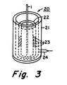
- the design of the conditioning unit also called a sweep or purge unit by virtue of its function to sweep or purge air from the surface of an incoming fiber, is illustrated in more detail in Fig. 3 of the drawing.
- the unit comprises an outer sleeve or casing 21 which acts as an enclosure for the unit to control the atmosphere therewithin, and through which the selected gas for the purge atmosphere is introduced via incoming port 24.
- inner cylindrical sleeve 22 Positioned within outer sleeve 21 is inner cylindrical sleeve 22 which is a flow director provided with gas flow channels 23 extending from the outer cylindrical surface to the inner surface thereof. These channels 23 are shown as upwardly directed channels which are effective to provide countercurrent gas flow with respect to the downward direction of fiber transport through the unit, although such flow is not always required.
- the selected flowing atmosphere for conditioning the fiber surface is introduced into the sweep unit through port 24 and is distributed about the annular chamber formed by outer sleeve 21 and inner sleeve 22 to provide uniform gas pressure in that chamber.
- This gas then flows through flow control channels 23 into the central cylindrical channel through which the optical fiber is drawn, forming a strong upward current of the selected gas through that channel and out of the unit as shown by the arrows within sleeve 22.
- An air-entraining optical fiber 1 introduced into the sweep unit from above and transported downwardly therethrough as shown is efficiently swept with the gases flowing upwardly through channels 23. This flow removes any debris present on the fiber and effectively displaces air adjacent the fiber surface before the fiber exits the sweep unit and enters the upper surface of the coating liquid.
- the following Table reports the results of a number of such fiber draws, using nitrogen and other gases and gas mixtures as purge gases. Included in the Table for each of a number of sample optical fibers are the draw speed at which the fiber was transported through the conditioner-coater apparatus, in meters per second, the composition and flow rate of the selected conditioning gas into the sweep unit, in liters per minute, and the identification of optional additive fiber conditioning vapors present in the conditioning gas, if any. Also reported are the bubble count observed in the applied coating, expressed as the number of bubbles observed by microscopic examination of a 100 ⁇ m length of fiber, and the attenuation of the coated fiber at 1300 nm wavelength, in decibels per kilometer.
- the additives present in the purge gas during some of the reported draws were introduced by bubbling the purge gas through solutions of the silanes in an acetone solvent prior to transport to the coating unit.
- the identity of the silane and concentration of the acetone solution are reported in the Table. For the 100% silane examples reported, no acetone solvent was used.
- the silanes identified are commercially obtainable from Dow Corning Corporation, Midland, Mich.
- Samples 1 - 31 and 33 are comparative examples.
Landscapes
- Life Sciences & Earth Sciences (AREA)
- Chemical & Material Sciences (AREA)
- General Life Sciences & Earth Sciences (AREA)
- Engineering & Computer Science (AREA)
- Chemical Kinetics & Catalysis (AREA)
- General Chemical & Material Sciences (AREA)
- Geochemistry & Mineralogy (AREA)
- Materials Engineering (AREA)
- Organic Chemistry (AREA)
- Optical Fibers, Optical Fiber Cores, And Optical Fiber Bundles (AREA)
- Surface Treatment Of Glass Fibres Or Filaments (AREA)
Claims (2)
- Beschichtungsvorrichtung zum Aufbringen eines schützenden organischen Beschichtungsmaterials auf eine optische Glasfaser, mit einer auf dem Transportweg der Faser durch die Vorrichtung vorgesehenen Beschichtungsform zum Aufbringen des organischen Beschichtungsmaterials als gleichförmige flüssige Schicht auf die Oberfläche der Faser, wobei die Beschichtungsform einen Fasereinlaß und ein Beschichtungsflüssigkeitsreservoir besitzt, welches einen nachfüllbaren Vorrat an Beschichtungsflüssigkeit enthält, und wobei die Beschichtungsflüssigkeit eine Eintrittsoberfläche vorsieht, durch welche die in die Form eintretende optische Faser zum Eintauchen in dieselbe transportiert wird, wobei die Form weiterhin eine stromabwärts des Beschichtungsflüssigkeitsreservoirs in Richtung des Fasertransports durch die Form angeordnete Austrittsöffnung zum Entfernen von überschüssigem Beschichtungsmaterial von der Faser vor dem Austreten der Faser aus der Form aufweist,
dadurch gekennzeichnet, daß die Vorrichtung weiterhin eine Faserkonditioniereinrichtung aufweist, die stromaufwärts der Beschichtungsform und mit deren Fasereinlaß verbunden und neben der Eintrittsoberfläche des Beschichtungmaterials angeordnet ist, wobei durch die Einrichtung die Oberfläche der Faser vor dem Transport in die Beschichtungsflüssigkeit mit einer strömenden Gasatmosphäre behandelbar ist, durch welche Luft von der Oberfläche der Faser entfernbar ist, und welche ausreichend in dem flüssigen organischen Beschichtungsmaterial zum Verringern des Eindringens von Gasblasen in dem auf die Faseroberfläche aufgebrachten Beschichtungsmaterial lösbar ist, und daß die Faserkonditioniereinrichtung eine ringförmige Verteilerkammer aufweist, die sich um den Fasertransportweg herum durch die Vorrichtung erstreckt und wenigstens eine Einlaßöffnung und zahlreiche Strömungsrichtaustrittsauslässe für das strömende Gas vorsieht, wobei die Austrittsöffnung um den Umfang der Verteilerkammer verteilt und für das Richten der Austrittströmung des strömenden Gases gegen die Oberfläche einer durch die Vorrichtung transportierten optischen Faser vorgesehen sind. - Verfahren zum Aufbringen einer schützenden organischen Beschichtung auf eine optische Glasfaser, bei dem die Glasfaser nach dem Ziehen von einer Glasvorform durch eine Flüssigkeitsbeschichtungsform transportiert wird, welche einen Fasereinlaß, einen Faserauslaß und ein Flüssigkeitsreservoir aufweist, welches eine organische Beschichtungsflüssigkeit enthält, wobei die Flüssigkeitsbeschichtungsform eine Flüssigkeitsbeschichtung auf der Faser vorsieht, wobei die Flüssigkeitsbeschichtung danach getrocknet wird, um die schützende organische Beschichtung vorzusehen, und wobei Blaseneinschlüsse in der Beschichtung durch Verringerung von Lufteinschlüssen in der Beschichtungsflüssigkeit seitens der Faser verringert werden,
dadurch gekennzeichnet, daß zu dem Verfahrensschritt des Verringerns von Lufteinschluß in der Beschichtungsflüssigkeit der Verfahrensschritt des Konditionierens der Oberfläche der Faser durch Hindurchleiten der Faser durch eine Konditionierkammer gehört, die neben dem Fasereinlaß angeordnet und bei diesem mit dem Flüssigkeitsreservoir verbunden ist, wobei die Kammer einen zylindrischen Kanal besitzt, durch den die Faser nach unten in das Reservoir gezogen wird und in dem das Konditionieren der Faseroberfläche durch Reinigen der Faseroberfläche mit einer strömenden aus im wesentlichen CO2 bestehenden Atmosphäre durchgeführt wird.
Priority Applications (1)
| Application Number | Priority Date | Filing Date | Title |
|---|---|---|---|
| AT87306483T ATE70035T1 (de) | 1986-09-25 | 1987-07-22 | Verfahren und vorrichtung zur beschichtung einer optischen wellenleiterfaser. |
Applications Claiming Priority (2)
| Application Number | Priority Date | Filing Date | Title |
|---|---|---|---|
| US06/911,479 US4792347A (en) | 1986-09-25 | 1986-09-25 | Method for coating optical waveguide fiber |
| US911479 | 1986-09-25 |
Publications (3)
| Publication Number | Publication Date |
|---|---|
| EP0261772A1 EP0261772A1 (de) | 1988-03-30 |
| EP0261772B1 EP0261772B1 (de) | 1991-12-04 |
| EP0261772B2 true EP0261772B2 (de) | 1999-08-11 |
Family
ID=25430307
Family Applications (1)
| Application Number | Title | Priority Date | Filing Date |
|---|---|---|---|
| EP87306483A Expired - Lifetime EP0261772B2 (de) | 1986-09-25 | 1987-07-22 | Verfahren und Vorrichtung zur Beschichtung einer optischen Wellenleiterfaser |
Country Status (9)
| Country | Link |
|---|---|
| US (1) | US4792347A (de) |
| EP (1) | EP0261772B2 (de) |
| JP (1) | JP2635977B2 (de) |
| KR (1) | KR950014696B1 (de) |
| AT (1) | ATE70035T1 (de) |
| AU (1) | AU591807B2 (de) |
| CA (1) | CA1256756A (de) |
| DE (1) | DE3774986D1 (de) |
| ES (1) | ES2029479T5 (de) |
Families Citing this family (30)
| Publication number | Priority date | Publication date | Assignee | Title |
|---|---|---|---|---|
| US5593736A (en) * | 1988-05-26 | 1997-01-14 | The United States Of America As Represented By The Secretary Of The Navy | Process for manufacturing a fiber reinforced optic microcable with a UV cured resin |
| JPH0620745B2 (ja) * | 1990-02-28 | 1994-03-23 | 株式会社タクマ | ワニス含浸方法及びその装置 |
| US5366527A (en) * | 1993-04-05 | 1994-11-22 | Corning Incorporated | Method and apparatus for coating optical waveguide fibers |
| US5492281A (en) * | 1993-10-04 | 1996-02-20 | Corning Incorporated | Base layer of coated glass fiber for a bobbin |
| CA2168830A1 (en) * | 1995-03-23 | 1996-09-24 | John Steele Abbott Iii | Method and apparatus for coating fibers |
| US5838866A (en) | 1995-11-03 | 1998-11-17 | Corning Incorporated | Optical fiber resistant to hydrogen-induced attenuation |
| US5922403A (en) * | 1996-03-12 | 1999-07-13 | Tecle; Berhan | Method for isolating ultrafine and fine particles |
| CA2202009A1 (en) * | 1996-04-23 | 1997-10-23 | Chester Hann-Hwei Chang | Apparatus and method for forming optical fiber coating |
| US5843231A (en) * | 1996-09-24 | 1998-12-01 | Alcatel Telecommunications Cable | Apparatus for bubble stripping and coating a fiber |
| US5997942A (en) * | 1997-04-21 | 1999-12-07 | Corning Incorporated | Apparatus and method for forming optical fiber coating |
| NL1009503C2 (nl) * | 1998-06-26 | 2000-01-04 | Plasma Optical Fibre Bv | Werkwijze voor het aanbrengen van een beschermende organische deklaag op een optische vezel van glas. |
| US6083565A (en) * | 1998-11-06 | 2000-07-04 | North Carolina State University | Method for meniscus coating with liquid carbon dioxide |
| KR100318927B1 (ko) * | 2000-01-06 | 2001-12-29 | 윤종용 | 냉각기를 구비한 광섬유 코팅 장치 |
| JP4824255B2 (ja) | 2000-07-11 | 2011-11-30 | コーニング インコーポレイテッド | 可変張力ファイバ巻取 |
| US6577802B1 (en) | 2000-07-13 | 2003-06-10 | Corning Incorporated | Application of silane-enhanced adhesion promoters for optical fibers and fiber ribbons |
| US6546758B1 (en) | 2000-08-16 | 2003-04-15 | Alcatel | Multi-chamber fiber cooling apparatus |
| US6621970B2 (en) | 2001-03-28 | 2003-09-16 | Alcatel | UV-curable optical fiber coating composition including fullerenes |
| US6892012B2 (en) * | 2001-05-18 | 2005-05-10 | Fujikura, Ltd. | Optical fiber bundle unit for transmitting ultraviolet light |
| EP1417244B1 (de) | 2001-08-17 | 2007-05-23 | Draka Comteq B.V. | Eintopfoligomersystem enthaltende strahlungshärtbare beschichtungszusammensetzung für glasfasern |
| US20040194513A1 (en) * | 2003-04-04 | 2004-10-07 | Giacobbe Frederick W | Fiber coolant system including improved gas seals |
| KR100800758B1 (ko) * | 2004-09-15 | 2008-02-01 | 엘에스전선 주식회사 | 광섬유 코팅층에 기포의 발생을 방지하기 위한 광섬유코팅장치 및 이를 이용한 코팅방법 |
| KR100594657B1 (ko) * | 2004-11-22 | 2006-07-03 | 엘에스전선 주식회사 | 고속으로 광섬유를 코팅하기 위한 광섬유 코팅장치 및 방법 |
| US7317855B2 (en) * | 2004-12-16 | 2008-01-08 | Corning Incorporated | Method of imparting twist to optical fiber |
| US20070063369A1 (en) * | 2005-09-19 | 2007-03-22 | Bridgestone Firestone North American Tire, Llc | Method of molding a tire |
| WO2010070931A1 (ja) | 2008-12-19 | 2010-06-24 | 株式会社フジクラ | 光ファイバ母材の製造方法 |
| WO2010119696A1 (ja) * | 2009-04-16 | 2010-10-21 | 株式会社フジクラ | 光ファイバ素線の製造方法 |
| CN106019506A (zh) * | 2016-07-08 | 2016-10-12 | 天津市立孚光电线缆开发有限公司 | 一种紧套光纤加工装置 |
| EP3395775B1 (de) | 2017-04-24 | 2019-06-12 | Corning Incorporated | Verfahren zum aufbringen einer beschichtungsflüssigkeit auf eine glasfaser |
| US11518709B2 (en) | 2018-04-20 | 2022-12-06 | Corning Incorporated | Optical fiber coating die assembly having inlet tube |
| CN109437600B (zh) * | 2018-11-16 | 2023-11-21 | 法尔胜泓昇集团有限公司 | 一种方便拆卸的高效光纤涂覆除气泡装置 |
Family Cites Families (19)
| Publication number | Priority date | Publication date | Assignee | Title |
|---|---|---|---|---|
| GB1507144A (en) * | 1974-07-10 | 1978-04-12 | Post Office | Apparatus for drawing dielectric optical waveguides |
| JPS54131042A (en) * | 1978-04-03 | 1979-10-11 | Nippon Telegr & Teleph Corp <Ntt> | Unit for taking up optical fiber |
| GB2105618B (en) * | 1981-09-15 | 1984-08-22 | Standard Telephones Cables Ltd | Plastics coating optical fibre |
| US4514205A (en) * | 1981-11-05 | 1985-04-30 | Corning Glass Works | Fiber cooling apparatus |
| JPS5890601A (ja) * | 1981-11-25 | 1983-05-30 | Furukawa Electric Co Ltd:The | イメ−ジフアイバの製造方法 |
| US4396409A (en) * | 1981-12-11 | 1983-08-02 | Corning Glass Works | Method of improving fatigue resistance of optical fibers |
| US4409263A (en) * | 1982-01-27 | 1983-10-11 | Western Electric Co., Inc. | Methods of and apparatus for coating lightguide fiber |
| JPS58181738A (ja) * | 1982-04-16 | 1983-10-24 | Nippon Telegr & Teleph Corp <Ntt> | 低oh光フアイバ用母材の製造方法 |
| US4473599A (en) * | 1982-05-27 | 1984-09-25 | Aetna Telecommunications Laboratories | Process for providing optical fibers conditioned for hostile environments and fibers thus formed |
| NL8203843A (nl) * | 1982-10-04 | 1984-05-01 | Philips Nv | Werkwijze en inrichting voor het trekken van een optische vezel uit een vaste voorvorm die in hoofdzaak uit sio2 en gedoteerd sio2 bestaat. |
| US4613521A (en) * | 1983-06-30 | 1986-09-23 | At&T Technologies, Inc. | Methods of and apparatus for coating a lightguide fiber |
| GB2156336A (en) * | 1984-03-27 | 1985-10-09 | Standard Telphones And Cables | Method of coating infrared optical fibres |
| GB2159812B (en) * | 1984-06-01 | 1988-02-10 | Stc Plc | Manufacturing optical fibre |
| JPS6120496A (ja) * | 1984-07-09 | 1986-01-29 | Sony Corp | 電気機械変換装置用コイル |
| US4600442A (en) * | 1984-08-14 | 1986-07-15 | Hughes Aircraft Company | Process for the removal of impurities from optical component materials |
| US4531959A (en) * | 1984-10-04 | 1985-07-30 | Corning Glass Works | Method and apparatus for coating optical fibers |
| JPS61174133A (ja) * | 1985-01-25 | 1986-08-05 | Hitachi Cable Ltd | 光フアイバの製造方法 |
| US4664689A (en) * | 1986-02-27 | 1987-05-12 | Union Carbide Corporation | Method and apparatus for rapidly cooling optical fiber |
| DD247442A1 (de) * | 1986-04-01 | 1987-07-08 | Oberspree Kabelwerke Veb K | Vorrichtung zum beschichten von lichtwellenleitern |
-
1986
- 1986-09-25 US US06/911,479 patent/US4792347A/en not_active Expired - Lifetime
-
1987
- 1987-07-07 CA CA000541416A patent/CA1256756A/en not_active Expired
- 1987-07-22 ES ES87306483T patent/ES2029479T5/es not_active Expired - Lifetime
- 1987-07-22 AT AT87306483T patent/ATE70035T1/de not_active IP Right Cessation
- 1987-07-22 DE DE8787306483T patent/DE3774986D1/de not_active Expired - Lifetime
- 1987-07-22 EP EP87306483A patent/EP0261772B2/de not_active Expired - Lifetime
- 1987-09-17 AU AU78620/87A patent/AU591807B2/en not_active Expired
- 1987-09-25 JP JP62239121A patent/JP2635977B2/ja not_active Expired - Lifetime
- 1987-09-25 KR KR1019870010618A patent/KR950014696B1/ko not_active Expired - Lifetime
Also Published As
| Publication number | Publication date |
|---|---|
| EP0261772B1 (de) | 1991-12-04 |
| AU591807B2 (en) | 1989-12-14 |
| KR890004999A (ko) | 1989-05-11 |
| ES2029479T3 (es) | 1992-08-16 |
| US4792347A (en) | 1988-12-20 |
| DE3774986D1 (de) | 1992-01-16 |
| JP2635977B2 (ja) | 1997-07-30 |
| JPS63100036A (ja) | 1988-05-02 |
| ATE70035T1 (de) | 1991-12-15 |
| AU7862087A (en) | 1988-03-31 |
| ES2029479T5 (es) | 1999-11-01 |
| EP0261772A1 (de) | 1988-03-30 |
| KR950014696B1 (ko) | 1995-12-13 |
| CA1256756A (en) | 1989-07-04 |
Similar Documents
| Publication | Publication Date | Title |
|---|---|---|
| EP0261772B2 (de) | Verfahren und Vorrichtung zur Beschichtung einer optischen Wellenleiterfaser | |
| US5974837A (en) | Method for coating fibers | |
| CA1324258C (en) | Methods of and apparatus for coating optical fiber and products produced thereby | |
| US4913859A (en) | Methods of curing optical fiber coatings | |
| EP0567961B2 (de) | Verfahren und Vorrichtung zum Ziehen von optischen Fasern | |
| US4409263A (en) | Methods of and apparatus for coating lightguide fiber | |
| US5092264A (en) | Apparatus for curing optical fiber coatings | |
| US4594088A (en) | Method and apparatus for making, coating and cooling lightguide fiber | |
| US4439467A (en) | Methods of coating lightguide fiber and product produced thereby | |
| US8374473B2 (en) | Tight-buffered optical fiber having improved fiber access | |
| KR100203544B1 (ko) | 피복 광 섬유 및 그 피복 방법 | |
| EP0314174A1 (de) | Verfahren und Vorrichtung zum Aushärten von Beschichtungen von optischen Fasern | |
| US4853258A (en) | Method for the impervious metallic coating of an optic fiber and device | |
| US5186781A (en) | Application of adhesive during optical fiber canister winding | |
| WO1983002268A1 (en) | A device in equipment for drawing glass fibres | |
| US6304704B1 (en) | Mode mixing buffered optical fiber apparatus and method for making | |
| US5242477A (en) | Apparatus for coating optical fibers | |
| US4522148A (en) | Apparatus for coating lightguide fiber | |
| AU741579B2 (en) | Method and apparatus for coating fibers | |
| EP0636590A1 (de) | Verfahren zur Verbesserung der Ausziehkraft von Polymer beschichteten optischen Fasern | |
| EP0424012B1 (de) | Verfahren zur und Vorrichtung für die Beschichtung von optischen Fasern | |
| EP0597627A1 (de) | Optisches Übertragungsmedium mit verbesserten Zugverhalten | |
| CN1631825A (zh) | 一种具有氢不敏感性光纤的制造方法 | |
| HK1000532B (en) | Method and apparatus for drawing optical fibers |
Legal Events
| Date | Code | Title | Description |
|---|---|---|---|
| PUAI | Public reference made under article 153(3) epc to a published international application that has entered the european phase |
Free format text: ORIGINAL CODE: 0009012 |
|
| AK | Designated contracting states |
Kind code of ref document: A1 Designated state(s): AT BE CH DE ES FR GB IT LI NL SE |
|
| 17P | Request for examination filed |
Effective date: 19881103 |
|
| 17Q | First examination report despatched |
Effective date: 19900615 |
|
| GRAA | (expected) grant |
Free format text: ORIGINAL CODE: 0009210 |
|
| AK | Designated contracting states |
Kind code of ref document: B1 Designated state(s): AT BE CH DE ES FR GB IT LI NL SE |
|
| REF | Corresponds to: |
Ref document number: 70035 Country of ref document: AT Date of ref document: 19911215 Kind code of ref document: T |
|
| REF | Corresponds to: |
Ref document number: 3774986 Country of ref document: DE Date of ref document: 19920116 |
|
| ITF | It: translation for a ep patent filed | ||
| ET | Fr: translation filed | ||
| REG | Reference to a national code |
Ref country code: ES Ref legal event code: FG2A Ref document number: 2029479 Country of ref document: ES Kind code of ref document: T3 |
|
| PLBI | Opposition filed |
Free format text: ORIGINAL CODE: 0009260 |
|
| 26 | Opposition filed |
Opponent name: AEG KABEL AKTIENGESELLSCHAFT Effective date: 19920901 |
|
| NLR1 | Nl: opposition has been filed with the epo |
Opponent name: AEG KABEL AG |
|
| PLAB | Opposition data, opponent's data or that of the opponent's representative modified |
Free format text: ORIGINAL CODE: 0009299OPPO |
|
| R26 | Opposition filed (corrected) |
Opponent name: AEG KABEL AKTIENGESELLSCHAFT Effective date: 19920901 |
|
| EAL | Se: european patent in force in sweden |
Ref document number: 87306483.6 |
|
| PLAB | Opposition data, opponent's data or that of the opponent's representative modified |
Free format text: ORIGINAL CODE: 0009299OPPO |
|
| R26 | Opposition filed (corrected) |
Opponent name: KABEL RHEYDT AKTIENGESELLSCHAFT Effective date: 19920901 |
|
| NLR1 | Nl: opposition has been filed with the epo |
Opponent name: KABEL RHEYDT AKTIENGESELLSCHAFT |
|
| APAC | Appeal dossier modified |
Free format text: ORIGINAL CODE: EPIDOS NOAPO |
|
| APAC | Appeal dossier modified |
Free format text: ORIGINAL CODE: EPIDOS NOAPO |
|
| APAE | Appeal reference modified |
Free format text: ORIGINAL CODE: EPIDOS REFNO |
|
| APAC | Appeal dossier modified |
Free format text: ORIGINAL CODE: EPIDOS NOAPO |
|
| RAP2 | Party data changed (patent owner data changed or rights of a patent transferred) |
Owner name: CORNING INCORPORATED |
|
| PLAW | Interlocutory decision in opposition |
Free format text: ORIGINAL CODE: EPIDOS IDOP |
|
| NLT2 | Nl: modifications (of names), taken from the european patent patent bulletin |
Owner name: CORNING INCORPORATED |
|
| PLAW | Interlocutory decision in opposition |
Free format text: ORIGINAL CODE: EPIDOS IDOP |
|
| PUAH | Patent maintained in amended form |
Free format text: ORIGINAL CODE: 0009272 |
|
| STAA | Information on the status of an ep patent application or granted ep patent |
Free format text: STATUS: PATENT MAINTAINED AS AMENDED |
|
| 27A | Patent maintained in amended form |
Effective date: 19990811 |
|
| AK | Designated contracting states |
Kind code of ref document: B2 Designated state(s): AT BE CH DE ES FR GB IT LI NL SE |
|
| REG | Reference to a national code |
Ref country code: CH Ref legal event code: AEN Free format text: MAINTIEN DU BREVET DONT L'ETENDUE A ETE MODIFIEE |
|
| ITF | It: translation for a ep patent filed | ||
| PGFP | Annual fee paid to national office [announced via postgrant information from national office to epo] |
Ref country code: CH Payment date: 19991007 Year of fee payment: 13 |
|
| ET3 | Fr: translation filed ** decision concerning opposition | ||
| REG | Reference to a national code |
Ref country code: ES Ref legal event code: DC2A Kind code of ref document: T5 Effective date: 19990921 |
|
| NLR3 | Nl: receipt of modified translations in the netherlands language after an opposition procedure | ||
| PGFP | Annual fee paid to national office [announced via postgrant information from national office to epo] |
Ref country code: ES Payment date: 20000712 Year of fee payment: 14 |
|
| PG25 | Lapsed in a contracting state [announced via postgrant information from national office to epo] |
Ref country code: LI Free format text: LAPSE BECAUSE OF FAILURE TO SUBMIT A TRANSLATION OF THE DESCRIPTION OR TO PAY THE FEE WITHIN THE PRESCRIBED TIME-LIMIT Effective date: 20000731 Ref country code: CH Free format text: LAPSE BECAUSE OF FAILURE TO SUBMIT A TRANSLATION OF THE DESCRIPTION OR TO PAY THE FEE WITHIN THE PRESCRIBED TIME-LIMIT Effective date: 20000731 |
|
| REG | Reference to a national code |
Ref country code: CH Ref legal event code: PL |
|
| PGFP | Annual fee paid to national office [announced via postgrant information from national office to epo] |
Ref country code: BE Payment date: 20010814 Year of fee payment: 15 |
|
| REG | Reference to a national code |
Ref country code: GB Ref legal event code: IF02 |
|
| PGFP | Annual fee paid to national office [announced via postgrant information from national office to epo] |
Ref country code: AT Payment date: 20020613 Year of fee payment: 16 |
|
| PGFP | Annual fee paid to national office [announced via postgrant information from national office to epo] |
Ref country code: SE Payment date: 20020703 Year of fee payment: 16 |
|
| PG25 | Lapsed in a contracting state [announced via postgrant information from national office to epo] |
Ref country code: ES Free format text: LAPSE BECAUSE OF NON-PAYMENT OF DUE FEES Effective date: 20020723 |
|
| PG25 | Lapsed in a contracting state [announced via postgrant information from national office to epo] |
Ref country code: BE Free format text: LAPSE BECAUSE OF NON-PAYMENT OF DUE FEES Effective date: 20020731 |
|
| BERE | Be: lapsed |
Owner name: *CORNING INC. Effective date: 20020731 |
|
| PG25 | Lapsed in a contracting state [announced via postgrant information from national office to epo] |
Ref country code: AT Free format text: LAPSE BECAUSE OF NON-PAYMENT OF DUE FEES Effective date: 20030722 |
|
| PG25 | Lapsed in a contracting state [announced via postgrant information from national office to epo] |
Ref country code: SE Free format text: LAPSE BECAUSE OF NON-PAYMENT OF DUE FEES Effective date: 20030723 |
|
| EUG | Se: european patent has lapsed | ||
| REG | Reference to a national code |
Ref country code: ES Ref legal event code: FD2A Effective date: 20030811 |
|
| APAH | Appeal reference modified |
Free format text: ORIGINAL CODE: EPIDOSCREFNO |
|
| PGFP | Annual fee paid to national office [announced via postgrant information from national office to epo] |
Ref country code: FR Payment date: 20060717 Year of fee payment: 20 |
|
| PGFP | Annual fee paid to national office [announced via postgrant information from national office to epo] |
Ref country code: NL Payment date: 20060724 Year of fee payment: 20 |
|
| PGFP | Annual fee paid to national office [announced via postgrant information from national office to epo] |
Ref country code: GB Payment date: 20060726 Year of fee payment: 20 |
|
| PGFP | Annual fee paid to national office [announced via postgrant information from national office to epo] |
Ref country code: IT Payment date: 20060731 Year of fee payment: 20 |
|
| PGFP | Annual fee paid to national office [announced via postgrant information from national office to epo] |
Ref country code: DE Payment date: 20060831 Year of fee payment: 20 |
|
| PG25 | Lapsed in a contracting state [announced via postgrant information from national office to epo] |
Ref country code: NL Free format text: LAPSE BECAUSE OF EXPIRATION OF PROTECTION Effective date: 20070722 |
|
| REG | Reference to a national code |
Ref country code: GB Ref legal event code: PE20 |
|
| NLV7 | Nl: ceased due to reaching the maximum lifetime of a patent |
Effective date: 20070722 |
|
| PG25 | Lapsed in a contracting state [announced via postgrant information from national office to epo] |
Ref country code: GB Free format text: LAPSE BECAUSE OF EXPIRATION OF PROTECTION Effective date: 20070721 |