EP0261682A2 - Hydraulische Pumpen oder Motoren und hydrostatische Getriebeanlagen - Google Patents
Hydraulische Pumpen oder Motoren und hydrostatische Getriebeanlagen Download PDFInfo
- Publication number
- EP0261682A2 EP0261682A2 EP87113990A EP87113990A EP0261682A2 EP 0261682 A2 EP0261682 A2 EP 0261682A2 EP 87113990 A EP87113990 A EP 87113990A EP 87113990 A EP87113990 A EP 87113990A EP 0261682 A2 EP0261682 A2 EP 0261682A2
- Authority
- EP
- European Patent Office
- Prior art keywords
- pump
- motor
- effect
- capacity
- brake
- Prior art date
- Legal status (The legal status is an assumption and is not a legal conclusion. Google has not performed a legal analysis and makes no representation as to the accuracy of the status listed.)
- Granted
Links
Images


Classifications
-
- F—MECHANICAL ENGINEERING; LIGHTING; HEATING; WEAPONS; BLASTING
- F04—POSITIVE - DISPLACEMENT MACHINES FOR LIQUIDS; PUMPS FOR LIQUIDS OR ELASTIC FLUIDS
- F04C—ROTARY-PISTON, OR OSCILLATING-PISTON, POSITIVE-DISPLACEMENT MACHINES FOR LIQUIDS; ROTARY-PISTON, OR OSCILLATING-PISTON, POSITIVE-DISPLACEMENT PUMPS
- F04C14/00—Control of, monitoring of, or safety arrangements for, machines, pumps or pumping installations
- F04C14/18—Control of, monitoring of, or safety arrangements for, machines, pumps or pumping installations characterised by varying the volume of the working chamber
- F04C14/185—Control of, monitoring of, or safety arrangements for, machines, pumps or pumping installations characterised by varying the volume of the working chamber by varying the useful pumping length of the cooperating members in the axial direction
-
- F—MECHANICAL ENGINEERING; LIGHTING; HEATING; WEAPONS; BLASTING
- F16—ENGINEERING ELEMENTS AND UNITS; GENERAL MEASURES FOR PRODUCING AND MAINTAINING EFFECTIVE FUNCTIONING OF MACHINES OR INSTALLATIONS; THERMAL INSULATION IN GENERAL
- F16H—GEARING
- F16H39/00—Rotary fluid gearing using pumps and motors of the volumetric type, i.e. passing a predetermined volume of fluid per revolution
- F16H39/04—Rotary fluid gearing using pumps and motors of the volumetric type, i.e. passing a predetermined volume of fluid per revolution with liquid motor and pump combined in one unit
- F16H39/06—Rotary fluid gearing using pumps and motors of the volumetric type, i.e. passing a predetermined volume of fluid per revolution with liquid motor and pump combined in one unit pump and motor being of the same type
Definitions
- the present invention relates to the field of hydraulic transmitting technique, especially relates to hydraulic pumps or motors and hydrostatic transmitting systems.
- the current variable capacity pumps (or motors, similarly hereinafter) only have two types, namely the reciprocal plunger type and single action rotary vane type of variable capacity pumps.
- the plunger type variable capacity pumps are extremely sensitive to dust in the oil, and their costs are very high.
- the performance parameters of single action vane type variable capacity pumps are very poor.
- the pum or motor effect resulting from current hydraulic pumps or motors themselves is not changeable. In order to realize some specific functions in practical applications, some additional hydraulic elements are therefore needed for regulation purpose, thus leading to a giant system with complicated components and high costs. Consequently, the application field of hydrostatic transmitting systems is limited.
- hydro-mechanical transmitting systems are still used in current vehicles, although they have three disadvantages: first, the transmitting efficiency is low; secondly, the structure is complicated and the cost is high; thirdly, power cannot be transmitted inversely.
- the fundamental cause leading to these disadvantages lies in the vortex type hydraulic torque converter (composed of an impeller, a guide torus and a turbine) used in the system. This torque converter operates with high efficiency only in a very narrow range of speed ratio, beyond which the transmitting efficiency will decrease rapidly, and the torque converter cannot transmit power inversely either.
- the purpose of the present invention is to provide an axial variable capacity pump or motor, especially an axial variable capacity gear pump or motor and an axial variable capacity double action vane pump or motor with simple structure, low cost, good adaptability and wide variable range, so as to overcome the aforementioned disadvantages existing in prior arts.
- Another purpose of the present invention is to provide a simple structured effect-changeable pump or motor in which the pump or motor effect can be changed.
- Still another purpose of the present invention is to provide a basic hydrostatic transmitting system which employs the hydraulic pump or motor of the present invention.
- Another purpose of the present invention is to provide a hydrostatic transmitting system which employs the hydraulic pump or motor of the present invention and is especially suitable to vehicles.
- the capacity of the hydraulic pump will proportionally varied.
- a sliding means which can rotate together with the rotary part of the pump and is slidable axially with respect to the rotary part. When it slides towards one side to shorten the working chamber length, the working volume will be reduced. Sliding towards another side will increase the working volume. The axial movement of the sliding means will therefore change the delivery capacity of pump.
- the sliding means is termed as "capacity change member" in the present invention.
- an "axial variable capacity pump” is thus formed.
- a basic hydrostatic transmitting system or termed as "axial variable capacity torque converter" of the present invention is then formed.
- the present invention also provides a function or effect-changeable pump or motor.
- any kind of rotary hydraulic pumps possesses a rotating component and a sealing component contacting the former. When these two components closely contact each other, a pump effect will be produced; when they are separated from each other, the pump effect will vanish.
- the sealing component in the present invention is movable relative to the rotating component. When it moves forwards, it will contact the rotating component, and when it moves backwards it will separate itself from the rotating component, thereby to control the producing, vanishing strengthening and weakening of the pump effect.
- this movable sealing component is termed as "effect change member”
- the pump or motor which has the effect change member is termed as "effect-changeable pump” or "effect-changeable motor”.
- effect change member the pump or motor which has the effect change member
- effect-changeable pump or "effect-changeable motor”.
- the basic hydrostatic transmitting system of the present invention which includes the effect-changeable pump or motor and the axial variable capacity pump or motor has much better performance than ordinary hydrostatic transmitting systems.
- Input shaft 1 rotates together with driving gear 3 which drives the mating gear 11, the rotating direction being shown in Fig. 1 (c).
- driving gear 3 which drives the mating gear 11, the rotating direction being shown in Fig. 1 (c).
- radial seal blocks 7 and 12 fixed end plate 8 (assembled together with the casing), sliding end plate 5 and capacity change members 10 and 4, the oil is pumped from low pressure area 1 to high pressure area h, by flowing into the casing through a wide inlet opening 9 and flowing out of the casing through a wide outlet opening 23.
- the capacity change member 10 is an internal ring gear sleeved onto gear 11 and rotatable with gear 11.
- a ring gear-shaped elastic gasket 24 which functions as the radial seal in the tooth clearance (see also enlarged views Fig.
- Fig. 1 (e) The capacity change member is rigidly contacted with the gear along most axial length in order to provide a good positioning and supporting. It may be seen from enlarged view Fig. 1 (d) that capacity change member 10 has a flange which is used to withstand oil pressure and functions as a seal. Capacity change member 4 has the same structure, which is sleeved onto gear 3 and rotatable in sliding end plate 5. In Fig. 1 (a), reference numbers 2, 14 and 15 indicate needle bearings. Sliding end plate 5 may axially slide together with gear 11 and radial seal block 7, and forms the axial sealing on the right side together with coapcity change member 4, radial seal blocks 7 and 12 and gaskets 6 and 13.
- Radial seal blocks 7 and 12 have slots alternating with flanges on their outer surface, which fit with the slots and flanges on the inner circumference of the casing in order to prevent radial seal blocks from sliding twoards low pressure area under the load of oil pressure in high pressure area. Some slots connecting the high pressure area are formed also on the outer surface of radial seal blocks in order to introduce some pressurized oil into these slots to balance the radial pressure of the high pressurize oil in tooth clearance, thus making the sliding end plate easier to move. Under the action of the pressurized oil and the elasticity of gaskets 6 and 13, the radial clearance between radial seal blocks and gears is compensated (the aforementioned slots and flanges are not shown in Fig. 1). The clearances between radial seal blocks and fixed or sliding end plate are also sealed by gaskets.
- partition plate 8 integrated with the casing is provided to separate the higher and lower pressure area.
- the compensation of axial clearance between gears and end plates can easily be realized using well known technique. It is worth special notice that when the pump in Fig. 1 (a) is used as a torque converter for vehicles, its input shaft should be connected with transmitting shaft 21. Making use of the splined sleeve which can move forward and backward along the transmitting shaft and inserting a small spring 22, the axial clearance of gear 3 may be compensated.
- a piston 19 to which control rod 18 is connected.
- the other end of the control rod is fixed onto the pressure center of sliding end plate.
- a hole 20 is drilled on cylinder 16 in order to lead high pressurized oil into the cylinder to form a pressure on piston 19.
- the area of the piston is so designed as to use most of the pressure to balance the high pressure acting on the left side of sliding end plate, and use small part of the pressure to compress spring 17.
- Fig. 2 an embodiment of axial variable capacity internal gear pumps is shown in Fig. 2.
- the operation principle of internal gear pumps is well known. Referring to sketch 2 (b), gear 5d internally meshes with ring gear 6d. When the pump is rotating in the direction as shown in the figure under the sealing action of radial seal block 11d, the oil will be pumped from low pressure area 1 into high pressure area h. If, in Fig. 2 (a), raidla seal block 11d and gear 5d move leftward with sliding end plates 4d and 7d, the meshing length of gear 5d and internal ring gear 6d namely the working length L will then be lengthened, or shortened otherwise.
- Capacity change member 8d is an external ring gear closely sleeved into internal rign gear 6d, rotatable around left sliding end plate 7d, and movable together with 7d, thereby forming the axial sealing on left side.
- Gear 5d is supported on needle bearing 9d at the left end and rotatable in unrotatable end plate 7d. Sliding end plate 4d forms the axial sealing on right side.
- the interval denoted by length F is the area of "idle running", the cross section of which is shown in Fig. 2(c).
- gear 5d rotates within two radial seal blocks 3d and 11d, pumping oil from area 1 into area h, meanwhile pumping the same amount of oil from area h back to area 1. Therefore, no pumping effect exists within interval F, hence ensuring an effective variation of capacity when working length L is changed.
- 1d is the input shaft driving gear 5d
- 9d and 12d are needle bearings and 10d the casing.
- An axial variable capacity vane pump can also be formed according to the same principle aforementioned.
- An embodiment of axial variable capacity double action vane pumps is shown in Fig. 3.
- the operation principle of double action vane pumps is well known and can be briefly described using the sketch Fig. 3 (b) which is a cross section view within working length L.
- Fig. 3 (b) is a cross section view within working length L.
- vanes 5f and 13f radially movable outward and inward in the rotor contact with the inner surface of stator 3f and pump oil from low pressure area 1 into high pressure area h. Only one set of vanes are shown in the figure.
- capacity change member 6f located on left side is shown using a revolved sectional view.
- capacity change member 6f may rotate with rotor 10f.
- Inside capacity change member 6f is a chamber for rotor 10f and vanes 5f and 13f to slide inward and outward as shown in Fig. 3 (a).
- sealing blades 7f and 12f respectively contact with the edges of vanes 5f and 13f, thus improving the sealing among capacity change member, stator and vanes.
- Sliding end plate 4f is unrotatable, it forms the right side axial sealing in the chamber of stator 3f.
- An axial variable capacity single action vane pump may be formed with the similar structure as mentioned above. The only difference is that the capacity change member is coaxial with rotor but eccentric to stator since rotor is eccentric.
- An axial variable capacity motor can be formed using the same principle and structure aforementioned.
- the capacity change member in Fig. 3 is designed relatively larger with the consideration that it can be used as a flywheel for the engine, otherwise, it may be shortened as an end plate.
- those parts aforementioned which form the axial sealing e.g. sliding end plate, fixed end plate and capacity cnage member, etc.
- those forming the radial sealing e.g. radial seal blocks, stator, etc.
- radial seal members e.g. radial seal blocks, stator, etc.
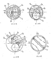
- effect-changeable gear motors An embodiment of effect-changeable gear motors is shown in Fig. 4. Meshing gears 1k and 2k are installed in casing 5k. The shadowed area denoted by 3k is the axial inlet of high pressure oil, and the area denoted by 6k is the axial outlet of the oil. Effect change member is denoted by 4k, the position of which shown in the figure is the "zero effect" position. At this position, the effect change member stands apart from the gears, oil running idly from 3k to 6k, unable to drive the gears. When effect change member 4k moves in the direction as shown by the arow to approach the gears, motor effect gradually increases.
- the axial seal plate (not shown) of the motor is floatingly assembled and may function as an axial clearance compensator. Since the effect change member is radially movable, it may also be used as a radial clearance compensator. This is an advantage over ordinary gear motor.
- Effect-changeable motor has some advantages over fluid couplings: the efficiency does not decrease with the reduction of input speed; the load variation at output end in full effect position does not lead to speed variation caused by motor; vehicle may be started at any constant engine speed (if engine torque is sufficient); stepless regulation of output power, torque and speed may be realized with little variation of efficiency; vehicle may be fully braked; power may be transmitted inversely; the power shaft and working shaft do not have to be aligned with each other.
- effect-changeable internal gear motors is shown in Fig. 5.
- Notations 1p and 2p respectively represent the internal ring gear and external gear meshing with the former.
- the shadowed areas denoted by 5p and 6p are the inlet and outlet for the oil respectively.
- the rotating directions of gears 1p and 2p are shown by arrows.
- Effect change member is denoted by 4p, which is mounted on a rotatable axle 3p.
- the position of effect change member shown in the figure is "full effect" position.
- the clockwise torque around the center of axle 3p caused by the high pressure acting on the left upper part of effect change member 4p may be slightly greater than the counterclockwise torque at the lower part so as to compensate the radial clearance. This can be done by properly designing the center position of axle 3p.
- the compensation of axial clearance is achieved by an axial floating end plate (not shown in the figure).
- the mechanism formed by using an effect-changeable pump of the present invention as a drive means of a hydraulic motor may be utilized to replace current fluid couplings. Its transmitting efficiency will be higher than that of fluid couplings at low speed, and may rotate and transmit power inversely.
- a reverse gear is needed in gear box for a vehicle to travel reversely.
- This funciton also may be realized by an effect- changeable motor.
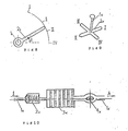
- three meshing gears 1q, 4q and 5q are mounted in case 8q (two pairs of gears may be used).
- the shadowed areas denoted by 3q and 6q are respectively the inlet and outlet for the oil. If the rotating direc- tion of gear 1q is positive when effect change member 2q is at full effect position and effect change member 7q is at zero effect position, then gear 1q will rotate in negative direction when effect change member 2q is back to zero effect position and effect change member 7q moves forward to its full effect position.
- the function of reverse gear may also be achieved by reversing the oil flow, namely by exchanging the inlet and outlet of variable capacity pump so as to make the motor rotate reversely.
- the section area of directional valve should be as large as possible.
- An example is shown in Fig. 7.
- Throttle 2r may rotate in valve housing 1r. At the position shown in the figure, oil flows into opening h and outside opening I, the returning oil then flows through openings o and l. If the throttle 2r rotates by an angle of 45°, the flow dirction will then be reversed, and the motor rotates in a reverse direction.
- two effect-changeable motors for driving two driving wheels may be integrated with axial variable capacity pump. These three can be assembled in a common casing with a common high pressure area and low pressure area in order to save some pipe and lessen pipe resistance.
- the transmitting shaft connecting to engine for driving the variable capacity pump and the output shaft of motor together form a "T" shape.
- the top dash of letter T represents the driving axle of the vehicle. In this case, two motors are connected in parallel, therefore they have the automatic differential function.
- the motor for inner side wheel When the vehicle makes a turn, the motor for inner side wheel will rotate slower since the resistant torqur is larger and the oil flowing into the motor is less, while the motor for outer side wheel will rotate faster since the resistant torque is smaller and the motor can get more oil.
- the "differential interlocking function" can be easily obtained. if the wheel at one side is trapped in the mud and can only slip, the oil pipe leading to the motor on this side is then cut-off, the motor at the unslipping side will obtain sufficient toque. If the motor shown in Fig. 6 is employed, the effect change member for reverse rotation of the motor at the slipping side (e.g. effect change member 7q) may be pushed to its full effect position, so that very great resistant torque will be produced, functioning as a differential interlocking mechanism.
- effect change member for reverse rotation of the motor at the slipping side e.g. effect change member 7q
- the operating system of the vehicle may be rearranged as follows:
- the energy When slowing down or braking the vehicle, to avoid too great temperature rise caused by the conversion from vehicle kinetic energy into heat, the energy must be led outside the system.
- the best way to solve the problem is to store this energy for future use.
- the low pressure area in axial variable capacity torque converter becomes high pressure area (since in this case, the wheels of vehicle drive effect-changeable motor to make it become a pump), which is connected to an accumulator through a check valve.
- the high pressure oil is then led to a well known type of accumulator.
- the stored energy may be utilized to start the engine, for instance, the high pressure oil may be led out to drive an axial variable capacity pump, thereby starting the engine.
- This energy may also be used as the power of direction turn booster and window wiper. If a truck with the dead weight of 4 tons and loading capacity of 2 tons travels at the spped of 36 km/h, it will possess a kinetic energy of 300, 000 joule. Assuming 70% of this energy can be stored in the accumulator when the vehicle is braked to zero speed, the stored energy is sufficient to start the engine of JIEFANG CA-10B type truck for 8 times. If it is utilized to compress the air, it may compress air for 4.7 minutes for a one horsepower compressor. This time is enough for a vehicle travelling at 36 km/h to move a distance of 2.85 kms. This is suitable to buses and trucks in cities. This advantage comes from reversibility of hidraulic motors.
- a filter may be connected in the hydrostatic transmitting system between low pressure and high pressure areas as shown in Fig. 10.
- the 1 end of thin pipes 1x is connected to low pressure area and h end to high pressure area.
- Check valve 2x opens only when the pressure in low pressure area is higher than that in high pressure area.
- the filter with high efficiency is denoted by 3x.
- Valve 4x is normally open (i.e. the position shown in the figure) and closed during emergent brake. Therefore, only when slowing down the vehicle can the oil be partly filtered, no resistance existing in the filter during normal operation. Therefore, the filter having greater resistance can be utilized without causing notable resistance in the system.
- the axial variable capacity rotary positve displacement pump presented in this invention has the advantages of simpler structure, lower cost and better ability to withstand dirty oils.
- the basic hydrostatic transmitting system i.e. axial variable capacity torque converter
- the axial variable capacity torque converter may keep its high efficiency in a almost infinite range of speed ratio (L may approach zero), while vortex type torque converter can keep its high efficiency only in a very narrow range of speed ratio.
- the average efficiency of the former is therefore higher than that of the latter in practical application.
- the axial variable capacity torque converter can reversely transmit power, can rotate inreverse direction (reverse gear), can allow input and output shafts to run idle, can stably operate at very low input speed, and can also be utilized as a brake, etc.
- the present invention has advantages over current hydro-mechanical transmission in all aspects of main performances:
- the hydrostatic transmitting system of the present invention when compared with current mechanical transmitting systems, the hydrostatic transmitting system of the present invention also has advantages:
- the hydrostatic transmitting system of the present invention has the following features when compared with current mechanical transmission:
- the hydrostatic transmitting system of the present invention is of high efficiency.
Landscapes
- Engineering & Computer Science (AREA)
- General Engineering & Computer Science (AREA)
- Mechanical Engineering (AREA)
- Rotary Pumps (AREA)
- Details And Applications Of Rotary Liquid Pumps (AREA)
- Hydraulic Motors (AREA)
- Control Of Fluid Gearings (AREA)
Applications Claiming Priority (2)
| Application Number | Priority Date | Filing Date | Title |
|---|---|---|---|
| CN86106471.2A CN1009024B (zh) | 1986-09-24 | 1986-09-24 | 轴向变量泵或马达 |
| CN86106471 | 1986-09-24 |
Publications (3)
| Publication Number | Publication Date |
|---|---|
| EP0261682A2 true EP0261682A2 (de) | 1988-03-30 |
| EP0261682A3 EP0261682A3 (en) | 1989-02-08 |
| EP0261682B1 EP0261682B1 (de) | 1991-09-04 |
Family
ID=4803229
Family Applications (1)
| Application Number | Title | Priority Date | Filing Date |
|---|---|---|---|
| EP87113990A Expired EP0261682B1 (de) | 1986-09-24 | 1987-09-24 | Hydraulische Pumpen oder Motoren und hydrostatische Getriebeanlagen |
Country Status (7)
| Country | Link |
|---|---|
| US (2) | US4872536A (de) |
| EP (1) | EP0261682B1 (de) |
| JP (1) | JPS63159688A (de) |
| CN (2) | CN1009024B (de) |
| DE (1) | DE3772688D1 (de) |
| HK (1) | HK133793A (de) |
| SG (1) | SG120693G (de) |
Cited By (7)
| Publication number | Priority date | Publication date | Assignee | Title |
|---|---|---|---|---|
| DE4303494A1 (de) * | 1993-02-06 | 1994-08-11 | Siegfried Ehlen | Verfahren zur Volumenstromregelung von Zahnradpumpen und Zahnradpumpe zur Durchführung des Verfahrens |
| RU2123602C1 (ru) * | 1997-05-30 | 1998-12-20 | Александр Николаевич Зимников | Роторная машина |
| WO2001040658A1 (en) * | 1999-11-30 | 2001-06-07 | H-Drive International Pty Ltd | Variable flow pump |
| RU2194190C2 (ru) * | 2000-08-01 | 2002-12-10 | Патрушев Геннадий Сергеевич | Шестеренный насос регулируемой реверсивной производительности |
| RU2205981C2 (ru) * | 2001-03-14 | 2003-06-10 | Шварлис Арвидас Юозович | Роторная пластинчатая машина |
| RU2208706C2 (ru) * | 2001-05-30 | 2003-07-20 | Воронежский государственный аграрный университет им. К.Д.Глинки | Регулируемая объемная гидромашина |
| WO2022028523A1 (zh) * | 2020-08-05 | 2022-02-10 | 章睿承 | 多叶型可轴向变化容积的吸排装置及其组成的变速驱动系统 |
Families Citing this family (22)
| Publication number | Priority date | Publication date | Assignee | Title |
|---|---|---|---|---|
| CN1029379C (zh) * | 1990-02-21 | 1995-07-26 | 郑悦 | 平衡式行星齿轮泵或马达 |
| US5184947A (en) * | 1991-05-21 | 1993-02-09 | Dwight Coombe | Fully variable output hydraulic gear pump having an axially translatable gear |
| US6244839B1 (en) * | 1997-11-14 | 2001-06-12 | University Of Arkansas | Pressure compensated variable displacement internal gear pumps |
| RU2177085C2 (ru) * | 1999-05-07 | 2001-12-20 | Бодогазин Сергей Борисович | Насос шестеренный регулируемый |
| US6247295B1 (en) * | 1999-10-28 | 2001-06-19 | New Holland North America, Inc. | Hydro-mechanical transmission system for an agricultural combine |
| CN100406320C (zh) * | 2002-01-14 | 2008-07-30 | 郑悦 | 车辆的制动储能驱动 |
| AT413140B (de) * | 2003-03-28 | 2005-11-15 | Tcg Unitech Ag | Zahnradpumpe |
| KR101177594B1 (ko) * | 2004-12-22 | 2012-08-27 | 마그나 파워트레인 인크. | 가변 커패시티 제로터 펌프 |
| RU2307261C1 (ru) * | 2006-02-26 | 2007-09-27 | Государственное образовательное учреждение высшего профессионального образования "Тамбовский государственный технический университет" (ГОУВПО ТГТУ) | Жидкостно-кольцевая машина |
| KR20080097240A (ko) * | 2006-02-28 | 2008-11-04 | 마그나 파워트레인 인크. | 속도 관련 제어 기구를 갖는 동적 평형기 |
| CN101713399A (zh) * | 2008-10-04 | 2010-05-26 | 郑悦 | 静液可分合变速器 |
| US8292597B2 (en) * | 2008-10-16 | 2012-10-23 | Pratt & Whitney Canada Corp. | High-speed gear pump |
| DE102009054931A1 (de) * | 2009-12-18 | 2011-06-22 | Robert Bosch GmbH, 70469 | Handgeführtes Elektrowerkzeug mit einer Drehmomentkupplung |
| MX2012011730A (es) * | 2010-04-12 | 2013-02-26 | Figura Pavol | Bomba de engranajes con un caudal de salida continuo variable. |
| DE102012210048A1 (de) * | 2012-06-14 | 2013-12-19 | Joma-Polytec Gmbh | Verdrängerpumpe |
| KR20140140011A (ko) * | 2013-05-03 | 2014-12-08 | 장순길 | 가변 용량형 기어 펌프 |
| CN105275787A (zh) * | 2014-07-16 | 2016-01-27 | 张龙 | 一种液压变量泵 |
| CN105351304A (zh) * | 2015-12-15 | 2016-02-24 | 北奔重型汽车重庆有限公司 | 宽体矿用自卸汽车大流量转向油泵主动齿轮驱动连接结构 |
| CN112833004B (zh) * | 2021-01-19 | 2024-01-12 | 南通油顺液压机械有限公司 | 一种内啮合齿轮泵 |
| CN113083391B (zh) * | 2021-04-07 | 2022-04-12 | 宁儿医院股份有限公司 | 一种新型移液枪头填装装置 |
| CN114013618B (zh) * | 2021-11-11 | 2022-10-21 | 南京航空航天大学 | 一种分布式驱动的水面船舶推进系统及其工作方法 |
| CN114103896B (zh) * | 2021-12-22 | 2023-05-26 | 北京零极创新科技有限公司 | 防抱死制动装置、车辆、电动车及电助力车辆 |
Family Cites Families (33)
| Publication number | Priority date | Publication date | Assignee | Title |
|---|---|---|---|---|
| US1742215A (en) * | 1927-03-29 | 1930-01-07 | Reginald J S Pigott | Rotary fluid unit |
| US2052419A (en) * | 1934-09-14 | 1936-08-25 | Manning Maxwell & Moore Inc | Variable delivery gear pump |
| US2258504A (en) * | 1937-06-04 | 1941-10-07 | Keelavite Co Ltd | Rotary fluid pressure engine and the like |
| US2293126A (en) * | 1939-04-24 | 1942-08-18 | Fersing Leif | Gear pump or motor |
| DE762409C (de) * | 1943-10-23 | 1955-03-17 | Graetz A G | Zahnradpumpe oder Motor |
| US2526830A (en) * | 1945-06-22 | 1950-10-24 | Hpm Dev Corp | Variable delivery gear pump |
| US2485240A (en) * | 1946-06-10 | 1949-10-18 | Carlton L Jackson | Reversible variable-speed rotary pump and motor hydraulic transmission |
| US2645903A (en) * | 1947-02-20 | 1953-07-21 | Douglas A Elkins | Variable ratio rotary pump and motor hydraulic transmission |
| US2666293A (en) * | 1949-04-21 | 1954-01-19 | Vigneau Marcel Victor | Rotary pump and motor hydraulic transmission |
| US2631695A (en) * | 1949-06-27 | 1953-03-17 | Daniel F Mcgill | Hydraulic brake and pump |
| US2684636A (en) * | 1949-12-05 | 1954-07-27 | Arthur P Heldenbrand | Variable capacity gear pump |
| US2772755A (en) * | 1950-07-13 | 1956-12-04 | Daimler Benz Ag | Pump type hydraulic brake |
| US2728299A (en) * | 1951-11-21 | 1955-12-27 | Keelavite Co Ltd | Variable capacity rotary hydraulic pump or motor |
| US3185241A (en) * | 1952-02-14 | 1965-05-25 | Case Co J I | Fluid drive tractor |
| US2989151A (en) * | 1957-02-19 | 1961-06-20 | Gassot Rene | Liquid brakes |
| US2963981A (en) * | 1957-03-11 | 1960-12-13 | Hanastsuka Tadashi | Variable discharge rotary pump |
| US2955541A (en) * | 1957-05-31 | 1960-10-11 | Engineering & Res Lab Service | Variable flow pump |
| US2979036A (en) * | 1958-05-09 | 1961-04-11 | Sven A Noren | Hydraulic rotary engine |
| FR1258654A (fr) * | 1960-06-01 | 1961-04-14 | Svenska Rotor Maskiner Ab | Détendeur à rotors hélicoïdaux, à inversion de marche |
| GB1152188A (en) * | 1966-09-15 | 1969-05-14 | Tozaburo Kuhara | A Rotary Fluid Pump or Motor |
| US3593828A (en) * | 1966-12-06 | 1971-07-20 | Teves Gmbh Alfred | Hydrodynamic brake |
| US3588295A (en) * | 1969-08-29 | 1971-06-28 | Lowell E Burk | Variable output gear pump or motor apparatus |
| US3669577A (en) * | 1970-01-02 | 1972-06-13 | Swan G Swanson | Variable high speed gear pump |
| US3805928A (en) * | 1972-08-18 | 1974-04-23 | Bennes Marrel | Regulation device for hydraulic turbo-retarders |
| FR2278991A2 (fr) * | 1974-04-29 | 1976-02-13 | Sulzer Constr Mecan | Freins rotatifs electro-hydrauliques |
| GB1539515A (en) * | 1976-02-26 | 1979-01-31 | Rolls Royce | Variable delivery gear pumps |
| FR2454561A2 (fr) * | 1979-04-20 | 1980-11-14 | Sulzer Ag | Frein rotatif electrohydraulique |
| DK160720C (da) * | 1979-10-30 | 1991-09-16 | Sulzer Constr Mecan | Roterende hydraulisk maskine |
| DE3042017A1 (de) * | 1980-11-07 | 1982-06-24 | Daimler-Benz Ag, 7000 Stuttgart | Retarder fuer fahrzeuge, mit wenigstens einem inneren hydrodynamischen arbeitskreislauf |
| US4451094A (en) * | 1981-11-05 | 1984-05-29 | Martin Jose L | Hydraulic trailer brake |
| US4497393A (en) * | 1981-12-04 | 1985-02-05 | Brems John Henry | Rotary retardation devices |
| US4551080A (en) * | 1983-10-19 | 1985-11-05 | Geiger Cletus M | Variable displacement sliding vane pump/hydraulic motor |
| DE3528651A1 (de) * | 1985-08-09 | 1987-02-19 | Rohs Hans Guenther Prof Dr Ing | Zahnradpumpe |
-
1986
- 1986-09-24 CN CN86106471.2A patent/CN1009024B/zh not_active Expired
-
1987
- 1987-09-23 US US07/100,103 patent/US4872536A/en not_active Expired - Fee Related
- 1987-09-24 DE DE8787113990T patent/DE3772688D1/de not_active Expired - Lifetime
- 1987-09-24 JP JP62237574A patent/JPS63159688A/ja active Pending
- 1987-09-24 EP EP87113990A patent/EP0261682B1/de not_active Expired
-
1989
- 1989-07-27 US US07/386,295 patent/US4932504A/en not_active Expired - Fee Related
- 1989-08-01 CN CN89105566.5A patent/CN1018278B/zh not_active Expired
-
1993
- 1993-11-02 SG SG120693A patent/SG120693G/en unknown
- 1993-12-02 HK HK1337/93A patent/HK133793A/en unknown
Non-Patent Citations (1)
| Title |
|---|
| None |
Cited By (7)
| Publication number | Priority date | Publication date | Assignee | Title |
|---|---|---|---|---|
| DE4303494A1 (de) * | 1993-02-06 | 1994-08-11 | Siegfried Ehlen | Verfahren zur Volumenstromregelung von Zahnradpumpen und Zahnradpumpe zur Durchführung des Verfahrens |
| RU2123602C1 (ru) * | 1997-05-30 | 1998-12-20 | Александр Николаевич Зимников | Роторная машина |
| WO2001040658A1 (en) * | 1999-11-30 | 2001-06-07 | H-Drive International Pty Ltd | Variable flow pump |
| RU2194190C2 (ru) * | 2000-08-01 | 2002-12-10 | Патрушев Геннадий Сергеевич | Шестеренный насос регулируемой реверсивной производительности |
| RU2205981C2 (ru) * | 2001-03-14 | 2003-06-10 | Шварлис Арвидас Юозович | Роторная пластинчатая машина |
| RU2208706C2 (ru) * | 2001-05-30 | 2003-07-20 | Воронежский государственный аграрный университет им. К.Д.Глинки | Регулируемая объемная гидромашина |
| WO2022028523A1 (zh) * | 2020-08-05 | 2022-02-10 | 章睿承 | 多叶型可轴向变化容积的吸排装置及其组成的变速驱动系统 |
Also Published As
| Publication number | Publication date |
|---|---|
| US4932504A (en) | 1990-06-12 |
| JPS63159688A (ja) | 1988-07-02 |
| SG120693G (en) | 1994-01-21 |
| CN1009024B (zh) | 1990-08-01 |
| EP0261682A3 (en) | 1989-02-08 |
| DE3772688D1 (de) | 1991-10-10 |
| EP0261682B1 (de) | 1991-09-04 |
| CN1018278B (zh) | 1992-09-16 |
| CN86106471A (zh) | 1988-01-13 |
| CN1043366A (zh) | 1990-06-27 |
| US4872536A (en) | 1989-10-10 |
| HK133793A (en) | 1993-12-10 |
Similar Documents
| Publication | Publication Date | Title |
|---|---|---|
| US4872536A (en) | Hydraulic pumps or motors and hydrostatic transmitting systems | |
| US4903792A (en) | Hydraulic motors and vehicle hydrostatic transmission system of wheel motor type | |
| US4754664A (en) | Four range hydromechanical transmission | |
| CN109253188B (zh) | 一种集成式液力缓速器 | |
| CA2333112C (en) | Variable speed vehicle powertrains | |
| US2706384A (en) | Direct drive variable ratio hydraulic transmission of the automatic or manual type | |
| US3286543A (en) | Combined turbine and hydromechanical transmission | |
| US5839889A (en) | Infinitely variable vane-type hydraulic machine | |
| US5657629A (en) | Method of changing speed and torque with a continuously variable vane-type machine | |
| CN105216615B (zh) | 一种混合动力驱动桥 | |
| US2173856A (en) | Transmission | |
| US5655370A (en) | Vane-type continuously variable transmission | |
| JPS6319748B2 (de) | ||
| WO2004033906A1 (en) | Hydraulic pump/motor with epicyclic gear control | |
| US5799487A (en) | Automatic inertial continuously variable hydrostatic transmission | |
| CN214928967U (zh) | 一种双向行驶车辆的动力传动系统 | |
| US2735529A (en) | austin | |
| CN100337048C (zh) | 泵式液压偶合器 | |
| JPH058650A (ja) | 4輪駆動車両の動力伝達装置 | |
| US3845623A (en) | Drive transmission | |
| CA2585252A1 (en) | Hydromechanical variable speed transmission | |
| US3741040A (en) | Hydrostatic mechanical transmission | |
| CN223850361U (zh) | 静液压工程机械驱动桥 | |
| RU2826872C1 (ru) | Автоматический гидравлический вариатор со ступенчато изменяемой объёмной составляющей | |
| Maistrelli | Purely hydrostatic high ratio transmission |
Legal Events
| Date | Code | Title | Description |
|---|---|---|---|
| PUAI | Public reference made under article 153(3) epc to a published international application that has entered the european phase |
Free format text: ORIGINAL CODE: 0009012 |
|
| AK | Designated contracting states |
Kind code of ref document: A2 Designated state(s): DE GB |
|
| PUAL | Search report despatched |
Free format text: ORIGINAL CODE: 0009013 |
|
| AK | Designated contracting states |
Kind code of ref document: A3 Designated state(s): DE GB |
|
| 17P | Request for examination filed |
Effective date: 19890731 |
|
| 17Q | First examination report despatched |
Effective date: 19891127 |
|
| GRAA | (expected) grant |
Free format text: ORIGINAL CODE: 0009210 |
|
| AK | Designated contracting states |
Kind code of ref document: B1 Designated state(s): DE GB |
|
| REF | Corresponds to: |
Ref document number: 3772688 Country of ref document: DE Date of ref document: 19911010 |
|
| PLBE | No opposition filed within time limit |
Free format text: ORIGINAL CODE: 0009261 |
|
| STAA | Information on the status of an ep patent application or granted ep patent |
Free format text: STATUS: NO OPPOSITION FILED WITHIN TIME LIMIT |
|
| 26N | No opposition filed | ||
| PGFP | Annual fee paid to national office [announced via postgrant information from national office to epo] |
Ref country code: GB Payment date: 19950915 Year of fee payment: 9 |
|
| PGFP | Annual fee paid to national office [announced via postgrant information from national office to epo] |
Ref country code: DE Payment date: 19950928 Year of fee payment: 9 |
|
| PG25 | Lapsed in a contracting state [announced via postgrant information from national office to epo] |
Ref country code: GB Effective date: 19960924 |
|
| GBPC | Gb: european patent ceased through non-payment of renewal fee |
Effective date: 19960924 |
|
| PG25 | Lapsed in a contracting state [announced via postgrant information from national office to epo] |
Ref country code: DE Effective date: 19970603 |