EP0260935B1 - Gerät für ein pneumatisches Stellglied - Google Patents
Gerät für ein pneumatisches Stellglied Download PDFInfo
- Publication number
- EP0260935B1 EP0260935B1 EP87308165A EP87308165A EP0260935B1 EP 0260935 B1 EP0260935 B1 EP 0260935B1 EP 87308165 A EP87308165 A EP 87308165A EP 87308165 A EP87308165 A EP 87308165A EP 0260935 B1 EP0260935 B1 EP 0260935B1
- Authority
- EP
- European Patent Office
- Prior art keywords
- actuator
- pressure
- enclosure
- valve means
- gas
- Prior art date
- Legal status (The legal status is an assumption and is not a legal conclusion. Google has not performed a legal analysis and makes no representation as to the accuracy of the status listed.)
- Expired
Links
- 230000001105 regulatory effect Effects 0.000 claims description 14
- 238000013022 venting Methods 0.000 claims description 8
- 238000007599 discharging Methods 0.000 claims description 7
- 230000001276 controlling effect Effects 0.000 claims description 6
- 238000006073 displacement reaction Methods 0.000 claims 1
- 125000006850 spacer group Chemical group 0.000 description 4
- 238000010276 construction Methods 0.000 description 3
- 230000009977 dual effect Effects 0.000 description 3
- 230000001419 dependent effect Effects 0.000 description 2
- 238000010586 diagram Methods 0.000 description 2
- 230000035945 sensitivity Effects 0.000 description 2
- 230000015556 catabolic process Effects 0.000 description 1
- 238000006731 degradation reaction Methods 0.000 description 1
- 230000001627 detrimental effect Effects 0.000 description 1
- 230000000694 effects Effects 0.000 description 1
- 230000007935 neutral effect Effects 0.000 description 1
Images
Classifications
-
- F—MECHANICAL ENGINEERING; LIGHTING; HEATING; WEAPONS; BLASTING
- F15—FLUID-PRESSURE ACTUATORS; HYDRAULICS OR PNEUMATICS IN GENERAL
- F15B—SYSTEMS ACTING BY MEANS OF FLUIDS IN GENERAL; FLUID-PRESSURE ACTUATORS, e.g. SERVOMOTORS; DETAILS OF FLUID-PRESSURE SYSTEMS, NOT OTHERWISE PROVIDED FOR
- F15B11/00—Servomotor systems without provision for follow-up action; Circuits therefor
- F15B11/08—Servomotor systems without provision for follow-up action; Circuits therefor with only one servomotor
- F15B11/12—Servomotor systems without provision for follow-up action; Circuits therefor with only one servomotor providing distinct intermediate positions; with step-by-step action
- F15B11/127—Servomotor systems without provision for follow-up action; Circuits therefor with only one servomotor providing distinct intermediate positions; with step-by-step action with step-by-step action
- F15B11/128—Servomotor systems without provision for follow-up action; Circuits therefor with only one servomotor providing distinct intermediate positions; with step-by-step action with step-by-step action by means of actuators of the standard type with special circuit controlling means
Definitions
- the present invention relates to apparatus for operating a pneumatic actuator and more particularly to such apparatus which provides direct response to digital electronic controllers.
- apparatus for operating a pneumatic actuator from a source of gas under pressure, and having a first valve means for controlling the admission of gas from the source and a second valve means for controlling venting of gas
- the apparatus comprising: an enclosure defining a step volume connectible to the actuator for the charging and venting of the actuator through the enclosure, the first and second valve means being operative for selectively charging the enclosure from the source and selectively discharging gas from the enclosure respectively; first pressure regulating means operative during charging to control the pressure in the enclosure as a first predetermined function of the then extant pressure in the actuator, the first function providing a step volume pressure which is higher than the said then extant pressure; second pressure regulating means for controlling the said discharging of gas from the enclosure to limit the pressure in the enclosure as a second predetermined function of the then extant pressure in the actuator, the second function providing a step volume pressure which is lower than the actuator pressure; and third valve means for selectively connecting the enclosure to the actuator, the first valve means and the third valve means being operable alternately for advancing
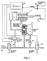
- a pneumatic actuator is indicated generally by reference character 11.
- Actuator 11 is of the single acting variety comprising a cylinder 13 and a piston 15 with a spring 17 being utilized to provide a restoring force to retract the piston when pressure to the left of the piston is reduced.
- the piston 15 is provided with a suitable position transducer, e.g. a slide wire potentiometer as indicated at 19, for generating a positional feedback signal.
- the feedback signal is provided to microprocessor servo control electronics designated generally by reference character 21.
- the functioning of the control electronics is described in greater detail hereinafter. However, at this point it is useful to note that the control electronics respond to the value of the feedback signal relative to an externally provided reference or set point signal, provided as indicated at reference character 22.
- Air or other gas under pressure is provided to the system through a supply line 23 from a suitable source, e.g. a compressor or tank of compressed gas.
- a suitable source e.g. a compressor or tank of compressed gas.
- the flow of gas from the supply is controlled by a simple ON/OFF solenoid valve 25.
- the section of conduit downstream of the solenoid valve 25 can also be selectively vented to the atmosphere through a second solenoid-operated valve 26 or can be selectively connected to the actuator cylinder through a third solenoid valve 27.
- the volume of the enclosure is utilized to control the amount of gas which is admitted or withdrawn from the actuator cylinder in a single step within an overall stepwise mode of operation. Accordingly, the volume contained by the enclosure is referred to herein as the step volume.
- the enclosure defining the step volume is illustrated as a small container or tank 31.
- the enclosure effectively includes not only the tank itself but also the associated connecting passageways. In some embodiments, connecting passages may constitute essentially the entire enclosure with no distinct tank or chamber being evident.
- a dual differential pressure regulator designated generally by reference character 32, to regulate or limit the pressure in the step volume as a predetermined function of the then extant pressure in the actuator.
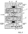
- a dual differential pressure regulator suitable for performing these functions is illustrated in fig. 2.
- the two regulator sections are of similar, though not identical, construction and are arranged in back-to-back fashion, as illustrated, with a common chamber 39 between them. Chamber 39 is connected directly to the actuator 11. This arrangement is appropriate since, as noted previously, each regulator operates to achieve a pressure in the tank 31, which is a function of the pressure in the actuator cylinder.
- Each regulator section comprises a pair of diaphragms.
- the proportionality between the regulated pressure and the actuator cylinder pressure is predetermined by the relative sizes of the operating areas of the two diaphragms in the respective regulator section.
- the upper regulator section 35 is the one which controls charging of the step volume.
- the upper diaphragm of regulator section 35 is designated by reference character 41 and has a smaller operative area than the lower diaphragm which is designated by reference character 43.
- the diaphragms 41 and 43 are separated at their central regions by a cylindrical spacer 45 which moves with the diaphragms in performing the regulating function and, at their periphery, by a ring-like spacer 47 which, with the peripheries is clamped between the upper regulator housing piece 51 and the middle regulator housing piece 53.
- a valving element 49 is carried by the central regions of the diaphragms 41 and 43, the valving element and a backing plate 48 being held by a bolt 50 which extends through the diaphragms 41 and 43 and the central spacer 45, thus causing the two diaphragms to be linked and to move together.
- a slight valve closing bias is provided by a spring 46.
- the space above the upper diaphragm is connected to the tank 31 through port 52 as indicated while the space below the lower diaphragm is connected to the actuator cylinder as described previously.
- the space between the two diaphragms is vented to atmosphere so as to be neutral in the regulator operation.
- the valving element 49 cooperates with a seat 57 machined into the upper regulator housing piece 51.
- the valving element controls venting of the space above the diaphragm 41 to the atmosphere.
- the spacer ring 47 is machined so that the operative region of the lower diaphragm 43 is larger than the operative region of the upper diaphragm.
- the tank pressure at which equilibrium is achieved is higher than the pressure in the actuator's cylinder, the proportionality between the pressures being determined by the relative active areas of the upper and lower diaphragms. If the pressure in the tank exceeds the equilibrium pressure, the valving element 49 lifts from the seat 57 venting some of the gas.
- the lower regulator section 37 is essentially similar to the upper regulator section 35 except that, in the lower section, the operative area of the diaphragm exposed to the actuator cylinder pressure is smaller than the active area of the diaphragm exposed to the pressure being regulated, i.e. the pressure in the tank 31. Accordingly, when the lower regulator section is in equilibrium, the regulated pressure in the tank will be smaller than the pressure in the actuator cylinder, the proportionality being determined by the relative active areas of the diaphragms 61 and 63.
- Fig. 2 also incorporates a check valve which provides the function of the check valve indicated by reference character 29 in Fig. 1.
- This check valve permits the conduit volume between the various solenoid valves to vent into the tank 31 while preventing flow in the opposite direction.
- this check valve is simply implemented by an O-ring 71 which rests in a frusto-conical recess 73 in the regulator bottom plate 75.
- the apparatus of the present invention achieves precision in operation by effecting charging and discharging of the actuator cylinder through an intermediate step volume, the pressure in the step volume in each case being regulated as a respective function of the then extant pressure in the actuator cylinder.
- the pressure in the step volume is established in one phase of operation and the transfer of gas between the step volume and the actuator occurs in a second phase.
- the overall operation is thus stepwise.
- the valves 25 and 27 are operated in alternation while in retracting the piston the valves 26 and 27 are operated in alternation.
- step volume defined by the capacity of tank 31 together with the associated conduits, is well defined, an essentially predetermined step movement of the piston 15 is obtained for a given position of the cylinder and for given pressures at the supply and in the capacity tank.
- the pressure to which the tank 31 is charged prior to the transfer to the actuator is regulated to a valve which is a function of the then extant pressure in the cylinder, the size of the step does not tend to vary as a function of load or spring bias as much as it would if the step volume were merely filled to a pressure which was only related to the supply presssure. In other words, a first order of compensation is obtained which to a considerable extent alleviates for the variable sensitivity of the actuator with the load.
- the volume of the capacity tank 31 should be allowed to vary in proportion with the actuator stroke as described hereinafter. However, for actuators of small to medium stroke, such a volume capacity compensation can be disregarded.
- valves 26 and 27 are operated alternately.
- gas in the tank 31 is vented to the atmosphere.
- the extent of venting is controlled by the lower pressure regulator section 37 so that venting is terminated when the pressure in the tank reaches a predetermined proportion of the pressure in the actuator cylinder, the proportionality factor being determined by the relative active areas of the two diaphragms as described previously.
- the valve 26 is closed and the valve 27 is open. With valve 27 open, gas flows from the actuator cylinder into the tank 31.
- the cycle of alternating operation of the valves can be repeated as needed to bring the piston to the desired position, i.e. a position at which the feedback signal is substantially equal to the set point signal.
- the rate at which the alternating cycles or steps are repeated is a design parameter which will depend on the particular application and load which the piston is to operate.
- the size of the movement which will occur with each step is in part a function of the size of the tank 31 and this also is a design parameter and the choice of value will depend upon the overall application.
- the arrangement in Fig. 1 provides compensation for the compressible nature of the gaseous medium being used for operating the actuator by allowing the size of the steps to be compensated by the then extant pressure in the actuator.
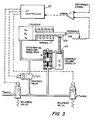
- Another parameter which enters into the effected step size is the active volume in the cylinder for the then extant position of the piston.
- a further degree of compensation is provided by causing the effective step volume to vary as a function of the position of the actuator piston.
- the step volume may be varied by means of a piston 101.
- the position of piston 101 is controlled by means of a follower 103 which is driven by means of a ramp or cam 105 which moves with the actuator piston 15. Accordingly, it can be seen that the step volume will vary as a function of actuator position, the step volume growing larger as the air volume in the cylinder grows larger.
- the differential pressure regulator provides control of the pressure to which the step volume is charged or discharged as in the previous embodiment but, since the step volume changes as a function of piston position, it can be seen that the amount of gas transferred to or from the actuator cylinder for each step is a function also of piston position. In other words, when the piston is to the left as shown, the amount of gas transferred for each step will be less since the volume in which it will be absorbed or distributed is also less. In this way, a second level of compensation is provided for the compressibility of the gaseous medium utilized to operate the actuator. As with a fixed volume capacity tank, the step size varies with the effective volume of the cylinder and the number of steps required to bring the piston to the desired position will vary automatically with the actuator stroke.
Landscapes
- Engineering & Computer Science (AREA)
- Chemical & Material Sciences (AREA)
- Analytical Chemistry (AREA)
- Physics & Mathematics (AREA)
- Fluid Mechanics (AREA)
- Mechanical Engineering (AREA)
- General Engineering & Computer Science (AREA)
- Fluid-Pressure Circuits (AREA)
- Servomotors (AREA)
- Actuator (AREA)
Claims (6)
- Vorrichtung zum Antreiben eines pneumatischen Stellgliedes (11) aus einer Gasquelle unter Druck und mit einer ersten Ventileinrichtung (25) zum Steuern der Zufuhr von Gas aus der Quelle und einer zweiten Ventileinrichtung (26) zum Steuern des Abblasens von Gas, wobei die Vorrichtung aufweist:
ein Gefäß (31), welches ein Schrittvolumen definiert, das an das Stellglied (11) zum Laden und Entlüften des Stellgliedes (11) durch das Gefäß hindurch anschließbar ist, wobei die erste und die zweite Ventileinrichtung (25, 26) zum selektiven Laden des Gefäßes (31) aus der Quelle bzw. zum selektiven Ablassen von Gas aus dem Gefäß (31) wirksam sind;
eine erste Drucksteuereinrichtung (35), die während des Ladens zum Steuern des Druckes in dem Gefäß (31) als eine vorbestimmte erste Funktion des dann in dem Stellglied (11) vorhandenen Druckes wirksam ist, wobei die erste Funktion einen Schrittvolumendruck vorsieht, der höher ist als der dann vorhandene Druck;
eine zweite Drucksteuereinrichtung (37) zum Steuern des Ablassens von Gas aus dem Gefäß (31) zur Begrenzung des Druckes in dem Gefäß (31) als eine zweite Funktion des dann in dem Stellglied (11) vorhandenen Druckes, wobei die zweite Funktion einen Schrittvolumendruck vorsieht, der niedriger als der Stellglieddruck ist; und
eine dritte Ventileinrichtung (27) zum selektiven Anschließen des Gefäßes (31) an das Stellglied (11), wobei die erste Ventileinrichtung (25) und die dritte Ventileinrichtung (27) abwechselnd zum Ausfahren des Stellgliedes (11) in Schritten betreibbar sind und die zweite Ventileinrichtung (26) und die dritte Ventileinrichtung abwechselnd zum Einfahren des Stellgliedes (11) in Schritten betreibbar sind. - Vorrichtung nach Anspruch 1, dadurch gekennzeichnet, daß das Gefäß (31), das ein Schrittvolumen definiert, mit dem Stellglied (11) zusammengeschaltet ist, um zu bewirken, daß das Schrittvolumen als Funktion der Stellgliedposition variiert.
- Vorrichtung nach Anspruch 1 oder 2, gekennzeichnet durch ein Rückschlagventil (29) zwischen dem Gefäß (31) und der zweiten Ventileinrichtung (26).
- Vorrichtung nach einem der vorhergehenden Ansprüche, dadurch gekennzeichnet, daß die erste Drucksteuereinrichtung (35) eine Differentialdrucksteuereinrichtung ist, die zum Entlüften des Schrittvolumens während des Ladens zur Begrenzung des Druckes in demselben als die erste vorbestimmte Funktion des Druckes in dem Stellglied (11) betreibbar ist.
- Vorrichtung nach einem der vorangehenden Ansprüche, gekennzeichnet durch mit dem Stellglied (11) verbundene Mittel zum Erzeugen eines Rückkopplungssignals, wobei die erste, die zweite und die dritte Ventileinrichtung in Antwort auf das Rückkopplungssignal zum Liefern einer Servosteuerung der Position des Stellgliedes in bezug auf ein extern geliefertes Sollwertsignal betreibbar sind.
- Vorrichtung nach einem der vorhergehenden Ansprüche, gekennzeichnet durch Mittel zum Variieren des Schrittvolumens als Funktion der Stellgliedverstellung.
Applications Claiming Priority (2)
| Application Number | Priority Date | Filing Date | Title |
|---|---|---|---|
| US908177 | 1986-09-17 | ||
| US06/908,177 US4741247A (en) | 1986-09-17 | 1986-09-17 | Pneumatic actuator apparatus |
Publications (3)
| Publication Number | Publication Date |
|---|---|
| EP0260935A2 EP0260935A2 (de) | 1988-03-23 |
| EP0260935A3 EP0260935A3 (en) | 1989-02-08 |
| EP0260935B1 true EP0260935B1 (de) | 1992-12-09 |
Family
ID=25425324
Family Applications (1)
| Application Number | Title | Priority Date | Filing Date |
|---|---|---|---|
| EP87308165A Expired EP0260935B1 (de) | 1986-09-17 | 1987-09-16 | Gerät für ein pneumatisches Stellglied |
Country Status (4)
| Country | Link |
|---|---|
| US (1) | US4741247A (de) |
| EP (1) | EP0260935B1 (de) |
| JP (1) | JPH07122442B2 (de) |
| DE (1) | DE3782993T2 (de) |
Families Citing this family (25)
| Publication number | Priority date | Publication date | Assignee | Title |
|---|---|---|---|---|
| US4903578A (en) * | 1988-07-08 | 1990-02-27 | Allied-Signal Inc. | Electropneumatic rotary actuator having proportional fluid valving |
| US4901625A (en) * | 1989-01-03 | 1990-02-20 | Increcyl, Inc. | Apparatus and method for positioning equipment |
| US5168703A (en) * | 1989-07-18 | 1992-12-08 | Jaromir Tobias | Continuously active pressure accumulator power transfer system |
| US5310017A (en) * | 1989-07-18 | 1994-05-10 | Jaromir Tobias | Vibration isolation support mounting system |
| US5012722A (en) * | 1989-11-06 | 1991-05-07 | International Servo Systems, Inc. | Floating coil servo valve |
| CH681380A5 (de) * | 1990-04-09 | 1993-03-15 | Asea Brown Boveri | |
| US5072648A (en) * | 1990-06-04 | 1991-12-17 | Caterpillar Industrial Inc. | Control system for a fluid operated jack |
| US5154207A (en) * | 1991-08-02 | 1992-10-13 | Mosier Industries, Inc. | Pressure control valve and transducer package |
| US5424941A (en) * | 1991-08-02 | 1995-06-13 | Mosier Industries, Inc. | Apparatus and method for positioning a pneumatic actuator |
| GB9416836D0 (en) * | 1994-08-19 | 1994-10-12 | Automotive Products Plc | Fluid pressure supply system |
| US5844390A (en) * | 1997-01-27 | 1998-12-01 | Cameron; Robert | Method and apparatus for regulating a fluid operated machine |
| IT1294650B1 (it) * | 1997-09-08 | 1999-04-12 | Special Springs Srl | Gruppo di comando e di alimentazione particolarmente per attuatori ausiliari atti alla movimentazione di attrezzature e/o utensili |
| US6356811B1 (en) * | 1998-10-13 | 2002-03-12 | Honeywell Measurex Devron Inc. | Control system for pneumatic actuators |
| WO2001031205A1 (en) | 1999-10-27 | 2001-05-03 | Tol-O-Matic, Inc. | Precision servo control system for a pneumatic actuator |
| US6598391B2 (en) | 2001-08-28 | 2003-07-29 | Caterpillar Inc | Control for electro-hydraulic valve arrangement |
| DE10210877A1 (de) * | 2002-03-12 | 2003-11-27 | Wabco Gmbh & Co Ohg | Ventileinrichtung für Stellzylinder |
| US7040349B2 (en) * | 2002-03-27 | 2006-05-09 | Viking Technologies, L.C. | Piezo-electric actuated multi-valve manifold |
| US7021191B2 (en) * | 2003-01-24 | 2006-04-04 | Viking Technologies, L.C. | Accurate fluid operated cylinder positioning system |
| GB2416425B (en) | 2003-04-04 | 2007-01-03 | Viking Technologies Lc | Apparatus and process for optimizing work from a smart material actuator product |
| JP4353334B2 (ja) * | 2007-03-30 | 2009-10-28 | Smc株式会社 | 単動形エアシリンダの位置決め制御機構 |
| US7958768B2 (en) * | 2008-06-24 | 2011-06-14 | Fluke Corporation | System to control pressure in a test device |
| DE102009044930A1 (de) * | 2009-09-24 | 2011-04-07 | Ernst Beck | Gasexpansionsmotor |
| WO2012011417A1 (ja) | 2010-07-23 | 2012-01-26 | Takasu Shuhei | 整復技術習得用の人体模型教材および該人体模型教材を用いた整復技術の習得方法 |
| US9129535B2 (en) | 2010-07-23 | 2015-09-08 | Shuhei Takasu | Anatomical model for training aid for learning reduction techniques and a method for learning the reduction techniques using the anatomical model for training aid |
| RU2714987C1 (ru) * | 2019-06-04 | 2020-02-21 | Общество с ограниченной ответственностью "Камоцци Пневматика" | Пневматический привод с цилиндром одностороннего действия |
Family Cites Families (12)
| Publication number | Priority date | Publication date | Assignee | Title |
|---|---|---|---|---|
| CH365233A (de) * | 1958-11-07 | 1962-10-31 | Ibm | Verfahren und Maschine zum wiederholten Weiterbewegen eines Gegenstandes mittels eines durch das Verdrängen einer bestimmten Menge einer Flüssigkeit betätigten Kolbens |
| GB1160451A (en) * | 1966-02-22 | 1969-08-06 | Coal Industry Patents Ltd | Fixed Increment Advance of Face Conveyors |
| US3382769A (en) * | 1966-04-04 | 1968-05-14 | Navy Usa | Digital hydraulic actuator |
| US3538814A (en) * | 1967-12-15 | 1970-11-10 | Earl H Fisher | Double-acting hydraulic cylinder and control therefor |
| US3795110A (en) * | 1972-12-07 | 1974-03-05 | J Kobelt | Multiple-station fluid control circuit |
| FR2213428B1 (de) * | 1973-01-09 | 1976-04-30 | Dba | |
| FR2270468A1 (en) * | 1974-03-04 | 1975-12-05 | Alsthom Cgee | Hydraulic ram indexing system - connects ram to higher-pressure side of piston in hydraulic vessel |
| US4077738A (en) * | 1975-12-29 | 1978-03-07 | Teledyne Industries, Inc. | Time modulated position controller |
| US4450753A (en) * | 1980-05-12 | 1984-05-29 | Ford Motor Company | Electro-hydraulic proportional actuator |
| US4437385A (en) * | 1982-04-01 | 1984-03-20 | Deere & Company | Electrohydraulic valve system |
| US4481451A (en) * | 1982-08-20 | 1984-11-06 | Johnson Service Company | Electronically controlled positioner for pneumatic actuators |
| JPS60231004A (ja) * | 1984-04-27 | 1985-11-16 | Honda Motor Co Ltd | 圧力応動型アクチユエ−タの制御装置 |
-
1986
- 1986-09-17 US US06/908,177 patent/US4741247A/en not_active Expired - Lifetime
-
1987
- 1987-09-16 DE DE8787308165T patent/DE3782993T2/de not_active Expired - Fee Related
- 1987-09-16 EP EP87308165A patent/EP0260935B1/de not_active Expired
- 1987-09-17 JP JP62234690A patent/JPH07122442B2/ja not_active Expired - Fee Related
Also Published As
| Publication number | Publication date |
|---|---|
| DE3782993D1 (de) | 1993-01-21 |
| US4741247A (en) | 1988-05-03 |
| JPS63167102A (ja) | 1988-07-11 |
| DE3782993T2 (de) | 1993-07-08 |
| EP0260935A2 (de) | 1988-03-23 |
| JPH07122442B2 (ja) | 1995-12-25 |
| EP0260935A3 (en) | 1989-02-08 |
Similar Documents
| Publication | Publication Date | Title |
|---|---|---|
| EP0260935B1 (de) | Gerät für ein pneumatisches Stellglied | |
| SU776574A3 (ru) | Клапанный переключатель | |
| US5586575A (en) | Electropneumatic converter with solenoid valve control | |
| US7163025B2 (en) | Vacuum regulating valve | |
| JP4102329B2 (ja) | 正圧及び負圧を送り出す能力を備えた比例型圧力調整器 | |
| US4531548A (en) | Apparatus to vary the force exerted on an actuator mechanism | |
| GB1417931A (en) | Control valves | |
| US3200713A (en) | Hydraulic servo-mechanism | |
| US6047728A (en) | Spring loaded bellows regulator | |
| US4744542A (en) | Hydraulic control apparatus | |
| CN213744225U (zh) | 一种液压泵功率控制器 | |
| US4971104A (en) | Self powered servo actuated backpressure regulating valve | |
| GB2201735A (en) | A control system for a rotary compressor | |
| US2817318A (en) | Fluid pressure controlled positioners for fluid operated motors | |
| JPH0341123Y2 (de) | ||
| JPS6324489Y2 (de) | ||
| US3221501A (en) | Power matched hydraulic servo-system | |
| JPS61214012A (ja) | 圧力制御弁 | |
| JPH0446201A (ja) | 空圧シリンダ用切換弁 | |
| SU1078411A1 (ru) | Регул тор давлени газа | |
| WO2024261621A1 (en) | An improvded gas regulator | |
| GB1204874A (en) | Compressed fluid operated control valve actuators | |
| RU1830522C (ru) | Регул тор давлени газа | |
| JP2665822B2 (ja) | 減圧弁 | |
| SU809099A1 (ru) | Двухступенчатый регул тор давлени |
Legal Events
| Date | Code | Title | Description |
|---|---|---|---|
| PUAI | Public reference made under article 153(3) epc to a published international application that has entered the european phase |
Free format text: ORIGINAL CODE: 0009012 |
|
| AK | Designated contracting states |
Kind code of ref document: A2 Designated state(s): DE FR GB IT |
|
| PUAL | Search report despatched |
Free format text: ORIGINAL CODE: 0009013 |
|
| AK | Designated contracting states |
Kind code of ref document: A3 Designated state(s): DE FR GB IT |
|
| 17P | Request for examination filed |
Effective date: 19890807 |
|
| 17Q | First examination report despatched |
Effective date: 19910108 |
|
| GRAA | (expected) grant |
Free format text: ORIGINAL CODE: 0009210 |
|
| AK | Designated contracting states |
Kind code of ref document: B1 Designated state(s): DE FR GB IT |
|
| PG25 | Lapsed in a contracting state [announced via postgrant information from national office to epo] |
Ref country code: IT Free format text: LAPSE BECAUSE OF FAILURE TO SUBMIT A TRANSLATION OF THE DESCRIPTION OR TO PAY THE FEE WITHIN THE PRE;WARNING: LAPSES OF ITALIAN PATENTS WITH EFFECTIVE DATE BEFORE 2007 MAY HAVE OCCURRED AT ANY TIME BEFORE 2007. THE CORRECT EFFECTIVE DATE MAY BE DIFFERENT FROM THE ONE RECORDED.SCRIBED TIME-LIMIT Effective date: 19921209 |
|
| REF | Corresponds to: |
Ref document number: 3782993 Country of ref document: DE Date of ref document: 19930121 |
|
| ET | Fr: translation filed | ||
| PLBE | No opposition filed within time limit |
Free format text: ORIGINAL CODE: 0009261 |
|
| STAA | Information on the status of an ep patent application or granted ep patent |
Free format text: STATUS: NO OPPOSITION FILED WITHIN TIME LIMIT |
|
| 26N | No opposition filed | ||
| REG | Reference to a national code |
Ref country code: GB Ref legal event code: IF02 |
|
| PGFP | Annual fee paid to national office [announced via postgrant information from national office to epo] |
Ref country code: GB Payment date: 20030912 Year of fee payment: 17 |
|
| PGFP | Annual fee paid to national office [announced via postgrant information from national office to epo] |
Ref country code: FR Payment date: 20030930 Year of fee payment: 17 |
|
| PGFP | Annual fee paid to national office [announced via postgrant information from national office to epo] |
Ref country code: DE Payment date: 20031031 Year of fee payment: 17 |
|
| PG25 | Lapsed in a contracting state [announced via postgrant information from national office to epo] |
Ref country code: GB Free format text: LAPSE BECAUSE OF NON-PAYMENT OF DUE FEES Effective date: 20040916 |
|
| PG25 | Lapsed in a contracting state [announced via postgrant information from national office to epo] |
Ref country code: DE Free format text: LAPSE BECAUSE OF NON-PAYMENT OF DUE FEES Effective date: 20050401 |
|
| GBPC | Gb: european patent ceased through non-payment of renewal fee |
Effective date: 20040916 |
|
| PG25 | Lapsed in a contracting state [announced via postgrant information from national office to epo] |
Ref country code: FR Free format text: LAPSE BECAUSE OF NON-PAYMENT OF DUE FEES Effective date: 20050531 |
|
| REG | Reference to a national code |
Ref country code: FR Ref legal event code: ST |