EP0259926A1 - Schmelzsicherung - Google Patents
Schmelzsicherung Download PDFInfo
- Publication number
- EP0259926A1 EP0259926A1 EP87201676A EP87201676A EP0259926A1 EP 0259926 A1 EP0259926 A1 EP 0259926A1 EP 87201676 A EP87201676 A EP 87201676A EP 87201676 A EP87201676 A EP 87201676A EP 0259926 A1 EP0259926 A1 EP 0259926A1
- Authority
- EP
- European Patent Office
- Prior art keywords
- fuse
- strip
- housing
- link
- link strip
- Prior art date
- Legal status (The legal status is an assumption and is not a legal conclusion. Google has not performed a legal analysis and makes no representation as to the accuracy of the status listed.)
- Granted
Links
Images


Classifications
-
- H—ELECTRICITY
- H01—ELECTRIC ELEMENTS
- H01H—ELECTRIC SWITCHES; RELAYS; SELECTORS; EMERGENCY PROTECTIVE DEVICES
- H01H85/00—Protective devices in which the current flows through a part of fusible material and this current is interrupted by displacement of the fusible material when this current becomes excessive
- H01H85/02—Details
- H01H85/04—Fuses, i.e. expendable parts of the protective device, e.g. cartridges
- H01H85/041—Fuses, i.e. expendable parts of the protective device, e.g. cartridges characterised by the type
- H01H85/0411—Miniature fuses
- H01H85/0415—Miniature fuses cartridge type
- H01H85/0417—Miniature fuses cartridge type with parallel side contacts
Definitions
- This invention relates to a blade-type fuse.
- a prior device of the type to which the present invention relates is known, for example, from U.S. patent 4,344,060, and comprises a housing of an electrically insulating material and a fuse element disposed within said housing, said fuse element comprising two spaced metallic strip or blade terminals having ends projecting beyond the housing, and a metallic link strip interconnecting said two terminals, said link strip being disposed to extend virtually freely in a space within the housing, and being designed to fuse if current of an intensity exceeding a permissible value is passed through it for a certain time. Fuses of this type are frequently being used in the automobile industry.
- the prior fuse is, in operation, often used so that the contact blades and the link strip lie in a horizontal plane.
- the construction is such that the link strip fuses upon a prolonged passage of current having an intensity slightly in excess of the nominal value determined for the fuse, or upon the passage of a current having a very high intensity (short-circuiting current).
- the temperature of the link strip will increase progressively until the strip melts. The increase in temperature is the result of the dissipation of electric power into the material as a result of the passage of electric current through it.
- the amount of heat dissipated into the link strip will not be so high that a portion of the strip will fuse or become soft, or becomes excessively longer from thermal expansion. Heat generated in the strip is dissipated into the adjoining strip terminals, the housing, and the panel in which the fuse is mounted. When a current in excess of the nominal current intensity passes through the strip, the amount of heat generated will be so high that insufficient heat can be dissipated via the strip terminals and the housing, so that the temperature will increase to above the fusing temperature. Prior to fusing, the link strip will become softened.
- a fuse comprising means for preventing sagging of the link strip upon heating such as would prevent it from operating properly.
- the means provided in accordance with the present invention may be of two kinds.
- the means referred to comprise projections extending into said space from the wall of the housing toward the link strip, said projections supporting the link strip either permanently or upon initial sagging.
- the means for preventing sagging of the link strip comprise provisions on the link strip proper.
- the provisions on the link strip comprise melting point reducing means in combination with means for concentrating the fusing at a pre-determined place.
- the melting point reducing means are tin beads
- the fusing concentrating means are reductions in size of the strip, holes in the strip, or holes in the strip combined with thickened portions around the holes.
- a hollow staple of tin is provided in link strip of zinc, and a plug of copper is disposed in the cavity of the hollow staple, which plug is supported by, or closely spaced from, a projection from the wall of the housing.
- the link strip is made of copper in two parts interconnected by a tin bead provided by an extrusion-riveting technique.
- the fuse can be made slower or less slow.
- the material for the blade terminals may be the same as the material for the link strip. In that case, terminals and link strip may be made in one integral piece. This is not necessary, however. In the case of separate terminals and link strip, the connection between these members may be effected in a suitable manner by an extrusion-riveting technique.
- a suitable material for the blade terminals is tinned brass, in view of its low price.
- this material is less desirable, in view of its relatively high melting temperature.
- a material suitable for both types of strips, for example, is zinc coated with a copper layer and/or a tin layer.
- Fig. 1 is an exploded view of the fuse according to the present invention.
- the fuse comprises a housing 1 of suitable plastics material and a fuse element 2 of metal.
- housing 1 is of generally rectangular shape, determined by the relatively closely spaced opposed larger sidewalls 3 and 4 which interconnect the smaller sidewalls 5 and 6.
- the top is defined by top wall 7.
- the less deeply recessed portions 18 and 19 of walls 3 and 4 leave a space 20 in housing 1, in which, after the introduction of the fuse element 2 into the housing the link strip 21 is disposed to extend virtually freely.
- a strip-shaped extension 22 which after the introduction of the fuse element into the housing can be folded to rest against the lower end of the recessed wall portion 18, so that space 20 is closed at the bottom.
- the link strip 21 of fuse element 2 is shown in Fig. 1 as being formed integrally with the blade terminals 12 and 13. This, however, is not absolutely necessary.
- the link strip which is the fuse element proper, may be a separate strip connected with the terminals in a suitable manner. Although soldering and welding are possible techniques for connecting a separate link strip, an extrusion-riveting technique is preferred.
- a separate link strip may be desirable in connection with the choice of the material to be used.
- a material which is highly suitable for use as a link strip material on the ground of melting characteristics and the like, may be less attractive for the blade terminals on the ground of economic considerations.
- the means for preventing the sagging of link strip 21 in the case of increased generation of heat during operation comprise a pair of projections 23, 24 extending from the respective inner surfaces of the recessed portions 18 and 19 in the direction of link strip 21.
- Projections 23 and 24, which in the embodiment shown have the shape of cones, may touch link strip 21, or extend just short of this strip.
- the first case during operation, as soon as heat is generated in strip 21, they will already be able to dissipate a small part thereof (in view of the point contact).
- such a dissipation does not take place until after link strip 21 has begun to sag, and the tip of one of the conical projections 23, 24 touches strip 21.
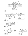
- Figs. 3 et seq. various embodiments of the fuse according to the invention are shown in detail.They are shown diagrammatically only. Thus Figs. 3, 4 and 5 all show a straight link strip between straight blade terminals. It will be clear, however, that both the terminals and the link strip may have any suitable form, in particular that shown in Fig. 1.
- the link strip and the blade terminals may be formed in one piece or constitute separate parts interconnected in a suitable manner.
- the link strip 31 is provided between blade terminals 32 and 33 with a pair of holes 34 and 35 punched into it.
- a tin bead 36 Provided between holes 34 and 35 is a tin bead 36.
- the temperature of the portion of strip 31 between holes 34 and 35 is kept at a value which will not exceed a pre-determined maximum owing to the presence of the tin between the holes. This maximum will be approximately the melting temperature of tin. Owing to the holes, the heat transmission from the portion between the holes to the portion of the strip 31 between each hole and the adjacent blade terminal is limited.
- the portion between holes 34 and 35 will have a virtually constant temperature prior to the possible fusing, which constant temperature will hardly, if at all, be higher than the melting temperature of tin. There is practically no risk of sagging in that configuration.
- Fig. 4 shows a variant in which strip 41 linking blade terminals 42 and 43 has two tin beads 44 and 45 spaced some distance apart. Between the tin beads 44 and 45 a hole 46 has been punched in strip 41. Owing to the provision of tin beads 44 and 45, in operation, the temperature of the strip between and around the beads will not exceed a value determined by the melting temperature of the tin. Hole 46 amounts to a reduction in size of strip 41, so that the strip is most likely to fuse at that point. Owing to the limited temperature, there is virtually no risk of sagging.
- Fig. 5 shows a variant of the embodiment of Fig. 3.
- Strip 51 connects blade terminals 52 and 53.
- a tin bead 56 is provided in the middle of strip 51.
- reductions 54 and 55 are provided in strip 51, which have a function similar to holes 34 and 35 in Fig. 3.
- Fig. 6 illustrates a different solution for the sagging problem.
- Link strip 61 of zinc is provided at a suitable location, for example in the middle, with a hollow staple 62 of tin.
- a plug 63 for example of copper.
- this plug is kept in position by conical projections 64 and 65 directed inwardly from the inner surface 66, 67 of the wall of the housing of the fuse.
- the hollow staple 62 of tin serves as a melting point reducing means, by virtue of which strip 61 of zinc does not become so hot that it will sag.
- the copper plug 63 with projections 65 and 64 operate as an additional heat sink and as an additional heat capacity.
- Figs. 7A-7B show another variant which is not dissimilar to the embodiment of Fig. 3.
- the link strip 71 is provided with two spaced holes 72 and 73 with a tin bead 74 provided between them.
- the difference from the variant of Fig. 3 is that thickenings or collars 75, 76 are provided around the holes, which increases the heat capacity. Such thickenings may alternatively be provided separately without the presence of holes.
- Figs. 8A-8B show still another variant.
- the link strip consists of two parts 81 and 82 interconnected by means of a bead of material provided with the help of an extrusion-riveting method.
- Parts 81 and 82 of the link strip consist, for example, of copper and the bead 83 of tin.
- This bead has a melting point reducing effect, by virtue of which the fusing temperature cannot become so high as to cause sagging.
Landscapes
- Fuses (AREA)
Applications Claiming Priority (2)
| Application Number | Priority Date | Filing Date | Title |
|---|---|---|---|
| NL8602252A NL8602252A (nl) | 1986-09-05 | 1986-09-05 | Smeltveiligheid. |
| NL8602252 | 1986-09-05 |
Publications (2)
| Publication Number | Publication Date |
|---|---|
| EP0259926A1 true EP0259926A1 (de) | 1988-03-16 |
| EP0259926B1 EP0259926B1 (de) | 1993-03-10 |
Family
ID=19848509
Family Applications (1)
| Application Number | Title | Priority Date | Filing Date |
|---|---|---|---|
| EP19870201676 Expired - Lifetime EP0259926B1 (de) | 1986-09-05 | 1987-09-04 | Schmelzsicherung |
Country Status (4)
| Country | Link |
|---|---|
| EP (1) | EP0259926B1 (de) |
| DE (1) | DE3784601T2 (de) |
| ES (1) | ES2038167T3 (de) |
| NL (1) | NL8602252A (de) |
Cited By (3)
| Publication number | Priority date | Publication date | Assignee | Title |
|---|---|---|---|---|
| US5239282A (en) * | 1991-10-09 | 1993-08-24 | Amp Incorporated | Electrical blade fuse |
| EP0911853A1 (de) * | 1997-10-23 | 1999-04-28 | Roar Korzsinek | Sicherungseinheit mit Ansprechanzeiger |
| CN105340046A (zh) * | 2013-07-12 | 2016-02-17 | 太平洋精工株式会社 | 熔丝 |
Families Citing this family (1)
| Publication number | Priority date | Publication date | Assignee | Title |
|---|---|---|---|---|
| DE4447731C2 (de) * | 1994-11-19 | 1999-06-10 | Grote & Hartmann | Steckverbinder |
Citations (10)
| Publication number | Priority date | Publication date | Assignee | Title |
|---|---|---|---|---|
| GB439517A (en) * | 1934-06-15 | 1935-12-09 | John Ashworth Crabtree | Improvements in, or relating to, fusible electric cut-outs |
| US2143031A (en) * | 1935-03-07 | 1939-01-10 | Gen Electric | Enclosed fuse |
| DE723352C (de) * | 1941-03-16 | 1942-08-03 | Eduard Gruenwald | Schmelzleiteranordnung in Sicherungspatronen |
| US2688061A (en) * | 1952-08-16 | 1954-08-31 | Chase Shawmut Co | Time lag fuse |
| GB777057A (en) * | 1954-05-05 | 1957-06-19 | Parmiter Hope & Sugden Ltd | Improvements in and relating to electric fuses |
| DE1910594A1 (de) * | 1969-03-01 | 1970-09-10 | Carl Braun Camera Werk Fa | Sicherheitsskibindung fuer Absatzhalterung |
| DE2949432A1 (de) * | 1979-12-08 | 1981-06-11 | Georg Rudolf 8411 Zeitlarn Sillner | Mehrteilige stecksicherung |
| GB2090081A (en) * | 1980-12-08 | 1982-06-30 | Bosley Sydney Stanley | Plug-in and in-line electrical fuses |
| US4344060A (en) * | 1980-09-19 | 1982-08-10 | Littelfuse, Inc. | Enclosed plug-in fuse assembly |
| US4635023A (en) * | 1985-05-22 | 1987-01-06 | Littelfuse, Inc. | Fuse assembly having a non-sagging suspended fuse link |
-
1986
- 1986-09-05 NL NL8602252A patent/NL8602252A/nl not_active Application Discontinuation
-
1987
- 1987-09-04 ES ES87201676T patent/ES2038167T3/es not_active Expired - Lifetime
- 1987-09-04 EP EP19870201676 patent/EP0259926B1/de not_active Expired - Lifetime
- 1987-09-04 DE DE19873784601 patent/DE3784601T2/de not_active Expired - Lifetime
Patent Citations (10)
| Publication number | Priority date | Publication date | Assignee | Title |
|---|---|---|---|---|
| GB439517A (en) * | 1934-06-15 | 1935-12-09 | John Ashworth Crabtree | Improvements in, or relating to, fusible electric cut-outs |
| US2143031A (en) * | 1935-03-07 | 1939-01-10 | Gen Electric | Enclosed fuse |
| DE723352C (de) * | 1941-03-16 | 1942-08-03 | Eduard Gruenwald | Schmelzleiteranordnung in Sicherungspatronen |
| US2688061A (en) * | 1952-08-16 | 1954-08-31 | Chase Shawmut Co | Time lag fuse |
| GB777057A (en) * | 1954-05-05 | 1957-06-19 | Parmiter Hope & Sugden Ltd | Improvements in and relating to electric fuses |
| DE1910594A1 (de) * | 1969-03-01 | 1970-09-10 | Carl Braun Camera Werk Fa | Sicherheitsskibindung fuer Absatzhalterung |
| DE2949432A1 (de) * | 1979-12-08 | 1981-06-11 | Georg Rudolf 8411 Zeitlarn Sillner | Mehrteilige stecksicherung |
| US4344060A (en) * | 1980-09-19 | 1982-08-10 | Littelfuse, Inc. | Enclosed plug-in fuse assembly |
| GB2090081A (en) * | 1980-12-08 | 1982-06-30 | Bosley Sydney Stanley | Plug-in and in-line electrical fuses |
| US4635023A (en) * | 1985-05-22 | 1987-01-06 | Littelfuse, Inc. | Fuse assembly having a non-sagging suspended fuse link |
Cited By (5)
| Publication number | Priority date | Publication date | Assignee | Title |
|---|---|---|---|---|
| US5239282A (en) * | 1991-10-09 | 1993-08-24 | Amp Incorporated | Electrical blade fuse |
| EP0911853A1 (de) * | 1997-10-23 | 1999-04-28 | Roar Korzsinek | Sicherungseinheit mit Ansprechanzeiger |
| CN105340046A (zh) * | 2013-07-12 | 2016-02-17 | 太平洋精工株式会社 | 熔丝 |
| EP3021345A4 (de) * | 2013-07-12 | 2017-02-15 | Pacific Engineering Corporation | Sicherung |
| US10283305B2 (en) | 2013-07-12 | 2019-05-07 | Pacific Engineering Corporation | Fuse |
Also Published As
| Publication number | Publication date |
|---|---|
| EP0259926B1 (de) | 1993-03-10 |
| NL8602252A (nl) | 1988-04-05 |
| DE3784601T2 (de) | 1993-06-17 |
| ES2038167T3 (es) | 1993-07-16 |
| DE3784601D1 (de) | 1993-04-15 |
Similar Documents
| Publication | Publication Date | Title |
|---|---|---|
| KR0144438B1 (ko) | 칩 퓨즈 | |
| US4131869A (en) | Plug-in fuse assembly construction | |
| EP0039562B1 (de) | Schmelzsicherung | |
| EP0544521B1 (de) | Klemme zum Anschluss von Drähten | |
| US5101187A (en) | Subminiature fuse and method of manufacturing same | |
| US4972170A (en) | High speed fuse | |
| JPH0731976B2 (ja) | 垂下防止手段付吊橋状ヒュ−ズリンクを有するヒュ−ズアッセンブリ | |
| EP0233136A2 (de) | Heizelementaufbau für Wassererhitzer | |
| JP3377031B2 (ja) | 回路保護素子の接続構造 | |
| EP0633592A1 (de) | Anschlussklemme für Sicherung | |
| JPS6161331A (ja) | 差込式ヒユーズ装置 | |
| EP0631294A2 (de) | Sicherung | |
| JPH06504875A (ja) | 高定格電流用平形ヒューズ | |
| US4056884A (en) | Method of making a miniature plug-in fuse | |
| EP0259926B1 (de) | Schmelzsicherung | |
| US5821847A (en) | Fuse and method of manufacturing same | |
| US4951026A (en) | Weld projections on fuse terminals | |
| US4949063A (en) | End closure system for high speed fuse | |
| US4040175A (en) | Method of making a miniature plug-in fuse with fragile fuse link | |
| CA1116665A (en) | Fuse clip for a cartridge fuseholder | |
| TW202133207A (zh) | 限流保險絲 | |
| EP0778603B1 (de) | Flachsicherung und Verfahren zu ihrer Herstellung | |
| US4651119A (en) | Electric fuse heat dam element having stiffening ribs | |
| US5362242A (en) | Junction box and terminal to be used in the junction box | |
| US3206579A (en) | Fuse and method of manufacture |
Legal Events
| Date | Code | Title | Description |
|---|---|---|---|
| PUAI | Public reference made under article 153(3) epc to a published international application that has entered the european phase |
Free format text: ORIGINAL CODE: 0009012 |
|
| AK | Designated contracting states |
Kind code of ref document: A1 Designated state(s): BE CH DE ES FR GB IT LI LU NL SE |
|
| 17P | Request for examination filed |
Effective date: 19880811 |
|
| 17Q | First examination report despatched |
Effective date: 19910419 |
|
| GRAA | (expected) grant |
Free format text: ORIGINAL CODE: 0009210 |
|
| AK | Designated contracting states |
Kind code of ref document: B1 Designated state(s): BE CH DE ES FR GB IT LI LU NL SE |
|
| REF | Corresponds to: |
Ref document number: 3784601 Country of ref document: DE Date of ref document: 19930415 |
|
| ET | Fr: translation filed | ||
| ITF | It: translation for a ep patent filed |
Owner name: SOCIETA' ITALIANA BREVETTI S.P.A. |
|
| REG | Reference to a national code |
Ref country code: ES Ref legal event code: FG2A Ref document number: 2038167 Country of ref document: ES Kind code of ref document: T3 |
|
| EPTA | Lu: last paid annual fee | ||
| PLBE | No opposition filed within time limit |
Free format text: ORIGINAL CODE: 0009261 |
|
| STAA | Information on the status of an ep patent application or granted ep patent |
Free format text: STATUS: NO OPPOSITION FILED WITHIN TIME LIMIT |
|
| 26N | No opposition filed | ||
| EAL | Se: european patent in force in sweden |
Ref document number: 87201676.1 |
|
| PGFP | Annual fee paid to national office [announced via postgrant information from national office to epo] |
Ref country code: GB Payment date: 20000831 Year of fee payment: 14 |
|
| PGFP | Annual fee paid to national office [announced via postgrant information from national office to epo] |
Ref country code: LU Payment date: 20000906 Year of fee payment: 14 |
|
| PGFP | Annual fee paid to national office [announced via postgrant information from national office to epo] |
Ref country code: CH Payment date: 20000911 Year of fee payment: 14 |
|
| PGFP | Annual fee paid to national office [announced via postgrant information from national office to epo] |
Ref country code: SE Payment date: 20000918 Year of fee payment: 14 |
|
| PGFP | Annual fee paid to national office [announced via postgrant information from national office to epo] |
Ref country code: NL Payment date: 20000930 Year of fee payment: 14 |
|
| PGFP | Annual fee paid to national office [announced via postgrant information from national office to epo] |
Ref country code: ES Payment date: 20001005 Year of fee payment: 14 |
|
| PGFP | Annual fee paid to national office [announced via postgrant information from national office to epo] |
Ref country code: BE Payment date: 20001017 Year of fee payment: 14 |
|
| PG25 | Lapsed in a contracting state [announced via postgrant information from national office to epo] |
Ref country code: LU Free format text: LAPSE BECAUSE OF NON-PAYMENT OF DUE FEES Effective date: 20010904 Ref country code: GB Free format text: LAPSE BECAUSE OF NON-PAYMENT OF DUE FEES Effective date: 20010904 |
|
| PG25 | Lapsed in a contracting state [announced via postgrant information from national office to epo] |
Ref country code: SE Free format text: LAPSE BECAUSE OF NON-PAYMENT OF DUE FEES Effective date: 20010905 Ref country code: ES Free format text: LAPSE BECAUSE OF NON-PAYMENT OF DUE FEES Effective date: 20010905 |
|
| PG25 | Lapsed in a contracting state [announced via postgrant information from national office to epo] |
Ref country code: LI Free format text: LAPSE BECAUSE OF NON-PAYMENT OF DUE FEES Effective date: 20010930 Ref country code: CH Free format text: LAPSE BECAUSE OF NON-PAYMENT OF DUE FEES Effective date: 20010930 Ref country code: BE Free format text: LAPSE BECAUSE OF NON-PAYMENT OF DUE FEES Effective date: 20010930 |
|
| BERE | Be: lapsed |
Owner name: LITTELFUSE TRACOR B.V. Effective date: 20010930 |
|
| PG25 | Lapsed in a contracting state [announced via postgrant information from national office to epo] |
Ref country code: NL Free format text: LAPSE BECAUSE OF NON-PAYMENT OF DUE FEES Effective date: 20020401 |
|
| EUG | Se: european patent has lapsed |
Ref document number: 87201676.1 |
|
| REG | Reference to a national code |
Ref country code: CH Ref legal event code: PL |
|
| NLV4 | Nl: lapsed or anulled due to non-payment of the annual fee |
Effective date: 20020401 |
|
| NLV4 | Nl: lapsed or anulled due to non-payment of the annual fee |
Effective date: 20020401 |
|
| REG | Reference to a national code |
Ref country code: ES Ref legal event code: FD2A Effective date: 20021011 |
|
| PGFP | Annual fee paid to national office [announced via postgrant information from national office to epo] |
Ref country code: FR Payment date: 20060831 Year of fee payment: 20 |
|
| PGFP | Annual fee paid to national office [announced via postgrant information from national office to epo] |
Ref country code: IT Payment date: 20060930 Year of fee payment: 20 |
|
| PGFP | Annual fee paid to national office [announced via postgrant information from national office to epo] |
Ref country code: DE Payment date: 20061128 Year of fee payment: 20 |