EP0259028A2 - Gerät zur Formung eines handförmigen Elektronenstrahls - Google Patents
Gerät zur Formung eines handförmigen Elektronenstrahls Download PDFInfo
- Publication number
- EP0259028A2 EP0259028A2 EP87307062A EP87307062A EP0259028A2 EP 0259028 A2 EP0259028 A2 EP 0259028A2 EP 87307062 A EP87307062 A EP 87307062A EP 87307062 A EP87307062 A EP 87307062A EP 0259028 A2 EP0259028 A2 EP 0259028A2
- Authority
- EP
- European Patent Office
- Prior art keywords
- electron beam
- slot
- thyratron
- arrangement
- beam sheet
- Prior art date
- Legal status (The legal status is an assumption and is not a legal conclusion. Google has not performed a legal analysis and makes no representation as to the accuracy of the status listed.)
- Withdrawn
Links
- 238000010894 electron beam technology Methods 0.000 title claims abstract description 41
- 208000028659 discharge Diseases 0.000 claims description 11
- 239000000463 material Substances 0.000 claims description 2
- 239000002184 metal Substances 0.000 claims description 2
- 238000005086 pumping Methods 0.000 claims description 2
- 238000004519 manufacturing process Methods 0.000 claims 1
- 239000007789 gas Substances 0.000 description 5
- 239000012777 electrically insulating material Substances 0.000 description 3
- 239000000919 ceramic Substances 0.000 description 2
- UFHFLCQGNIYNRP-UHFFFAOYSA-N Hydrogen Chemical compound [H][H] UFHFLCQGNIYNRP-UHFFFAOYSA-N 0.000 description 1
- 230000015556 catabolic process Effects 0.000 description 1
- 230000007423 decrease Effects 0.000 description 1
- 230000005284 excitation Effects 0.000 description 1
- 239000011810 insulating material Substances 0.000 description 1
- 150000002500 ions Chemical class 0.000 description 1
- 238000000034 method Methods 0.000 description 1
Images

Classifications
-
- H—ELECTRICITY
- H01—ELECTRIC ELEMENTS
- H01S—DEVICES USING THE PROCESS OF LIGHT AMPLIFICATION BY STIMULATED EMISSION OF RADIATION [LASER] TO AMPLIFY OR GENERATE LIGHT; DEVICES USING STIMULATED EMISSION OF ELECTROMAGNETIC RADIATION IN WAVE RANGES OTHER THAN OPTICAL
- H01S3/00—Lasers, i.e. devices using stimulated emission of electromagnetic radiation in the infrared, visible or ultraviolet wave range
- H01S3/09—Processes or apparatus for excitation, e.g. pumping
- H01S3/0955—Processes or apparatus for excitation, e.g. pumping using pumping by high energy particles
- H01S3/0959—Processes or apparatus for excitation, e.g. pumping using pumping by high energy particles by an electron beam
-
- H—ELECTRICITY
- H01—ELECTRIC ELEMENTS
- H01J—ELECTRIC DISCHARGE TUBES OR DISCHARGE LAMPS
- H01J17/00—Gas-filled discharge tubes with solid cathode
- H01J17/02—Details
- H01J17/04—Electrodes; Screens
-
- H—ELECTRICITY
- H01—ELECTRIC ELEMENTS
- H01J—ELECTRIC DISCHARGE TUBES OR DISCHARGE LAMPS
- H01J17/00—Gas-filled discharge tubes with solid cathode
- H01J17/38—Cold-cathode tubes
- H01J17/40—Cold-cathode tubes with one cathode and one anode, e.g. glow tubes, tuning-indicator glow tubes, voltage-stabiliser tubes, voltage-indicator tubes
-
- H—ELECTRICITY
- H01—ELECTRIC ELEMENTS
- H01J—ELECTRIC DISCHARGE TUBES OR DISCHARGE LAMPS
- H01J17/00—Gas-filled discharge tubes with solid cathode
- H01J17/50—Thermionic-cathode tubes
- H01J17/52—Thermionic-cathode tubes with one cathode and one anode
- H01J17/54—Thermionic-cathode tubes with one cathode and one anode having one or more control electrodes
- H01J17/56—Thermionic-cathode tubes with one cathode and one anode having one or more control electrodes for preventing and then permitting ignition, but thereafter having no control
Definitions
- This invention relates to apparatus for forming an electron beam, and more particularly for forming an electron beam sheet which extends over a relatively large region.
- apparatus for forming an electron beam sheet comprising a metal cathode member having an elongate slot in a surface thereof and an anode member, the cathode and anode members being arranged within a gas-filled envelope, and the arrangement being such that on application of a suitably large potential difference between the anode and cathode members an electron beam sheet is formed extensive in a direction away from the slot.
- electron beam sheet it is meant that the electron beam is produced along substantially the whole of the length of the slot and extends outwards from it. The potential difference required to obtain the electron beam sheet depends on the particular arrangement employed, and is typically a few kilovolts.
- the electron beam sheet is produced as a result of gas discharge processes, in which the walls of the slot are bombarded by ions produced on application of the large potential difference, causing secondary emission of electrons from the slot surfaces which add to the beam sheet.
- the electron beam sheet obtained is highly collimated, and, above a certain threshold current, its width and length are determined by the width and length of the slot.
- the direction in which the electron beam sheet is formed is determined by the configuration of the cathode member surface in which the slot is located, the sheet being produced normal to the surface of the cathode member at the slot. Some degree of focusing may be obtained by curving the surface in which the slot is located.
- Substantially all surfaces of the cathode member may be coated with a layer of electrically insulating material, except within the slot, since this tends to enable a larger electron beam sheet current density to be obtained for a given current than when such an insulating layer is not employed.
- the anode member may be arranged to be the main cathode itself, or one of the thyratron grids, or another electrode included specifically for that purpose.
- the slot may be any convenient configuration, for example it may be helical, but it is preferred for many applications that the slot be arcuate. It may be advantageous that the slot is continuous, that is, that it has no ends, for example it may be circular.
- the surface configuration of the cathode member around the slot may be chosen such that the electron beam sheet is formed in a substantially single plane, or it could be made conical, for example. Where the electron beam sheet is arranged to extend in a single plane it may be arranged to extend substantially continuously over an area defined by the slot, such that where the slot is circular, the electron beam sheet is produced over substantially all the area surrounded by the slot.
- a plurality of slots are included in the apparatus.
- An electron beam sheet is then produced extensive of each of the slots, and each electron beam sheet has an energy and magnitude which is substantially unaffected by the presence of the others.
- the total energy available may be increased over that available when only one slot is included in the apparatus.
- a thyratron arrangement includes apparatus in accordance with the invention, wherein the electron beam sheet is arranged to produce ionisation within the thyratron.
- the electron beam sheet may then be used to trigger the thyratron into the conducting state.
- a control grid electrode is included in the thyratron, being arranged between the main anode and main cathode, and the electron beam sheet is arranged to be directed into the region of the grid apertures.
- the electron beam sheet may be directed so as to produce uniform ionisation over substantially all of a cross-sectional area between the thyratron main anode and cathode, thus reducing jitter and rise time of the main discharge current between the main cathode and anode.
- the electron beam sheet may advantageously be arranged to produce a primary discharge between a cathode and a grid within the thyratron, prior to the thyratron conducting its main current. More than one cathode member may be included, for example, one may be used to produce a primary discharge and another arranged to trigger the thyratron.
- the anode member may form part of the wall of the thyratron, and one anode member may be associated with more than one slot.
- a laser arrangement includes apparatus in accordance with the invention, wherein the electron beam is arranged to provide pumping power to a material which is arranged to form part at least of a laser active medium.
- a thyratron arrangement includes a thyratron anode 1 and a main cathode 2 located within a ceramic envelope or wall 3, being spaced apart from one another and having a control grid electrode 4 located between them.
- the envelope 3 also contains a hydrogen gas filling at a typical thyratron pressure, say a fraction of a torr or so.
- a metallic cathode member 5 is located between the grid 4 and the cathode 2 and comprises a metallic ring set into the thyratron wall 3.
- a slot 6 is included in the front surface of the cathode member 5 and extends continuously and circumferentially around the inside of the cathode member 5.
- cathode member 5 Most of the cathode member 5 is surrounded by the envelope 3 and a layer 7 of electrically insulating material is laid down on its front surface to insulate the metallic cathode member 5 from the gas filling, except for within the slot 6, the surfaces of which are bare of insulating material.
- An electrical lead 8 enables the cathode 5 to be attached to a source of suitable potential.
- the grid 4 is maintained at a negative potential to prevent breakdown and conduction between the anode 1 and main cathode 2 of the thyratron during the hold-off period.
- a relatively large positive potential of a few kilovolts is applied to the grid 4, resulting in a electron beam sheet being produced along the length of the slot 6 of the cathode member 5 and across the width of the thyratron.
- ionisation is produced and a main discharge current is established between the anode 1 and main cathode 2.
- a cathode member 9 is located in the envelope wall 10 and has a slot 11 in the surface thereof which faces the interior of the thyratron. In this embodiment, no electrically insulating material covers its front surface.
- An anode member 12 is located between the cathode member 9, and the main cathode 2.
- a control grid 13 is positioned between the main anode 1 and the cathode member 9. During operation, a potential difference is established between the anode member 12 and the cathode member 9 such that an electron beam sheet is produced extensive of the slot 11. The resulting ionization acts as a primary discharge, so that when a trigger potential is applied to the control grid 13, the main discharge current is established quickly and with low jitter.
- Figure 3 illustrates another thyratron arrangement, in which two cathode members 14 and 15 are included having slots 16 and 17 respectively, and which are included to provide triggering of the thyratron when desired.
- the anode member 18 is located between the two cathode members 14 and 15.
- a further anode member 19 is also included in the arrangement adjacent a cathode member 20, which has a plurality of parallel slots 21 around its circumference.
- a potential difference is applied between the cathode member 20 and anode member 19 to produce an electron beam sheet extensive of each of the slots 21 in the region between the grid 22 and the thyratron main cathode 23.
- the surfaces of the triggering cathode members 14 and 15 are curved to provide some focusing of the electron beam sheets.
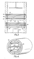
- a laser arrangement includes a cylindrical cathode member 24 which is surrounded by a ceramic envelope tube 25 and includes a plurality of slots 26 which each have a width of a millimetre or so and which are aligned with the longitudinal axis of the tube 25.
- a rod anode member 27 is located along the longitudinal axis of the tube 25.
- Windows (not shown) are included at each end of the tube 25.
- the tube 25 and cathode member 24 contain a gas or vapour at a pressure of a fraction of a torr or so, such that when a suitably high potential difference of a few kilovolts is applied between the anode member 27 and cathode member 24 a plurality of electron beam sheets are produced extensive of the slots 26.
- the electron beam sheets cause excitation of the gas filling, enabling laser action to be achieved.
Landscapes
- Physics & Mathematics (AREA)
- Electromagnetism (AREA)
- High Energy & Nuclear Physics (AREA)
- Engineering & Computer Science (AREA)
- Plasma & Fusion (AREA)
- Optics & Photonics (AREA)
- Lasers (AREA)
- Electron Sources, Ion Sources (AREA)
- Glass Compositions (AREA)
- Percussion Or Vibration Massage (AREA)
- Electrically Driven Valve-Operating Means (AREA)
- Laminated Bodies (AREA)
Applications Claiming Priority (2)
| Application Number | Priority Date | Filing Date | Title |
|---|---|---|---|
| GB8621022A GB2194673B (en) | 1986-08-30 | 1986-08-30 | Apparatus for forming an electron beam sheet |
| GB8621022 | 1986-08-30 |
Publications (2)
| Publication Number | Publication Date |
|---|---|
| EP0259028A2 true EP0259028A2 (de) | 1988-03-09 |
| EP0259028A3 EP0259028A3 (de) | 1989-10-18 |
Family
ID=10603457
Family Applications (1)
| Application Number | Title | Priority Date | Filing Date |
|---|---|---|---|
| EP87307062A Withdrawn EP0259028A3 (de) | 1986-08-30 | 1987-08-10 | Gerät zur Formung eines handförmigen Elektronenstrahls |
Country Status (5)
| Country | Link |
|---|---|
| US (1) | US4839554A (de) |
| EP (1) | EP0259028A3 (de) |
| JP (2) | JPS6394535A (de) |
| AU (1) | AU598579B2 (de) |
| GB (2) | GB2194673B (de) |
Cited By (1)
| Publication number | Priority date | Publication date | Assignee | Title |
|---|---|---|---|---|
| FR2708810A1 (fr) * | 1993-07-29 | 1995-02-10 | Litton Systems Inc | Positionnement d'une cathode dans un interrupteur à décharge dans un gaz. |
Families Citing this family (3)
| Publication number | Priority date | Publication date | Assignee | Title |
|---|---|---|---|---|
| GB2211018B (en) * | 1987-10-10 | 1992-02-19 | English Electric Valve Co Ltd | Laser apparatus |
| DE4218479A1 (de) * | 1992-06-04 | 1993-12-09 | Siemens Ag | Gasentladungsschalter |
| US6229837B1 (en) * | 1998-10-29 | 2001-05-08 | Tokai Research Establishment Of Japan Atomic Energy Research Institute | Metal-vapor pulsed laser |
Family Cites Families (20)
| Publication number | Priority date | Publication date | Assignee | Title |
|---|---|---|---|---|
| DE686245C (de) * | 1934-12-22 | 1940-01-05 | Elin Akt Ges Fuer Elek Sche In | Gas- oder Dampfentladungsgefaess mit indirekt beheizter Gluehkathode |
| GB824762A (en) * | 1955-01-27 | 1959-12-02 | British Thomson Houston Co Ltd | Improvements relating to controllable gas-filled electric discharge devices of the thyratron type |
| US2937301A (en) * | 1956-04-25 | 1960-05-17 | Edgerton Germeshausen & Grier | Electric-discharge device and cathode |
| US3381157A (en) * | 1964-12-10 | 1968-04-30 | United Aircraft Corp | Annular hollow cathode discharge apparatus |
| FR2091869B1 (de) * | 1970-03-02 | 1974-08-09 | Commissariat Energie Atomique | |
| US3864640A (en) * | 1972-11-13 | 1975-02-04 | Willard H Bennett | Concentration and guidance of intense relativistic electron beams |
| US3947781A (en) * | 1975-02-27 | 1976-03-30 | Karl Gerhard Hernqvist | Laser device |
| US4180784A (en) * | 1977-09-19 | 1979-12-25 | The Boeing Company | Frequency modulated electrical discharge laser |
| GB1583493A (en) * | 1978-03-08 | 1981-01-28 | English Electric Valve Co Ltd | Thyratrons |
| US4308507A (en) * | 1979-12-11 | 1981-12-29 | The United States Of America As Represented By The United States Department Of Energy | Electron beam switched discharge for rapidly pulsed lasers |
| GB2065962B (en) * | 1979-12-21 | 1983-11-02 | English Electric Valve Co Ltd | Thyratrosns |
| GB2125613B (en) * | 1982-08-03 | 1986-01-08 | English Electric Valve Co Ltd | Improvements in thyratrons |
| DE3343488A1 (de) * | 1983-12-01 | 1985-06-13 | W.C. Heraeus Gmbh, 6450 Hanau | Gaslaser |
| GB2153140B (en) * | 1983-12-20 | 1988-08-03 | English Electric Valve Co Ltd | Apparatus for forming electron beams |
| DE3485897T2 (de) * | 1983-12-20 | 1993-01-07 | Eev Ltd | Elektronenstrahlerzeuger. |
| US4596945A (en) * | 1984-05-14 | 1986-06-24 | Hughes Aircraft Company | Modulator switch with low voltage control |
| US4545056A (en) * | 1984-06-19 | 1985-10-01 | The United States Of America As Represented By The Secretary Of The Army | Depressed collector/ribbon electron beam analyzer for a diffraction radiation generator |
| GB2169131B (en) * | 1984-12-22 | 1988-11-09 | English Electric Valve Co Ltd | Gas discharge devices |
| US4703226A (en) * | 1984-12-22 | 1987-10-27 | English Electric Valve Company Limited | Thyratron having anode and multiple grids |
| GB8608610D0 (en) * | 1986-04-09 | 1986-05-14 | English Electric Valve Co Ltd | Laser apparatus |
-
1986
- 1986-08-30 GB GB8621022A patent/GB2194673B/en not_active Expired - Lifetime
-
1987
- 1987-07-29 GB GB8718005A patent/GB2194674B/en not_active Expired - Lifetime
- 1987-08-10 EP EP87307062A patent/EP0259028A3/de not_active Withdrawn
- 1987-08-26 JP JP62212650A patent/JPS6394535A/ja active Pending
- 1987-08-28 AU AU77660/87A patent/AU598579B2/en not_active Ceased
- 1987-08-28 US US07/090,454 patent/US4839554A/en not_active Expired - Fee Related
- 1987-08-31 JP JP62217752A patent/JPS63133432A/ja active Pending
Cited By (1)
| Publication number | Priority date | Publication date | Assignee | Title |
|---|---|---|---|---|
| FR2708810A1 (fr) * | 1993-07-29 | 1995-02-10 | Litton Systems Inc | Positionnement d'une cathode dans un interrupteur à décharge dans un gaz. |
Also Published As
| Publication number | Publication date |
|---|---|
| GB2194674A (en) | 1988-03-09 |
| GB2194674B (en) | 1990-07-11 |
| GB8718005D0 (en) | 1987-09-03 |
| GB8621022D0 (en) | 1986-10-08 |
| GB2194673B (en) | 1990-10-24 |
| AU7766087A (en) | 1988-03-03 |
| JPS63133432A (ja) | 1988-06-06 |
| GB2194673A (en) | 1988-03-09 |
| EP0259028A3 (de) | 1989-10-18 |
| AU598579B2 (en) | 1990-06-28 |
| US4839554A (en) | 1989-06-13 |
| JPS6394535A (ja) | 1988-04-25 |
Similar Documents
| Publication | Publication Date | Title |
|---|---|---|
| Schoenbach et al. | Microhollow cathode discharges | |
| US4335465A (en) | Method of producing an accellerating electrons and ions under application of voltage and arrangements connected therewith | |
| US3831052A (en) | Hollow cathode gas discharge device | |
| US4061944A (en) | Electron beam window structure for broad area electron beam generators | |
| EP0185045B1 (de) | Draht-ionenplasma-elektronenkanone mit hilfsgitter | |
| EP0428527A1 (de) | Plasma elektronengewehr fur ionen aus einer entfernte quelle. | |
| WO1982004350A1 (en) | Filament dispenser cathode | |
| US3381157A (en) | Annular hollow cathode discharge apparatus | |
| US3999072A (en) | Beam-plasma type ion source | |
| US4839554A (en) | Apparatus for forming an electron beam sheet | |
| KR100216657B1 (ko) | 마그네트론 | |
| US3518433A (en) | Methods and apparatus for generating flash x-rays employing a three electrode field emission x-ray tube | |
| US3862449A (en) | Ion sleeve for arc lamp electrode | |
| US5021708A (en) | Cathode for emission of electrons and electron tube with a cathode of this type | |
| US4163172A (en) | Sliding spark source cold cathode electron gun and method | |
| US4939425A (en) | Four-electrode ion source | |
| US4087720A (en) | Multi-beam, multi-aperture ion sources of the beam-plasma type | |
| EP0101043A2 (de) | Elektronenstrahlerzeugungssystem mit Plasmakathode | |
| US5072148A (en) | Dispenser cathode with emitting surface parallel to ion flow and use in thyratrons | |
| US4123684A (en) | Thyratrons | |
| US4879490A (en) | Gas discharge devices wherein electrons are injected into a high field region | |
| SU692430A1 (ru) | Электронна газоразр дна пушка | |
| JPS6321879Y2 (de) | ||
| GB2169131A (en) | Gas discharge devices | |
| SU1367063A1 (ru) | Рел тивистский СВЧ-генератор |
Legal Events
| Date | Code | Title | Description |
|---|---|---|---|
| PUAI | Public reference made under article 153(3) epc to a published international application that has entered the european phase |
Free format text: ORIGINAL CODE: 0009012 |
|
| AK | Designated contracting states |
Kind code of ref document: A2 Designated state(s): DE FR IT NL |
|
| PUAL | Search report despatched |
Free format text: ORIGINAL CODE: 0009013 |
|
| AK | Designated contracting states |
Kind code of ref document: A3 Designated state(s): DE FR IT NL |
|
| 17P | Request for examination filed |
Effective date: 19900208 |
|
| 17Q | First examination report despatched |
Effective date: 19920629 |
|
| STAA | Information on the status of an ep patent application or granted ep patent |
Free format text: STATUS: THE APPLICATION IS DEEMED TO BE WITHDRAWN |
|
| 18D | Application deemed to be withdrawn |
Effective date: 19940301 |
|
| RIN1 | Information on inventor provided before grant (corrected) |
Inventor name: MAITLAND, ARTHUR Inventor name: WEATHERUP, CLIFFORD ROBERT Inventor name: STRUDWICK, IAN ARTHUR |