EP0258570A2 - Device for moving a carriage or the like in a direction with an essentially constant speed and its return with a unequal speed - Google Patents
Device for moving a carriage or the like in a direction with an essentially constant speed and its return with a unequal speed Download PDFInfo
- Publication number
- EP0258570A2 EP0258570A2 EP87109624A EP87109624A EP0258570A2 EP 0258570 A2 EP0258570 A2 EP 0258570A2 EP 87109624 A EP87109624 A EP 87109624A EP 87109624 A EP87109624 A EP 87109624A EP 0258570 A2 EP0258570 A2 EP 0258570A2
- Authority
- EP
- European Patent Office
- Prior art keywords
- lever
- roller
- rollers
- carriage
- belt
- Prior art date
- Legal status (The legal status is an assumption and is not a legal conclusion. Google has not performed a legal analysis and makes no representation as to the accuracy of the status listed.)
- Granted
Links
Images


Classifications
-
- B—PERFORMING OPERATIONS; TRANSPORTING
- B29—WORKING OF PLASTICS; WORKING OF SUBSTANCES IN A PLASTIC STATE IN GENERAL
- B29C—SHAPING OR JOINING OF PLASTICS; SHAPING OF MATERIAL IN A PLASTIC STATE, NOT OTHERWISE PROVIDED FOR; AFTER-TREATMENT OF THE SHAPED PRODUCTS, e.g. REPAIRING
- B29C66/00—General aspects of processes or apparatus for joining preformed parts
- B29C66/80—General aspects of machine operations or constructions and parts thereof
- B29C66/83—General aspects of machine operations or constructions and parts thereof characterised by the movement of the joining or pressing tools
- B29C66/834—General aspects of machine operations or constructions and parts thereof characterised by the movement of the joining or pressing tools moving with the parts to be joined
- B29C66/8351—Jaws mounted on rollers, cylinders, drums, bands, belts or chains; Flying jaws
- B29C66/83541—Jaws mounted on rollers, cylinders, drums, bands, belts or chains; Flying jaws flying jaws, e.g. jaws mounted on crank mechanisms or following a hand over hand movement
- B29C66/83543—Jaws mounted on rollers, cylinders, drums, bands, belts or chains; Flying jaws flying jaws, e.g. jaws mounted on crank mechanisms or following a hand over hand movement cooperating flying jaws
-
- B—PERFORMING OPERATIONS; TRANSPORTING
- B29—WORKING OF PLASTICS; WORKING OF SUBSTANCES IN A PLASTIC STATE IN GENERAL
- B29C—SHAPING OR JOINING OF PLASTICS; SHAPING OF MATERIAL IN A PLASTIC STATE, NOT OTHERWISE PROVIDED FOR; AFTER-TREATMENT OF THE SHAPED PRODUCTS, e.g. REPAIRING
- B29C65/00—Joining or sealing of preformed parts, e.g. welding of plastics materials; Apparatus therefor
- B29C65/02—Joining or sealing of preformed parts, e.g. welding of plastics materials; Apparatus therefor by heating, with or without pressure
- B29C65/18—Joining or sealing of preformed parts, e.g. welding of plastics materials; Apparatus therefor by heating, with or without pressure using heated tools
-
- B—PERFORMING OPERATIONS; TRANSPORTING
- B29—WORKING OF PLASTICS; WORKING OF SUBSTANCES IN A PLASTIC STATE IN GENERAL
- B29C—SHAPING OR JOINING OF PLASTICS; SHAPING OF MATERIAL IN A PLASTIC STATE, NOT OTHERWISE PROVIDED FOR; AFTER-TREATMENT OF THE SHAPED PRODUCTS, e.g. REPAIRING
- B29C66/00—General aspects of processes or apparatus for joining preformed parts
- B29C66/40—General aspects of joining substantially flat articles, e.g. plates, sheets or web-like materials; Making flat seams in tubular or hollow articles; Joining single elements to substantially flat surfaces
- B29C66/41—Joining substantially flat articles ; Making flat seams in tubular or hollow articles
- B29C66/43—Joining a relatively small portion of the surface of said articles
- B29C66/431—Joining the articles to themselves
- B29C66/4312—Joining the articles to themselves for making flat seams in tubular or hollow articles, e.g. transversal seams
-
- F—MECHANICAL ENGINEERING; LIGHTING; HEATING; WEAPONS; BLASTING
- F16—ENGINEERING ELEMENTS AND UNITS; GENERAL MEASURES FOR PRODUCING AND MAINTAINING EFFECTIVE FUNCTIONING OF MACHINES OR INSTALLATIONS; THERMAL INSULATION IN GENERAL
- F16H—GEARING
- F16H21/00—Gearings comprising primarily only links or levers, with or without slides
- F16H21/10—Gearings comprising primarily only links or levers, with or without slides all movement being in, or parallel to, a single plane
- F16H21/16—Gearings comprising primarily only links or levers, with or without slides all movement being in, or parallel to, a single plane for interconverting rotary motion and reciprocating motion
- F16H21/18—Crank gearings; Eccentric gearings
- F16H21/36—Crank gearings; Eccentric gearings without swinging connecting-rod, e.g. with epicyclic parallel motion, slot-and-crank motion
-
- B—PERFORMING OPERATIONS; TRANSPORTING
- B29—WORKING OF PLASTICS; WORKING OF SUBSTANCES IN A PLASTIC STATE IN GENERAL
- B29C—SHAPING OR JOINING OF PLASTICS; SHAPING OF MATERIAL IN A PLASTIC STATE, NOT OTHERWISE PROVIDED FOR; AFTER-TREATMENT OF THE SHAPED PRODUCTS, e.g. REPAIRING
- B29C66/00—General aspects of processes or apparatus for joining preformed parts
- B29C66/01—General aspects dealing with the joint area or with the area to be joined
- B29C66/05—Particular design of joint configurations
- B29C66/10—Particular design of joint configurations particular design of the joint cross-sections
- B29C66/11—Joint cross-sections comprising a single joint-segment, i.e. one of the parts to be joined comprising a single joint-segment in the joint cross-section
- B29C66/112—Single lapped joints
- B29C66/1122—Single lap to lap joints, i.e. overlap joints
Definitions
- the invention relates to a device for moving a carriage or the like in one direction at substantially the same speed and for returning it at a non-uniform speed, preferably for the intermittent preference of a film web relative to a welding device fixed to the frame or for the intermittent speed-equal advancement of a welding device relative to one moving film web, with a lever that can be swiveled back and forth by a drive, which, via a first link guide running in the longitudinal direction thereof, and a sliding block or a roller in a plane parallel to the pivoting plane of the lever Guides movable carriage gives the drive movement, the holder of the sliding block or the bearing of the roller are slidably guided on a line which is the basis of an isosceles triangle, the legs of which are defined by the lever pivoted into its end positions.
- the object of the invention is therefore to provide a device of the type specified at the outset, which has a more compact and thus space-saving design.
- this object is achieved in a device of the generic type in that the drive of the lever consists of a crank rotating in a plane parallel to the pivoting plane of the lever with a driven crankshaft journal, the crankpin of which carries a sliding block or a roller which in a second link guide of the Lever runs, which is located on the side opposite the first link guide.
- the lever thus covers the crank serving to drive it, so that a compact, space-saving design is possible.
- This first embodiment of the device according to the invention makes it possible to carry out processing on a device continuous web, in particular tubular film web, to be provided, for example, for the production of sacks with transverse weld seams or also with punched-outs.
- a device continuous web in particular tubular film web
- webs preferably tubular webs, from which sections, for example bags provided with bottom and / or top seams, are separated and conveyed individually, in shingles one above the other or in stack form.
- rollers or rollers are mounted in the end regions of the slide transversely to its direction of movement, via which an endless belt or an endless belt runs, the upper run loop-like deflecting rollers or - rolls wraps around and the lower run in loop form runs over preferred rollers for the film web, and that the film web from the preferred rollers over the rear roller in the film feed direction and the first of the upper run of the belt or Belt intermittently driven frame-fixed deflection roller runs.
- the rollers or rollers mounted in the carriage and the frame-fixed rollers or rollers are driven or coupled by the endless belt that wraps around them, so that they are in drive connection with the preferred rollers for the incoming film web, without all rollers and / or rollers from the Foil sheet itself are wrapped.
- the film web which in this embodiment only runs over the rear roller of the carriage in the film feed direction and the first frame-fixed deflection roller driven intermittently by the upper run of the belt or belt, can therefore pass behind this deflection roller continued in any form or separated and stored in sections.
- the first deflecting roller fixed to the frame which is driven intermittently by the upper run of the belt or belt, is a roller of a second pair of preferred rollers for the film web.
- a depositing table or a depositing conveyor belt can be provided behind this roller or this second pair of preferred rollers, a cross-welding separating or cross-cutting device which separates sections or bags from the web or tubular film web can be arranged between the two.
- crank pin is fastened in a holder which on a radial guide of the crank is longitudinally displaceable to this and that the holder is provided on its side opposite the crank pin with a pin which carries a sliding block or a roller which runs in a closed frame-fixed curve guide enclosing the crankshaft pin with the desired characteristic.
- the guides of the slide run parallel to the base of the isosceles triangle and that the slide is provided with a guide perpendicular to these guides, in which the carrier of the in the first guide of the lever-guided roller is guided adjustable by adjusting means.
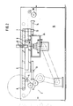
- a supply roll 1 is mounted in a stand, from which a film tube web 2, for example to be processed into bags or sacks, is continuously drawn off by the feed rollers 3.
- the film tubular web 2 runs over a frame-fixed deflection roller 4 to two rollers 6 and 7 mounted at a distance from one another in a carriage 5.
- a frame-fixed sealing device 8 of a conventional type is provided.
- the film tubular web provided with sealing seams then runs over a deflection roller 9 fixed to the frame and a feed roller 10 to a buffer store consisting of a pendulum roller 11 and from there to the winding device 12, by means of which the tubular film web provided with weld seams is wound up into a supply roll.
- the carriage 5 is provided with guide brackets 13 which grip guide rods 14 fixed to the frame and are guided thereon.
- the two guide rods 14 are firmly connected to the machine frame 15 in the region of their ends, so that the slide 5 can be pushed back and forth on the guide rods 14 in the direction of arrow A.
- it has a guide groove 16 in which an adjusting nut 17 is guided, which can be displaced via a threaded spindle rod in the groove 16 for the purpose of format adjustment.
- a pin 19 is fixedly connected to the adjusting nut 17 and carries a guide roller 20 at its end facing away from the adjusting nut 17.
- This guide roller 20 is guided in a guide track 21 which is provided in the rocker 22 consisting of a lever.
- the rocker 22 is pivotally mounted about the axis 23 in the gear housing 24, which is connected to the frame.
- the rocker 22 is next to the Guide track 21 provided with a second guide track 25 running parallel to this.
- a roller 26 is guided, which is placed on one end of the crank pin 27.
- the crank pin 27 is held by a sliding block 28 which is slidably mounted in the crank arm 30 on guide rods 29.
- the crank arm 30 is fastened on the crankshaft journal 31.
- the degree of displacement of the sliding block 28 on the guide rods 29 with each revolution of the crankshaft journal 31 is determined by the configuration of the cam groove 32, in which a roller 33 is guided, which is placed on the end of the crankpin 27 opposite the roller 26.
- the cam groove 32 is machined into the hub 34, which is firmly connected to the housing 24.
- the design of the guide groove 32 ensures that a constant speed is achieved in the manner shown in the diagrams according to FIGS. 7 and 8 over a certain path, so that the deflecting rollers 6, 7 of the carriage 5 during the sealing time with such Speed are shifted so that there is no relative movement between the continuously drawn hose or half-hose web 2 and the sealing device 8.
- the intermittent standstill of the tubular film web 2 during the sealing times is achieved by correspondingly moving the slide 5, the end position of the slide being shown in FIG. 6 by the rollers 6 shown in broken lines.
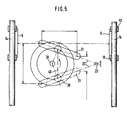
- Fig. 5 the slide 5 is shown schematically on the guide rods 14. Furthermore, the rocker arm 22, which can be pivoted about the axis 23, has dash-dotted lines and the guide groove 21 provided on its upper side has been hinted at.
- the roller 20 is guided in the guide groove 21. Since the roller 20 is adjustable via its holder 17 in the groove 16 of the slide 15, the slide stroke can be adjusted from the maximum stroke length shown to the indicated minimum stroke length by the adjustment. Since the roller 20 is held in its respective setting relative to the slide, it is guided on lines parallel to the guides 14, of which a line 40 is indicated by dashed lines in FIG. 5. As can be seen from FIG. 5, line 40 is the basis of an isosceles triangle, the legs of which are defined by the rocker arm 22 pivoted into its end positions.
- FIG. 9 shows a device in which bags provided with bottom weld seams from the tubular film web 42 are welded and placed on a stacking belt.
- the device has two side frames, of which only the rear side frame 41 is shown for the sake of clarity.
- a pair of preferred rollers 42 is mounted, via which the tubular web 43 is continuously advanced.
- a deflection roller 44 and a pair of preferred rollers 45 are mounted in the side frame 41.
- two parallel guide rods 45 are provided, which are connected via crossbars 47 to the side frame (not shown) and to the side frame 41.
- a slide 48 is slidably placed on the guide rods 46 and carries two deflection rollers 49 and 50.
- the carriage 48 is traced in the manner described with reference to FIGS. 1 to 8. From the drawing it can be seen that the pair of preferred rollers 42, the deflection roller 49, the lower deflection roller of the pair of rollers 45, the deflection roller 44 and the deflection roller 50 are wrapped in an endless belt 51.
- the hose web 43 continuously advanced by the pair of preferred rollers 42 only wraps around the deflection roller 49. It then follows then discontinuously advanced by the pair of preferred rollers 45.
- Via a device known per se, denoted by 52, 45 individual hose sections are then separated from the web 43 and provided, for example, with a bottom seam, in time with the pair of preferred rollers. The individual separated hose sections can then, for example, be placed on a scale-forming conveyor belt 53.
Landscapes
- Engineering & Computer Science (AREA)
- Mechanical Engineering (AREA)
- General Engineering & Computer Science (AREA)
- Making Paper Articles (AREA)
- Containers And Plastic Fillers For Packaging (AREA)
- Lining Or Joining Of Plastics Or The Like (AREA)
- Transmission Devices (AREA)
Abstract
Eine Vorrichtung dient zum Verfahren eines Schlittens in einer Richtung mit im wesentlichen gleicher Geschwindigkeit und zu dessen Zurückführen mit ungleichförmiger Geschwindigkeit zum intermittierenden Vorzug einer mit konstanter Geschwindigkeit zugeführter Folienbahn relativ zu einer gestellfesten Schweißeinrichtung. Die Vorrichtung besitzt einen durch einen Antrieb hin- und herverschwenkbaren Hebel, der über eine in dessen Längsrichtung in diesem verlaufende erste Kulissenführung und einen Gleitstein oder eine Rolle dem in einer zur Schwenkebene des Hebels parallelen Ebene in Führungen verfahrbaren Schlitten die Antriebsbewegung erteilt. Die Halterung des Gleitsteins oder das Lager der Rolle sind auf einer Linie verschieblich geführt, die die Basis eines gleichschenkeligen Dreiecks ist, dessen Schenkel durch den in seine Endlagen verschwenkten Hebel definiert sind. Um dieser Vorrichtung eine gedrungenere und damit platzsparende Bauweise zur verleihen, besteht der Antrieb des Hebels (22) aus einer in einer zu der Schwenkebene des Hebels (22) parallelen Ebene umlaufenden Kurbel mit angetriebenem Kurbelwellenzapfen (31), deren Kurbelzapfen einen Gleitstein oder eine Rolle trägt, die in einer zweiten Kulissenführung des Hebels (22) läuft, die sich auf dessen der ersten Kulissenführung (21) gegenüberliegenden Seite befindet (Fig. 5). A device is used to move a carriage in one direction at substantially the same speed and to return it at a non-uniform speed for the intermittent preference of a film web fed at a constant speed relative to a welding device fixed to the frame. The device has a lever which can be pivoted back and forth by a drive and which, via a first link guide running in the longitudinal direction thereof and a sliding block or a roller, gives the drive movement to the slide which is movable in guides in a plane parallel to the pivoting plane of the lever. The holder of the sliding block or the bearing of the roller are slidably guided on a line which is the base of an isosceles triangle, the legs of which are defined by the lever pivoted into its end positions. In order to give this device a more compact and therefore space-saving design, the drive of the lever (22) consists of a crank rotating in a plane parallel to the pivoting plane of the lever (22) with a driven crankshaft journal (31), the crankpin of which is a sliding block or a roller carries, which runs in a second link guide of the lever (22), which is located on the side opposite the first link guide (21) (Fig. 5).
Description
Die Erfindung betrifft eine Vorrichtung zum Verfahren eines Schlittens o. dgl. in einer Richtung mit im wesentlichen gleicher Geschwindigkeit und zu dessen Zurückführen mit ungleichförmiger Geschwindigkeit, vorzugsweise zum intermittierenden Vorzug einer Folienbahn relativ zu einer gestellfesten Schweißeinrichtung oder zum taktweisen geschwindigkeitsgleichen Vorschub einer Schweißeinrichtung relativ zu einer bewegten Folienbahn, mit einem durch einen Antrieb hin- und herverschwenkbaren Hebel, der über eine in dessen Längsrichtung in diesem verlaufende erste Kulissenführung und einen Gleitstein oder eine Rolle dem in einer zu der Schwenkebene des Hebels parallelen Ebene in Führungen verfahrbaren Schlitten die Antriebsbewegung erteilt, wobei die Halterung des Gleitsteins oder das Lager der Rolle auf einer Linie verschieblich geführt sind, die die Basis eines gleichschenkeligen Dreiecks ist, dessen Schenkel durch den in seine Endlagen verschwenkten Hebel definiert sind.The invention relates to a device for moving a carriage or the like in one direction at substantially the same speed and for returning it at a non-uniform speed, preferably for the intermittent preference of a film web relative to a welding device fixed to the frame or for the intermittent speed-equal advancement of a welding device relative to one moving film web, with a lever that can be swiveled back and forth by a drive, which, via a first link guide running in the longitudinal direction thereof, and a sliding block or a roller in a plane parallel to the pivoting plane of the lever Guides movable carriage gives the drive movement, the holder of the sliding block or the bearing of the roller are slidably guided on a line which is the basis of an isosceles triangle, the legs of which are defined by the lever pivoted into its end positions.
Zwei Vorrichtungen dieser Art sind aus der DE-PS 32 34 227 bekannt. Die sogenannten Kurvengleichlaufgetriebe dieser Vorrichtungen haben sich sehr bewährt, diese weisen allerdings den Nachteil auf, daß sie einen großen Einbauraum benötigen. Dies ist darauf zurückzuführen, daß die den Schlitten antreibenden, hin- und herverschwenkbaren Hebel als zweiarmige Hebel ausgebildet sind, von denen der dem Antrieb dienende Hebelarm mit Kurvenrollen versehen ist, die eine Stegkurve einer rotierenden Kurvenscheibe einfassen, von der die Antriebsbewegung abgeleitet ist.Two devices of this type are known from DE-PS 32 34 227. The so-called cornering gears of these devices have proven very successful, but they have the disadvantage that they require a large installation space. This can be attributed to the fact that the slide driving, swiveling levers are designed as two-armed levers, of which the lever arm serving for the drive is provided with cam rollers which enclose a web curve of a rotating cam disc from which the drive movement is derived.
Aufgabe der Erfindung ist es daher, eine Vorrichtung der eingangs angegebenen Art zu schaffen, die eine gedrungenere und damit platzsparende Bauweise aufweist.The object of the invention is therefore to provide a device of the type specified at the outset, which has a more compact and thus space-saving design.
Erfindungsgemäß wird diese Aufgabe bei einer Vorrichtung der gattungsgemäßen Art dadurch gelöst, daß der Antrieb des Hebels aus einer in einer zur Schwenkebene des Hebels parallelen Ebene umlaufenden Kurbel mit angetriebenem Kurbelwellenzapfen besteht, deren Kurbelzapfen einen Gleitstein oder eine Rolle trägt, die in einer zweiten Kulissenführung des Hebels läuft, die sich auf dessen der ersten Kulissenführung gegenüberliegenden Seite befindet. Bei der erfindungsgemäßen Vorrichtung überdeckt also der Hebel die dessen Antrieb dienende Kurbel, so daß eine gedrungene platzsparende Bauweise möglich ist.According to the invention, this object is achieved in a device of the generic type in that the drive of the lever consists of a crank rotating in a plane parallel to the pivoting plane of the lever with a driven crankshaft journal, the crankpin of which carries a sliding block or a roller which in a second link guide of the Lever runs, which is located on the side opposite the first link guide. In the device according to the invention, the lever thus covers the crank serving to drive it, so that a compact, space-saving design is possible.
Diese erste Ausführungsform der erfindungsgemäßen Vorrichtung ermöglicht es, Bearbeitungen an einer durch die Vorrichtung durchlaufenden Bahn, insbesondere Schlauchfolienbahn, vorzunehmen, diese also beispielsweise zur Herstellung von Säcken mit Querschweißnähten oder aber auch mit Ausstanzungen zu versehen. Es besteht aber auch das Bedürfnis, die erfindungsgemäße Vorrichtung für Bahnen, vorzugsweise Schlauchbahnen, zu verwenden, von denen Abschnitte, beispielsweise mit Boden- und/oder Kopfnähten versehene Beutel abgetrennt und einzeln, geschuppt übereinanderliegend oder in Stapelform abgefördert werden.This first embodiment of the device according to the invention makes it possible to carry out processing on a device continuous web, in particular tubular film web, to be provided, for example, for the production of sacks with transverse weld seams or also with punched-outs. However, there is also a need to use the device according to the invention for webs, preferably tubular webs, from which sections, for example bags provided with bottom and / or top seams, are separated and conveyed individually, in shingles one above the other or in stack form.
In weiterer Ausgestaltung ist daher bei einer erfindungsgemäßen Vorrichtung zum intermittierenden Vorzug einer mit konstanter Geschwindigkeit zugeführten Folienbahn relativ zu einer gestellfesten Quertrenn- oder Quertrennschweißeinrichtung vorgesehen, daß in den Endbereichen des Schlittens quer zu dessen Verschieberichtung Walzen oder Rollen gelagert sind, über die ein endloses Band oder ein endloser Riemen läuft, dessen Obertrum schlaufenartig gestellfeste Umlenkwalzen oder - rollen umschlingt und dessen Untertrum in Schlaufenform über Vorzugswalzen für die Folienbahn läuft, und daß die Folienbahn von den Vorzugswalzen über die in Folienzuführungsrichtung hintere Walze des Schlittens und die erste von dem Obertrum des Bandes oder Riemens intermittierend angetriebene gestellfeste Umlenkwalze läuft.In a further embodiment, therefore, in a device according to the invention for the intermittent preference of a film web fed at a constant speed relative to a cross-cut or cross-cut welding device fixed to the frame, rollers or rollers are mounted in the end regions of the slide transversely to its direction of movement, via which an endless belt or an endless belt runs, the upper run loop-like deflecting rollers or - rolls wraps around and the lower run in loop form runs over preferred rollers for the film web, and that the film web from the preferred rollers over the rear roller in the film feed direction and the first of the upper run of the belt or Belt intermittently driven frame-fixed deflection roller runs.
Bei dieser Ausgestaltung sind die in dem Schlitten gelagerten sowie die gestellfesten Walzen oder Rollen durch den diese umschlingenden enlosen Riemen angetrieben bzw. gekuppelt, so daß diese mit den Vorzugswalzen für die einlaufende Folienbahn in Antriebsverbindung stehen, ohne daß alle Walzen und/oder Rollen von der Folienbahn selbst umschlungen sind. Die Folienbahn, die bei dieser Ausführungsform nur über die in Folienzuführungsrichtung hintere Walze des Schlittens und die erste von dem Obertrum des Bandes oder Riemens intermittierend angetriebene gestellfeste Umlenkwalze läuft, kann also hinter dieser Umlenkwalze in beliebiger Form weitergeführt oder abschnittweise abgetrennt und abgelegt werden.In this embodiment, the rollers or rollers mounted in the carriage and the frame-fixed rollers or rollers are driven or coupled by the endless belt that wraps around them, so that they are in drive connection with the preferred rollers for the incoming film web, without all rollers and / or rollers from the Foil sheet itself are wrapped. The film web, which in this embodiment only runs over the rear roller of the carriage in the film feed direction and the first frame-fixed deflection roller driven intermittently by the upper run of the belt or belt, can therefore pass behind this deflection roller continued in any form or separated and stored in sections.
Zweckmäßigerweise ist die erste von dem Obertrum des Bandes oder Riemens intermittierend angetriebene gestellfeste Unlenkwalze eine Walze eines zweiten Vorzugswalzenpaares für die Folienbahn. Hinter dieser Walze bzw. diesem zweiten Vorzugswalzenpaar kann ein Ablagetisch oder ein Ablageförderband vorgesehen sein, wobei zwischen beiden eine Querschweißtrenn- oder Querschneideeinrichtung angeordnet sein kann, die von der Bahn oder Schlauchfolienbahn Abschnitte oder Beutel abtrennt.Advantageously, the first deflecting roller fixed to the frame, which is driven intermittently by the upper run of the belt or belt, is a roller of a second pair of preferred rollers for the film web. A depositing table or a depositing conveyor belt can be provided behind this roller or this second pair of preferred rollers, a cross-welding separating or cross-cutting device which separates sections or bags from the web or tubular film web can be arranged between the two.
Um dem Kurbelantrieb eine Antriebsbewegung zu erteilen, die über eine möglichst lange Strecke oder möglichst lange Zeit einen Gleichlauf der Schweißwerkzeuge mit der Folienbahn oder einen Stillstand der Folienbahn ermöglicht, ist in weiterer Ausgestaltung der Erfindung vorgesehen, daß der Kurbelzapfen in einer Halterung befestigt ist, die auf einer radialen Führung der Kurbel längsverschieblich zu dieser geführt ist und daß die Halterung auf ihrer dem Kurbelzapfen gegenüberliegenden Seite mit einem Zapfen versehen ist, der einen Gleitstein oder eine Rolle trägt, die in einer den Kurbelwellenzapfen einfassenden geschlossenen gestellfesten Kurvenführung mit der gewünschten Charakteristik läuft.In order to give the crank drive a drive movement, which allows the welding tools to run in synch with the film web or a standstill of the film web over the longest possible distance or as long as possible, it is provided in a further embodiment of the invention that the crank pin is fastened in a holder which on a radial guide of the crank is longitudinally displaceable to this and that the holder is provided on its side opposite the crank pin with a pin which carries a sliding block or a roller which runs in a closed frame-fixed curve guide enclosing the crankshaft pin with the desired characteristic.
Um weiterhin eine einfache Formatumstellung zu ermöglichen, ist in weiterer Ausgestaltung der Erfindung vorgesehen, daß die Führungen des Schlittens parallel zu der Basis des gleichschenkeligen Dreiecks verlaufen und daß der Schlitten mit einer zu diesen Führungen rechtwinkeligen Führung versehen ist, in der der Träger der in der ersten Kulissenführung des Hebels geführten Rolle durch Stellmittel verstellbar geführt ist.In order to enable a simple format changeover, it is provided in a further embodiment of the invention that the guides of the slide run parallel to the base of the isosceles triangle and that the slide is provided with a guide perpendicular to these guides, in which the carrier of the in the first guide of the lever-guided roller is guided adjustable by adjusting means.
Ausführungsbeispiele der Erfindung werden nachstehend anhand der Zeichnung näher erläutert. In dieser zeigt
- Fig. 1 eine Siegelmaschine in Seitenansicht,
- Fig. 2 den Schlitten mit Schlittenantrieb der Siegelmaschine nach Fig. 1 in vergrößerter Darstellung,
- Fig. 3 einen Schnitt durch das Kurvengleichlaufgetriebe des Schlittenantriebs längs der Linie III - III in Fig. 2,
- Fig. 4 einen Schnitt durch das Kurvengleichlaufgetriebe längs der Linie IV - IV in Fig. 3,
- Fig. 5 eine schematische Draufsicht auf das Kurvengleichlaufgetriebe zur Verdeutlichung der Formatveränderung,
- Fig. 6 eine vergrößerte Darstellung des in Fig. 2 mit strichpunktierter Linie eingekreisten Bereiches,
- Fig. 7 ein Weg-Zeit-Diagramm des Kurvengleichlaufgetriebes,
- Fig. 8 ein Geschweindigkeitsdiagramm des Kurvengleichlaufgetriebes und
- Fig. 9 eine zweite Ausführungsform einer Siegelmaschine zur Herstellung von mit Bodenschweißnähten versehenen Beuteln.
- 1 is a side view of a sealing machine,
- 2 shows the slide with slide drive of the sealing machine according to FIG. 1 in an enlarged view,
- 3 shows a section through the synchronous gear mechanism of the slide drive along the line III-III in FIG. 2,
- 4 shows a section through the cornering gear along the line IV-IV in FIG. 3,
- 5 is a schematic plan view of the synchronous gear mechanism to illustrate the change in format,
- 6 is an enlarged view of the area encircled in FIG. 2 with a dash-dotted line,
- 7 is a path-time diagram of the cornering gear,
- Fig. 8 is a speed diagram of the cornering gear and
- 9 shows a second embodiment of a sealing machine for producing bags provided with bottom weld seams.
Bei der in Fig. 1 dargestellten Siegelmaschine ist in einem Ständer eine Vorratsrolle 1 gelagert, von der durch die Vorzugswalzen 3 kontinuierlich eine beispielsweise zu Beuteln oder Säcken zu verarbeitende Folienschlauchbahn 2 abgezogen wird. Von den Vorzugswalzen 3 läuft die Folienschlauchbahn 2 über eine gestellfeste Umlenkrolle 4 zu zwei mit Abstand zueinander in einem Schlitten 5 gelagerten Walzen 6 und 7. Zwischen diesen Walzen 6 und 7 ist eine gestellfeste Siegeleinrichtung 8 üblicher Bauart vorgesehen. Die mit Siegelnähten versehene Folienschlauchbahn läuft dann über eine gestellfeste Umlenkrolle 9 und eine Vorzugswalze 10 zu einem aus einer Pendelwalze 11 bestehenden Zwischenspeicher und von diesem zu der Aufwickelvorrichtung 12, durch die die mit Schweißnähten versehene Schlauchfolienbahn zu einer Vorratsrolle aufgewickelt wird.In the sealing machine shown in FIG. 1, a
Der Schlitten 5 ist mit Führungskonsolen 13 versehen, die gestellfeste Führungsstangen 14 umgreifen und auf diesen geführt sind. Die beiden Führungsstangen 14 sind im Bereich ihrer Enden mit dem Maschinengestell 15 fest verbunden, so daß der Schlitten 5 in Pfeilrichtung A auf den Führungsstangen 14 hin- und herverschoben werden kann. Um hierzu dem Schlitten die erforderliche Antriebsbewegung zu erteilen, weist dieser eine Führungsnut 16 auf, in der eine Stellmutter 17 geführt ist, welche über eine mit einem Gewinde versehene Spindelstange in der Nut 16 zum Zwecke der Formatverstellung verschoben werden kann. Mit der Stellmutter 17 ist ein Zapfen 19 fest verbunden, der an seinem der Stellmutter 17 abgewandten Ende eine Führungsrolle 20 trägt. Diese Führungsrolle 20 ist in einer Führungsbahn 21 geführt, die in der aus einem Hebel bestehenden Schwinge 22 vorgesehen ist. Die Schwinge 22 ist um die Achse 23 schwenkbar im Getriebegehäuse 24 gelagert, das mit dem Gestell verbunden ist.The
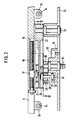
Wie aus Fig. 3 ersichtlich ist, ist die Schwinge 22 neben der Führungsbahn 21 mit einer parallel zu dieser verlaufenden zweiten Führungsbahn 25 versehen. In dieser ist eine Rolle 26 geführt, die auf ein Ende des Kurbelzapfens 27 aufgesetzt ist. Der Kurbelzapfen 27 wird von einem Gleitstein 28 gehalten, der auf Führungsstangen 29 verschiebbar in dem Kurbelarm 30 gelagert ist. Der Kurbelarm 30 ist auf dem Kurbelwellenzapfen 31 befestigt.As can be seen from Fig. 3, the
Das Maß der Verschiebung des Gleitsteins 28 auf den Führungsstangen 29 bei jeder Umdrehung des Kurbelwellenzapfens 31 wird durch die Ausbildung der Kurvennut 32 bestimmt, in der eine Rolle 33 geführt ist, die auf das der Rolle 26 gegenüberliegende Ende des Kurbelzapfens 27 aufgesetzt ist. Die Kurvennut 32 ist in die Nabe 34 eingearbeitet, die fest mit dem Gehäuse 24 verbunden ist.The degree of displacement of the
Durch die Ausgestaltung der Führungsnut 32 wird erreicht, daß in der aus den Diagrammen nach den Fig. 7 und 8 ersichtlichen Weise über einen bestimmten Weg eine konstante Geschwindigkeit erreicht wird, so daß die Umlenkwalzen 6, 7 des Schlittens 5 während der Siegelzeit mit einer solchen Geschwindigkeit verschoben werden, daß keine Relativbewegung zwischen der kontinuierlich abgezogenen Schlauch- oder Halbschlauchbahn 2 und der Siegeleinrichtung 8 entsteht.The design of the
Der intermittierende Stillstand der Schlauchfolienbahn 2 während der Siegelzeiten wird durch entsprechendes Verfahren des Schlittens 5 erreicht, wobei die Endstellung des Schlittens in Fig. 6 durch die gestrichelt eingezeichneten Walzen 6 dargestellt ist.The intermittent standstill of the
In Fig. 5 ist schematisch der auf den Führungsstangen 14 verschiebliche Schlitten 5 dargestellt. Weiterhin ist die um die Achse 23 verschwenkbaren Schwinge 22 mit strichpunktierten Linien und die auf deren Oberseite vorgesehene Führungsnut 21 angedeutet worden. In der Führungsnut 21 ist die Rolle 20 geführt. Da die Rolle 20 über ihre Halterung 17 in der Nut 16 des Schlittens 15 verstellbar ist, läßt sich durch die Verstellung der Schlittenhub von der dargestellten maximalen Hublänge auf die angedeutete minimale Hublänge verstellen. Da die Rolle 20 in ihrer jeweiligen Einstellung relativ zu dem Schlitten festgehalten ist, ist diese auf zu den Führungen 14 parallelen Linien geführt, von denen eine Linie 40 in Fig. 5 gestrichelt angedeutet ist. Wie aus Fig. 5 ersichtlich ist, ist die Linie 40 die Basis eines gleichschenkeligen Dreiecks, dessen Schenkel durch die jeweils in ihre Endlagen verschwenkte Schwinge 22 definiert sind.In Fig. 5 the
Die Fig. 9 zeigt eine Vorrichtung, bei der von der zugeführten Schlauchfolienbahn 42 mit Bodenschweißnähten versehene Beutel abgeschweißt und auf ein Stapelband abgelegt werden. Die Vorrichtung weist zwei Seitengestelle auf, von denen der besseren Ubersichtlichkeit halber nur das hintere Seitengestell 41 dargestellt ist. In diesem ist ein Vorzugswalzenpaar 42 gelagert, über welches die Schlauchbahn 43 kontinuierlich vorgezogen wird. Des weiteren sind in dem Seitengestell 41 eine Umlenkwalze 44 und ein Vorzugswalzenpaar 45 gelagert. Unterhalb des Vorzugswalzenpaares 42 sind zwei parallel zueinander verlaufende Führungsstangen 45 vorgesehen, die über Traversen 47 mit dem nicht dargestellten Seitengestell und mit dem Seitengestell 41 verbunden sind. Auf die Führungsstangen 46 ist gleitend ein Schlitten 48 aufgesetzt, der zwei Umlenkwalzen 49 und 50 trägt. Der Antrib des Schlittens 48 erfolgt in der anhand der Fig. 1 bis 8 beschriebenen Weise. Aus der Zeichnung ist zu erkennen, daß das Vorzugswalzenpaar 42, die Umlenkwalze 49, die untere Umlenkwalze des Walzenpaares 45, die Umlenkwalze 44 und die Umlenkwalze 50 von einem endlosen Band 51 umschlungen sind. Die von dem Vorzugswalzenpaar 42 kontinuierlich vorgezogene Schlauchbahn 43 umschlingt lediglich die Unlenkwalze 49. Sie wird im Anschluß daran von dem Vorzugswalzenpaar 45 diskontinuierlich vorgezogen. Uber eine an sich bekannte, mit 52 bezeichnete Einrichtung werden dann im Takt des Vorzugswalzenpaares 45 einzelne Schlauchabschnitte von der Bahn 43 abgetrennt und beispielsweise mit einer Bodennaht versehen. Die einzelnen abgetrennten Schlauchabschnitte können dann beispielsweise auf ein schuppenbildendes Förderband 53 abgelegt werden.FIG. 9 shows a device in which bags provided with bottom weld seams from the
Zum Zeitpunkt der in Fig. 9 dargestellten Lage des Schlittens 48 wird gerade geschweißt, während sich der Schlitten 48 in Pfeilrichtung A bewegt, und zwar so lange, bis die Umlenkwalze 49 ihre mit gestrichelten Linien dargestellte Lage 49ʹ und die Umlenkwalze 50 ihre mit gestrichelten Linien dargestellte Lage 50ʹ erreicht haben. Durch diese Bewegung des Schlittens 48 wird die kontinuierlich zugeführte Bahn 43 gespeichert. Kurz bevor der Schlitten 48 seine linke Endstellung erreicht hat, werden die Schweißbacken geöffnet, so daß mit der reversierenden Bewegung des Schlittens 48 in seine rechte Endstellung (gekennzeichnet durch die Lage der Umlenkwalze 49ʺ und 50ʺ) das Vorzugswalzenpaar 45 die zwischengespeicherte Bahnlänge vorzieht, zuzüglich der Bahnlänge, die während der Bewegung des Schlittens 48 entgegen der Pfeilrichtung A durch die Vorzugswalzen 42 vorgezogen wird. Bei Formatänderung wird eine entsprechende Umstellung des Kurvengleichlaufgetriebes 54 und des Motors 55 vorgenommen.At the time of the position of the
Claims (7)
mit einem durch einen Antrieb hin- und herverschwenkbaren Hebel, der über eine in dessen Längsrichtung in diesem verlaufende erste Kulissenführung und einen Gleitstein oder eine Rolle dem in einer zur Schwenkebene des Hebels parallelen Ebene in Führungen verfahrbaren Schlitten die Antriebsbewegung erteilt,
wobei die Halterung des Gleitsteins oder das Lager der Rolle auf einer Linie verschieblich geführt sind, die die Basis eines gleichschenkeligen Dreiecks ist, dessen Schenkel durch den in seine Endlagen verschwenkten Hebel definiert sind,
dadurch gekennzeichnet,
daß der Antrieb des Hebels (22) auf einer in einer zu der Schwenkebene des Hebels (22) parallelen Ebene umlaufenden Kurbel (30) mit angetriebenem Kurbelwellenzapfen (31) besteht, deren Kurbelzapfen (27) einen Gleitstein oder eine Rolle (26) trägt, die in einer zweiten Kulissenführung (25) des Hebels (22) läuft, die sich auf dessen der ersten Kulissenführung (21) gegenüberliegenden Seite befindet.1. Device for moving a carriage or the like. in a direction with essentially the same speed and for its return at a non-uniform speed, preferably for the intermittent preference of a film web fed at a constant speed relative to a welding device fixed to the frame or for the intermittent speed-equal advancement of a welding device relative to a moving film web,
with a lever that can be pivoted back and forth by a drive, which lever is in the longitudinal direction thereof in this extending first link guide and a sliding block or a roller gives the drive movement to the slide which can be moved in guides in a plane parallel to the pivoting plane of the lever,
the holder of the sliding block or the bearing of the roller being slidably guided on a line which is the base of an isosceles triangle, the legs of which are defined by the lever pivoted into its end positions,
characterized,
that the drive of the lever (22) consists of a crank (30) with a driven crankshaft journal (31) rotating in a plane that is parallel to the pivoting plane of the lever (22), the crank journal (27) of which carries a sliding block or a roller (26), which runs in a second link guide (25) of the lever (22), which is located on the side opposite the first link guide (21).
Applications Claiming Priority (4)
| Application Number | Priority Date | Filing Date | Title |
|---|---|---|---|
| DE3623699 | 1986-07-14 | ||
| DE3623699A DE3623699C1 (en) | 1986-07-14 | 1986-07-14 | Device for moving a carriage or the like in one direction with an essentially uniform velocity and for moving it back with non-uniform velocity |
| DE3711653 | 1987-04-07 | ||
| DE19873711653 DE3711653A1 (en) | 1987-04-07 | 1987-04-07 | Device for moving a slide or the like in one direction with essentially uniform velocity and for returning it with non-uniform velocity |
Publications (3)
| Publication Number | Publication Date |
|---|---|
| EP0258570A2 true EP0258570A2 (en) | 1988-03-09 |
| EP0258570A3 EP0258570A3 (en) | 1990-05-02 |
| EP0258570B1 EP0258570B1 (en) | 1992-09-30 |
Family
ID=25845557
Family Applications (1)
| Application Number | Title | Priority Date | Filing Date |
|---|---|---|---|
| EP87109624A Expired - Lifetime EP0258570B1 (en) | 1986-07-14 | 1987-07-03 | Device for moving a carriage or the like in a direction with an essentially constant speed and its return with a unequal speed |
Country Status (5)
| Country | Link |
|---|---|
| US (1) | US4811879A (en) |
| EP (1) | EP0258570B1 (en) |
| CA (1) | CA1292022C (en) |
| DK (1) | DK162749C (en) |
| ES (1) | ES2034995T3 (en) |
Families Citing this family (1)
| Publication number | Priority date | Publication date | Assignee | Title |
|---|---|---|---|---|
| US6890796B1 (en) * | 1997-07-16 | 2005-05-10 | Oki Electric Industry Co., Ltd. | Method of manufacturing a semiconductor package having semiconductor decice mounted thereon and elongate opening through which electodes and patterns are connected |
Family Cites Families (13)
| Publication number | Priority date | Publication date | Assignee | Title |
|---|---|---|---|---|
| US1883025A (en) * | 1929-10-14 | 1932-10-18 | American Brake Materials Corp | Machine for cutting friction elements |
| DE931629C (en) * | 1951-05-22 | 1955-08-11 | Windmoeller & Hoelscher | Machine for the production of heat-sealed flat bags |
| US3053129A (en) * | 1958-10-13 | 1962-09-11 | Commercial Envelope Mfg Co Inc | High speed means for feeding a strip with constant speed input but with intermittent motion at the work location |
| DE1147379B (en) * | 1960-11-16 | 1963-04-18 | Windmoeller & Hoelscher | Device for producing flat bags from thermoplastic plastic webs |
| DE1303722C2 (en) * | 1963-01-14 | 1973-11-22 | SYNCHRONIZATION DEVICE FOR THE CORRECT TENSION OF A MATERIAL TRAIL | |
| US3883389A (en) * | 1971-07-06 | 1975-05-13 | Gloucester Eng Co Inc | Continuous reciprocating web drive means working with intermittent heat seal forming means |
| US3863823A (en) * | 1973-09-04 | 1975-02-04 | Allred Metal Stamping Works | Strip Stock Feeding Mechanism |
| US3953129A (en) * | 1975-01-09 | 1976-04-27 | The Unites States Of America As Represented By The Secretary Of The Army | Testing and inspecting lens by holographic means |
| IL48233A (en) * | 1975-10-03 | 1980-10-26 | Zlaikha Eliyahu | Automatic strip-feeder device particularly for punch dies |
| FR2380086A1 (en) * | 1977-02-15 | 1978-09-08 | Bihler Otto | ADVANCING DEVICE FOR THE INTRODUCTION OF A MATERIAL, IN PARTICULAR TAPE OR CONTINUOUS WIRE, INTO A MACHINE OR DEVICE |
| JPS5933486B2 (en) * | 1980-12-20 | 1984-08-16 | 株式会社明電舎 | shearing machine |
| DE3234227C2 (en) * | 1981-12-01 | 1985-05-09 | Windmöller & Hölscher, 4540 Lengerich | Device for applying transverse weld seams or transverse weld seams to continuously conveyed tubular or semi-tubular film webs |
| DE3247001A1 (en) * | 1982-12-18 | 1984-06-20 | RWM-Raster-Werkzeugmaschinen GmbH, 7136 Ötisheim | PLIER FEED DEVICE FOR TAPE OR WIRE MATERIAL |
-
1987
- 1987-06-16 CA CA000539832A patent/CA1292022C/en not_active Expired - Fee Related
- 1987-07-03 EP EP87109624A patent/EP0258570B1/en not_active Expired - Lifetime
- 1987-07-03 ES ES198787109624T patent/ES2034995T3/en not_active Expired - Lifetime
- 1987-07-13 DK DK364687A patent/DK162749C/en not_active IP Right Cessation
- 1987-07-14 US US07/073,129 patent/US4811879A/en not_active Expired - Fee Related
Also Published As
| Publication number | Publication date |
|---|---|
| CA1292022C (en) | 1991-11-12 |
| EP0258570A3 (en) | 1990-05-02 |
| DK162749B (en) | 1991-12-09 |
| DK364687A (en) | 1988-01-15 |
| ES2034995T3 (en) | 1993-04-16 |
| DK162749C (en) | 1992-04-27 |
| DK364687D0 (en) | 1987-07-13 |
| US4811879A (en) | 1989-03-14 |
| EP0258570B1 (en) | 1992-09-30 |
Similar Documents
| Publication | Publication Date | Title |
|---|---|---|
| DE2825722C2 (en) | Device for the production of bags or sacks and for their deposition in imbricated formation | |
| DE2402545C2 (en) | Method and apparatus for the continuous production of bags or the like. made of thermoplastic plastic film | |
| DE3836214C2 (en) | ||
| DE3941184A1 (en) | DEVICE FOR SEPARATING A CONTINUOUSLY FLOWED CURRENT FROM PUPPED FLAT WORKPIECES | |
| EP0111210B1 (en) | Device for wrapping articles with a plastic sheet or the like | |
| DE2524487C3 (en) | Device for producing and bundling labels | |
| CH689449A5 (en) | Cutting process for flat print products along preset cutting line | |
| DE3340279C2 (en) | Device for splicing the trailing end of a first plastic film to the leading end of a second plastic film | |
| DE3812604A1 (en) | DEVICE FOR PRODUCING CONTAINERS | |
| DE3505858A1 (en) | DEVICE FOR STACKING FLAT ITEMS, PREFERABLY BAGS OF PLASTIC FILM | |
| DE2037670B2 (en) | METHOD FOR PRODUCING BAGS FROM A FILM, IN PARTICULAR FROM A PLASTIC FILM OR A PLASTIC-COATED PAPER, CELLOPHANE OR ALUMINUM FILM AND DEVICE FOR ITS PROCESSING | |
| DE2755625A1 (en) | CUTTING DEVICE | |
| DE2708853A1 (en) | DEVICE FOR CUTTING AND SIMULTANEOUSLY BLOCKING A STACK OF FILM-SHAPED SECTIONS | |
| DE3016911C2 (en) | Device for winding webs of material into rolls | |
| EP0258570B1 (en) | Device for moving a carriage or the like in a direction with an essentially constant speed and its return with a unequal speed | |
| EP0014858B1 (en) | Method and device for attaching tear strips or the like to a web of wrapping material | |
| DE3711653C2 (en) | ||
| DE2354974A1 (en) | Plastics carrier bag stacker - operates continuously one on another before moving under folder and away in stack | |
| EP0461461B1 (en) | Device for packing a stack of objects by means of a stretchfoil hood | |
| DE3045049C2 (en) | Package strapping machine with alignment station | |
| DE10202687B4 (en) | Device for continuous winding of webs | |
| DE3623699C1 (en) | Device for moving a carriage or the like in one direction with an essentially uniform velocity and for moving it back with non-uniform velocity | |
| DE19804226C1 (en) | Method for automatic spacing adjustment of | |
| EP0816028A1 (en) | Apparatus and method for processing laminated material | |
| DE2858022C2 (en) | Device for pulling off a stack of bags made of plastic film from under a stack that is being formed |
Legal Events
| Date | Code | Title | Description |
|---|---|---|---|
| PUAI | Public reference made under article 153(3) epc to a published international application that has entered the european phase |
Free format text: ORIGINAL CODE: 0009012 |
|
| AK | Designated contracting states |
Kind code of ref document: A2 Designated state(s): BE ES FR GB IT SE |
|
| PUAL | Search report despatched |
Free format text: ORIGINAL CODE: 0009013 |
|
| AK | Designated contracting states |
Kind code of ref document: A3 Designated state(s): BE ES FR GB IT SE |
|
| 17P | Request for examination filed |
Effective date: 19900523 |
|
| 17Q | First examination report despatched |
Effective date: 19910415 |
|
| GRAA | (expected) grant |
Free format text: ORIGINAL CODE: 0009210 |
|
| AK | Designated contracting states |
Kind code of ref document: B1 Designated state(s): BE ES FR GB IT SE |
|
| ITF | It: translation for a ep patent filed | ||
| GBT | Gb: translation of ep patent filed (gb section 77(6)(a)/1977) | ||
| ET | Fr: translation filed | ||
| REG | Reference to a national code |
Ref country code: ES Ref legal event code: FG2A Ref document number: 2034995 Country of ref document: ES Kind code of ref document: T3 |
|
| PGFP | Annual fee paid to national office [announced via postgrant information from national office to epo] |
Ref country code: GB Payment date: 19930625 Year of fee payment: 7 |
|
| PGFP | Annual fee paid to national office [announced via postgrant information from national office to epo] |
Ref country code: BE Payment date: 19930709 Year of fee payment: 7 |
|
| PGFP | Annual fee paid to national office [announced via postgrant information from national office to epo] |
Ref country code: SE Payment date: 19930713 Year of fee payment: 7 Ref country code: ES Payment date: 19930713 Year of fee payment: 7 |
|
| PGFP | Annual fee paid to national office [announced via postgrant information from national office to epo] |
Ref country code: FR Payment date: 19930721 Year of fee payment: 7 |
|
| PLBE | No opposition filed within time limit |
Free format text: ORIGINAL CODE: 0009261 |
|
| 26N | No opposition filed | ||
| PG25 | Lapsed in a contracting state [announced via postgrant information from national office to epo] |
Ref country code: GB Effective date: 19940703 |
|
| PG25 | Lapsed in a contracting state [announced via postgrant information from national office to epo] |
Ref country code: SE Effective date: 19940704 Ref country code: ES Free format text: LAPSE BECAUSE OF THE APPLICANT RENOUNCES Effective date: 19940704 |
|
| PG25 | Lapsed in a contracting state [announced via postgrant information from national office to epo] |
Ref country code: BE Effective date: 19940731 |
|
| BERE | Be: lapsed |
Owner name: WINDMOLLER & HOLSCHER Effective date: 19940731 |
|
| EUG | Se: european patent has lapsed |
Ref document number: 87109624.4 Effective date: 19950210 |
|
| GBPC | Gb: european patent ceased through non-payment of renewal fee |
Effective date: 19940703 |
|
| PG25 | Lapsed in a contracting state [announced via postgrant information from national office to epo] |
Ref country code: FR Effective date: 19950331 |
|
| EUG | Se: european patent has lapsed |
Ref document number: 87109624.4 |
|
| REG | Reference to a national code |
Ref country code: FR Ref legal event code: ST |
|
| REG | Reference to a national code |
Ref country code: ES Ref legal event code: FD2A Effective date: 19991007 |
|
| PG25 | Lapsed in a contracting state [announced via postgrant information from national office to epo] |
Ref country code: IT Free format text: LAPSE BECAUSE OF NON-PAYMENT OF DUE FEES;WARNING: LAPSES OF ITALIAN PATENTS WITH EFFECTIVE DATE BEFORE 2007 MAY HAVE OCCURRED AT ANY TIME BEFORE 2007. THE CORRECT EFFECTIVE DATE MAY BE DIFFERENT FROM THE ONE RECORDED. Effective date: 20050703 |