EP0258499B1 - Dispositif et appareil pour enlever de la graisse de volailles abattues - Google Patents
Dispositif et appareil pour enlever de la graisse de volailles abattues Download PDFInfo
- Publication number
- EP0258499B1 EP0258499B1 EP86201504A EP86201504A EP0258499B1 EP 0258499 B1 EP0258499 B1 EP 0258499B1 EP 86201504 A EP86201504 A EP 86201504A EP 86201504 A EP86201504 A EP 86201504A EP 0258499 B1 EP0258499 B1 EP 0258499B1
- Authority
- EP
- European Patent Office
- Prior art keywords
- spindle
- screw spindle
- screw
- screw thread
- sleeve
- Prior art date
- Legal status (The legal status is an assumption and is not a legal conclusion. Google has not performed a legal analysis and makes no representation as to the accuracy of the status listed.)
- Expired
Links
- 244000144977 poultry Species 0.000 title claims abstract description 14
- 238000009826 distribution Methods 0.000 claims description 6
- 239000000969 carrier Substances 0.000 description 6
- 238000004519 manufacturing process Methods 0.000 description 4
- 210000000544 articulatio talocruralis Anatomy 0.000 description 2
- 239000004677 Nylon Substances 0.000 description 1
- 230000005540 biological transmission Effects 0.000 description 1
- 238000005520 cutting process Methods 0.000 description 1
- 238000005553 drilling Methods 0.000 description 1
- 210000003205 muscle Anatomy 0.000 description 1
- 229920001778 nylon Polymers 0.000 description 1
- 230000002093 peripheral effect Effects 0.000 description 1
- 238000005096 rolling process Methods 0.000 description 1
- 239000000725 suspension Substances 0.000 description 1
- 210000001519 tissue Anatomy 0.000 description 1
Images

Classifications
-
- A—HUMAN NECESSITIES
- A22—BUTCHERING; MEAT TREATMENT; PROCESSING POULTRY OR FISH
- A22C—PROCESSING MEAT, POULTRY, OR FISH
- A22C21/00—Processing poultry
- A22C21/06—Eviscerating devices for poultry
Definitions
- the invention relates to a device for removing fat from slaughtered poultry.
- the device for removing fat from slaughtered poultry, characterized in that the device is provided with screw spindle drivable around its longitudinal axis, said spindle being rotatably mounted in a cylindrical sleeve concentrically surrounding at least a part of the screw thread on the spindle with a radial clearance.
- the fat By applying the drivable screw spindle in the concentrical sleeve the fat can be drawn from the slaughtered bird and fed into the radial clearance between the sleeve and the spindle, from which it can be easily removed in variable ways.
- the device of the invention facilitates the removal of fat from slaughtered poultry considerably and in addition the removal of fat can be carried out more rapidly.
- the screw spindle preferably has a tapering infeed part, facilitating the introduction of the screw spindle into the slaughtered bird, especially when this is done mechanically.
- the tapering infeed part of the screw spindle is spherical at its free end. Owing thereto damage of the interior of the slaughtered bird is avoided as much as possible.
- the invention also relates to a machine for treating slaughtered poultry, in which several treating devices are mounted rotatably around a central shaft in the form of a roundabout, and in which the treating devices are movable upwardly and downwardly by means of a follower roller cooperating with a curved track.
- Such a machine is known from NL-A 7 801 689. Although this known machine relates to the treatment of slaughtered poultry and the like, it is especially meant for cutting open the bottom of slaughtered poultry, whereas the machine according to the invention is designed for removing fat from slaughtered poultry.
- each treating device consists of a device according to one of the claims 1 to 9, that the sleeve and the screw spindle of each device are movable upwardly and downwardly by means of the follower roller cooperating with the curved track and that the screw spindle is driveable around its longitudinal axis.
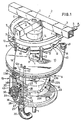
- the machine which is drawn in fig. 1, is provided with a central, stationary shaft 1 which is vertically adjustable, for example by means of a crank, a gearing and a toothed rack (not shown), mounted in a frame 2 (only partially shown), said frame consisting of hollow box girders (3).
- a rail 5 is suspended from the hollow box girders 3, said rail being part of a production line, along which several machines for processing slaughtered birds are disposed (not shown) and in which over the rail 5 carries 6 are movable which are interconnected by a chain (not shown), constituting the production line.
- the carriers 6 are movable over the rail 5 by means of rollers 7 at the inner side and the outer side.
- a cage 9 is rotatably mounted on the central shaft 1, said cage consisting of a top plate 10 and a bottom plate 11 interconnected by means of several, for example twelve peripherally spaced pairs of guide rods 12 and 12a.
- On the top plate 10 a carrying pin 13 is fixed engaging a bore 14 in a sprocket wheel 15 driven by the aforementioned chain in the direction of rotation R.
- a slide bearing (not shown) for the carrying pin 13 may optionally be mounted.
- the sprocket wheel 15 has teeth 16 and teeth cavities 17, the pitch of which corresponds to that of the carriers 6 on the chain (not shown). So the sprocket wheel 15 and therewith the cage 9 is driven around the central, stationary shaft 1 by the production line chain.
- a connecting rod 18 is pivotally suspended at each carrier 6, and at the bottom end of said rod a U-shaped leg hook 19 is suspended, the legs 20 of which are carried out double, said legs also being bent in U-shape at their free ends and said legs 20 at their free ends being bent slightly outwardly with respect to the machine, in such a manner that a slaughtered bird can be securely suspended with its ankle joints in the U-shaped legs 20 of the log hook 19.
- a slide 21 On the guide rods 12, 12a, a slide 21 is mounted which is slidable upwardly and downwardly.
- a follower roller 22 On the slide 21 a follower roller 22 is mounted on the side turned towards the central shaft 1 and cooperates with a curved track 23, said curved track 23 being formed on a cylindrical element 24, for example of nylon, said element being fixedly mounted on a drum 25, said drum in its turn being fixedly mounted on the central shaft 1.
- the curved track 23, seen in the direction of rotation R of the sprocket wheel 15 and the cage 9, consists of a horizontal, uppermost flat part 23a, a downwardly inclining part 23b, a horizontal lowermost flat part 23c and an upwardly inclining part 23d. The function thereof will be elucidated hereinafter.
- the cylindrical element 24 may be mounted adjustably in height direction and in peripheral direction on the drum 25.
- the guide rod 12a is carried out hollow over at least a part of its length and is at the level of the slide 21 provided with an opening 26 in its wall, while the lower end of the guide rod, approximately till the upper end of the opening 26 is carried out as a tube mounted in the bottom plate 11 and opening at the underside thereof.
- a distribution head 27 is mounted below the bottom plate 11 of the cage 9, said head being secured to the central shaft 1.
- the distribution head 27 is provided with a circularly bent, continuous longitudinal hole 28, to which in the position of the cage 9 as shown in fig. 1 the tubular end portion of the guide rod 12a is connected at the upper side of said hole 28, and said hole 28 at the lower side thereof is connected to a tube stub 29 secured to the distribution head 27, said tube stub 29 is connected to a vacuum source (not shown) by means of a corrugated tube 30.
- a short tubular piece 31 is mounted (vide also fig. 2) connecting in the position of the slide 21 shown in fig. 1 through the opening 26, the hollow guide rod 12a, the longitudinal hole 28, the tube stub 29 and the tube 30 to the vacuum source.
- a cylindrical sleeve 32 is mounted, in which a screw spindle 33 drivable around its longitudinal axis, is rotably mounted, the screw thread 34 of which is at least partially concentrically surrounded by the cylindrical sleeve 32, which has a radial clearance (s) with respect to the outer periphery of the screw thread 34.
- the radial clearance (s) between the outer periphery of the screw thread 34 on the screw spindle 33 and the inner wall of the cylindrical sleeve 32 is usually about two to four mm.
- the screw spindle 33 has a tapering infeed part 35 which has a spherical free end 36.
- the major part of the length of the screw thread 34 is limited at its outer periphery by a cylindrical plane 37 that is concentrical with respect to the axis of the screw spindle 33.
- the screw thread 34a on the tapering infeed part 35 of the screw spindle 33 is limited at its outer periphery by a conical plane 37a that is concentrical with respect to the axis of the screw spindle 33.
- the function and operation of the cylindrical sleeve 32 and of the screw spindle 33 will hereafter be elucidated in detail.
- the screw spindle 33 which is shaped hollow is drivably connected to and mounted axially slidable on a square drive shaft 38 which at its upper end is axially secured to and rotatably mounted with respect to the top plate 10.
- a drive pulley 39 is mounted which is carried out as a V-belt pulley and which is drivable by means of a V-belt 40 passed over a V-belt pulley 41 mouned on a motor shaft (not shown).
- the motor (not shown) can be mounted adjustably on the machine frame 2 to tension the V-belt 40.
- a U-shaped leg clip 42 is secured, which has at its upper end a part 43 bent at right angles, said part having the object to spread the legs P of the slaughtered bird V during the operation of the device, which will be elucidated hereafter in detail
- slaughtered birds V hang, or are being suspended with their ankle joints in the outwardly bend ends of the legs 20 of the leg hooks 19 and the carriers 6 of the conveyor belt travel at A on the rail 5.
- the follower roller 22 of the slide 21 travels on the uppermost flat part 23a of the curved track 23.
- the carriers 6 are engaging the teeth cavities 17 and the leg clips 42 with the horizontally bent part 43 engage between the legs P of the slaughtered birds V and spread the legs. Subsequently the carriers 6 rotate the sprocket wheel 15 and the cage 9 together with the slides 21, and the follower roller 22 moves on the downwardly inclining part 23b of the curved track 23, so that the screw spindle 33 with the infeed part 35 and the spherical free end 36 moves downwardly into the cut open bottom of the bird V.
- the rolling movement of the follower roller 22 on the downwardly inclining part 23b of the curved track 23 and thus the downward movement of the screw spindle 33 continues for such a period until the lower edge 32a of the sleeve 32 around the screw spindle 33 will rest on the bottom of the bird V, after which the downward movement of the slide 21 stops. In this manner the abutment in vertical direction is obtained for the slide 21 with the screw spindle 33 and the sleeve 32.
- the follower roller 22 is then preferably at some distance above the lowermost flat part 23c of the curved track 23, so that with a slaughtered bird V having longer legs P the slide 21 and thus the screw spindle 33 together with the sleeve 32 may move further downwardly.
- the position in height direction of the curved track 23 with respect to the slaughtered bird V is adjustable means of the above described adjustment device for the stationary central shaft 1.
- the screw spindle 33 is screwing the fat F upwardly out of the slaughtered bird V, at least a part of the skin S at the bottom of the bird being pulled upwardly into the clearance (s) between the screw-spindle 33 and the sleeve 32.
- this skin S which has the major part of the fat attached to it, is as it were, scraped off by the screw thread 34 of the screw spindle 33 which is limited by the cylindrical plane 37, so that a relatively sharp edge 37b is formed on the screw thread.
- the pin (not shown) mounted on the inner wall of the sleeve 32 and extending into the pitchless discharge groove 34b may promote the removal of the fat F from the screw thread 34, but in most cases such a pin is not needed.
- the horizontal tube piece 31 is connected to the opening 26 in the hollow guide rod 12a and as soon as the lower end of the hollow guide rod 12a reaches the opening 28 in the vacuum distribution head 27, the fat F is sucked by the vacuum from the tube piece 31 and from the pitchless discharge groove 34b into the hollow guide rod 12a, and is discharged through the opening 28, through the tube stub 29 and through the corrugated tube 30.
- the device for removing fat from slaughtered poultry need not be per se a part of a circular series of identical devices arranged as a roundabout, as described in the foregoing, but the device may also be applied for example as a hand drilling machine in a drill stand, the movement of the screw spindle 33 with the sleeve 32 surrounding the spindle being effected by a lever with a transmission mechanism
Landscapes
- Life Sciences & Earth Sciences (AREA)
- Engineering & Computer Science (AREA)
- Wood Science & Technology (AREA)
- Zoology (AREA)
- Food Science & Technology (AREA)
- Processing Of Meat And Fish (AREA)
- Housing For Livestock And Birds (AREA)
Claims (11)
Priority Applications (5)
| Application Number | Priority Date | Filing Date | Title |
|---|---|---|---|
| AT86201504T ATE48071T1 (de) | 1986-09-02 | 1986-09-02 | Vorrichtung und apparatur zum entfernen von fett von schlachtgefluegel. |
| EP86201504A EP0258499B1 (fr) | 1986-09-02 | 1986-09-02 | Dispositif et appareil pour enlever de la graisse de volailles abattues |
| DE8686201504T DE3667015D1 (en) | 1986-09-02 | 1986-09-02 | Apparatus and assembly to remove fat from slaughtered poultry |
| US07/088,355 US4776063A (en) | 1986-09-02 | 1987-08-24 | Method and apparatus for removing fat from slaughtered poultry |
| JP62218080A JPS63123334A (ja) | 1986-09-02 | 1987-09-02 | 屠殺された食用飼鳥類の肉から脂肪を除去する器具および機械 |
Applications Claiming Priority (1)
| Application Number | Priority Date | Filing Date | Title |
|---|---|---|---|
| EP86201504A EP0258499B1 (fr) | 1986-09-02 | 1986-09-02 | Dispositif et appareil pour enlever de la graisse de volailles abattues |
Publications (2)
| Publication Number | Publication Date |
|---|---|
| EP0258499A1 EP0258499A1 (fr) | 1988-03-09 |
| EP0258499B1 true EP0258499B1 (fr) | 1989-11-23 |
Family
ID=8195787
Family Applications (1)
| Application Number | Title | Priority Date | Filing Date |
|---|---|---|---|
| EP86201504A Expired EP0258499B1 (fr) | 1986-09-02 | 1986-09-02 | Dispositif et appareil pour enlever de la graisse de volailles abattues |
Country Status (5)
| Country | Link |
|---|---|
| US (1) | US4776063A (fr) |
| EP (1) | EP0258499B1 (fr) |
| JP (1) | JPS63123334A (fr) |
| AT (1) | ATE48071T1 (fr) |
| DE (1) | DE3667015D1 (fr) |
Families Citing this family (14)
| Publication number | Priority date | Publication date | Assignee | Title |
|---|---|---|---|---|
| US5154664A (en) * | 1990-10-29 | 1992-10-13 | Hazenbroek Jacobus E | Keel bone cutter with fat remover |
| NL9002471A (nl) * | 1990-11-12 | 1992-06-01 | Stork Pmt | Inrichting en werkwijze voor het verwijderen van abdominaal vet uit een geslachte vogel. |
| US5129856A (en) * | 1991-01-11 | 1992-07-14 | Seffelaar & Looyen, Inc. | Leaf lard starter |
| EP0461728A1 (fr) * | 1991-06-13 | 1991-12-18 | Machinefabriek Meyn B.V. | Dispositif d'ablation des intestins de volailles abattues |
| DE4138964C1 (fr) * | 1991-11-27 | 1992-12-17 | Nordischer Maschinenbau Rud. Baader Gmbh + Co Kg, 2400 Luebeck, De | |
| ES2125598T3 (es) * | 1994-01-18 | 1999-03-01 | Capital Formation Inc | Un aparato para empaquetar aves de corral y otros productos. |
| US5782056A (en) * | 1994-01-18 | 1998-07-21 | Delaware Capital Formation, Inc. | Packaging apparatus for removing a product from a continuously moving conveyor and sealing said product in a bag with a closure |
| EP0852464B1 (fr) * | 1995-09-27 | 1999-06-09 | Maja-Maschinenfabrik Hermann Schill GmbH | Procede et dispositif de desossage automatique de morceaux de viande, notamment de cuisses de volailles |
| DE69739576D1 (de) * | 1996-10-18 | 2009-10-22 | Systemate Bv | Genickbrechvorrichtung |
| US5997394A (en) * | 1999-03-18 | 1999-12-07 | Jarvis Products Corporation | Leaf lard remover |
| NL1014994C2 (nl) * | 2000-01-17 | 2001-07-18 | Stork Pmt | Werkwijze en inrichting voor het scheiden van buikvet van buikvel van gevogelte. |
| NL2008956C2 (en) * | 2012-06-07 | 2013-12-10 | Meyn Food Proc Technology Bv | Residual fat remover and method for removing residual fat of poultry fillets. |
| JP6401266B2 (ja) * | 2013-11-13 | 2018-10-10 | マレル・シュトルク・ポウルトリー・プロセシング・ベー・フェー | 羽根をむしり取ったホールレッグまたはドラムスティック鳥肉製品から皮を除去するためのシステム、方法およびカルーセル装置 |
| NL2015513B1 (en) * | 2015-09-28 | 2017-04-20 | Meyn Food Proc Technology Bv | Device and method for removing abdominal fat from abdominal skin of a slaughtered bird suspended by the legs. |
Citations (1)
| Publication number | Priority date | Publication date | Assignee | Title |
|---|---|---|---|---|
| NL7801689A (en) * | 1975-11-25 | 1978-05-31 | Meyn Pieter | Mechanically cutting open poultry - suspended from a transporter prior to removal of the intestines |
Family Cites Families (5)
| Publication number | Priority date | Publication date | Assignee | Title |
|---|---|---|---|---|
| US3705440A (en) * | 1971-01-21 | 1972-12-12 | Gainesville Machine Co Inc | Fowl vent removal apparatus and method |
| US3958303A (en) * | 1974-12-16 | 1976-05-25 | Gordon Johnson Company | Method and apparatus for poultry vent removal |
| US4208764A (en) * | 1976-12-17 | 1980-06-24 | Kjeld Loth | Poultry eviscerating method |
| US4117570A (en) * | 1977-07-25 | 1978-10-03 | Pieter Meyn | Apparatus for cutting out the vent of a fowl |
| NL8501556A (nl) * | 1985-05-30 | 1986-12-16 | Stork Pmt | Ontkroppingsmachine. |
-
1986
- 1986-09-02 DE DE8686201504T patent/DE3667015D1/de not_active Expired
- 1986-09-02 AT AT86201504T patent/ATE48071T1/de not_active IP Right Cessation
- 1986-09-02 EP EP86201504A patent/EP0258499B1/fr not_active Expired
-
1987
- 1987-08-24 US US07/088,355 patent/US4776063A/en not_active Expired - Lifetime
- 1987-09-02 JP JP62218080A patent/JPS63123334A/ja active Granted
Patent Citations (1)
| Publication number | Priority date | Publication date | Assignee | Title |
|---|---|---|---|---|
| NL7801689A (en) * | 1975-11-25 | 1978-05-31 | Meyn Pieter | Mechanically cutting open poultry - suspended from a transporter prior to removal of the intestines |
Also Published As
| Publication number | Publication date |
|---|---|
| US4776063A (en) | 1988-10-11 |
| JPS63123334A (ja) | 1988-05-27 |
| ATE48071T1 (de) | 1989-12-15 |
| DE3667015D1 (en) | 1989-12-28 |
| JPH028685B2 (fr) | 1990-02-26 |
| EP0258499A1 (fr) | 1988-03-09 |
Similar Documents
| Publication | Publication Date | Title |
|---|---|---|
| EP0258499B1 (fr) | Dispositif et appareil pour enlever de la graisse de volailles abattues | |
| EP0162154B1 (fr) | Dispositif d'ablation du goitre, de l'oesophage et de la région anale de volailles abattues | |
| DE69630178T2 (de) | Verfahren und Vorrichtung zum Bearbeiten von Schlachtgeflügel | |
| US4118829A (en) | Opening cut machine | |
| EP0245543B1 (fr) | Dispositif à ouvrir par découpe le corps d'une volaille | |
| CN1031013A (zh) | 从动物屠体段回收肉的工艺和装置 | |
| US3829933A (en) | Method and apparatus for eviscerating scallops | |
| US4229860A (en) | Cattle skinning process and apparatus therefor | |
| JPH01144920A (ja) | 家禽の体から皮をはぐ装置 | |
| CA1151822A (fr) | Appareil servant a eviscerer la volaille | |
| CN214178873U (zh) | 一种蛙类宰杀装置 | |
| US5186680A (en) | Poultry deskinning apparatus | |
| US3290722A (en) | Slitting device | |
| CN211631572U (zh) | 一种蛙类宰杀装置 | |
| US3571845A (en) | Chicken-slaughtering mechanism | |
| US7662031B1 (en) | Turkey breast defatter | |
| US6716096B2 (en) | Poultry feces removal apparatuses and methods | |
| EP0357843A1 (fr) | Dispositif pour transférer la volaille saignée | |
| EP0487075A1 (fr) | Installation pour abattoir | |
| CN111149843B (zh) | 一种蛙类宰杀装置 | |
| US3483590A (en) | Skinning machine | |
| JP4049489B2 (ja) | 魚類のピンボーン自動除去装置 | |
| IL37961A (en) | Machine and method for processing slaughtered poultry | |
| USRE31527E (en) | Method and apparatus for eviscerating scallops | |
| US3945084A (en) | Scallop spreading device |
Legal Events
| Date | Code | Title | Description |
|---|---|---|---|
| PUAI | Public reference made under article 153(3) epc to a published international application that has entered the european phase |
Free format text: ORIGINAL CODE: 0009012 |
|
| AK | Designated contracting states |
Kind code of ref document: A1 Designated state(s): AT BE CH DE FR GB IT LI LU NL SE |
|
| 17P | Request for examination filed |
Effective date: 19880204 |
|
| 17Q | First examination report despatched |
Effective date: 19880907 |
|
| GRAA | (expected) grant |
Free format text: ORIGINAL CODE: 0009210 |
|
| AK | Designated contracting states |
Kind code of ref document: B1 Designated state(s): AT BE CH DE FR GB IT LI LU NL SE |
|
| PG25 | Lapsed in a contracting state [announced via postgrant information from national office to epo] |
Ref country code: SE Effective date: 19891123 Ref country code: LI Effective date: 19891123 Ref country code: CH Effective date: 19891123 Ref country code: BE Effective date: 19891123 Ref country code: AT Effective date: 19891123 |
|
| REF | Corresponds to: |
Ref document number: 48071 Country of ref document: AT Date of ref document: 19891215 Kind code of ref document: T |
|
| ITF | It: translation for a ep patent filed | ||
| REF | Corresponds to: |
Ref document number: 3667015 Country of ref document: DE Date of ref document: 19891228 |
|
| REG | Reference to a national code |
Ref country code: CH Ref legal event code: PL |
|
| ET | Fr: translation filed | ||
| PLBE | No opposition filed within time limit |
Free format text: ORIGINAL CODE: 0009261 |
|
| STAA | Information on the status of an ep patent application or granted ep patent |
Free format text: STATUS: NO OPPOSITION FILED WITHIN TIME LIMIT |
|
| PG25 | Lapsed in a contracting state [announced via postgrant information from national office to epo] |
Ref country code: LU Free format text: LAPSE BECAUSE OF NON-PAYMENT OF DUE FEES Effective date: 19900930 |
|
| 26N | No opposition filed | ||
| ITTA | It: last paid annual fee | ||
| PGFP | Annual fee paid to national office [announced via postgrant information from national office to epo] |
Ref country code: GB Payment date: 19980824 Year of fee payment: 13 |
|
| PGFP | Annual fee paid to national office [announced via postgrant information from national office to epo] |
Ref country code: FR Payment date: 19980828 Year of fee payment: 13 |
|
| PGFP | Annual fee paid to national office [announced via postgrant information from national office to epo] |
Ref country code: NL Payment date: 19980930 Year of fee payment: 13 |
|
| PGFP | Annual fee paid to national office [announced via postgrant information from national office to epo] |
Ref country code: DE Payment date: 19990121 Year of fee payment: 13 |
|
| PG25 | Lapsed in a contracting state [announced via postgrant information from national office to epo] |
Ref country code: GB Free format text: LAPSE BECAUSE OF NON-PAYMENT OF DUE FEES Effective date: 19990902 |
|
| PG25 | Lapsed in a contracting state [announced via postgrant information from national office to epo] |
Ref country code: NL Free format text: LAPSE BECAUSE OF NON-PAYMENT OF DUE FEES Effective date: 20000401 |
|
| GBPC | Gb: european patent ceased through non-payment of renewal fee |
Effective date: 19990902 |
|
| PG25 | Lapsed in a contracting state [announced via postgrant information from national office to epo] |
Ref country code: FR Free format text: LAPSE BECAUSE OF NON-PAYMENT OF DUE FEES Effective date: 20000531 |
|
| NLV4 | Nl: lapsed or anulled due to non-payment of the annual fee |
Effective date: 20000401 |
|
| PG25 | Lapsed in a contracting state [announced via postgrant information from national office to epo] |
Ref country code: DE Free format text: LAPSE BECAUSE OF NON-PAYMENT OF DUE FEES Effective date: 20000701 |
|
| REG | Reference to a national code |
Ref country code: FR Ref legal event code: ST |
|
| PG25 | Lapsed in a contracting state [announced via postgrant information from national office to epo] |
Ref country code: IT Free format text: LAPSE BECAUSE OF NON-PAYMENT OF DUE FEES;WARNING: LAPSES OF ITALIAN PATENTS WITH EFFECTIVE DATE BEFORE 2007 MAY HAVE OCCURRED AT ANY TIME BEFORE 2007. THE CORRECT EFFECTIVE DATE MAY BE DIFFERENT FROM THE ONE RECORDED. Effective date: 20050902 |