EP0258058B1 - Vorrichtung zum Entwerfen - Google Patents
Vorrichtung zum Entwerfen Download PDFInfo
- Publication number
- EP0258058B1 EP0258058B1 EP87307598A EP87307598A EP0258058B1 EP 0258058 B1 EP0258058 B1 EP 0258058B1 EP 87307598 A EP87307598 A EP 87307598A EP 87307598 A EP87307598 A EP 87307598A EP 0258058 B1 EP0258058 B1 EP 0258058B1
- Authority
- EP
- European Patent Office
- Prior art keywords
- symbols
- sheets
- sheet
- elements
- draughting
- Prior art date
- Legal status (The legal status is an assumption and is not a legal conclusion. Google has not performed a legal analysis and makes no representation as to the accuracy of the status listed.)
- Expired
Links
- 239000000463 material Substances 0.000 claims abstract description 27
- 230000005291 magnetic effect Effects 0.000 claims description 19
- 238000000034 method Methods 0.000 claims description 17
- 238000003825 pressing Methods 0.000 claims description 5
- 239000000853 adhesive Substances 0.000 claims description 3
- 230000001070 adhesive effect Effects 0.000 claims description 3
- 238000004519 manufacturing process Methods 0.000 claims description 2
- 238000003860 storage Methods 0.000 claims description 2
- OKTJSMMVPCPJKN-UHFFFAOYSA-N Carbon Chemical compound [C] OKTJSMMVPCPJKN-UHFFFAOYSA-N 0.000 description 6
- 229910052799 carbon Inorganic materials 0.000 description 6
- 239000002184 metal Substances 0.000 description 3
- 230000000717 retained effect Effects 0.000 description 3
- 229920000642 polymer Polymers 0.000 description 2
- 238000006073 displacement reaction Methods 0.000 description 1
- 230000000694 effects Effects 0.000 description 1
- 230000005294 ferromagnetic effect Effects 0.000 description 1
- 238000012986 modification Methods 0.000 description 1
- 230000004048 modification Effects 0.000 description 1
- 125000006850 spacer group Chemical group 0.000 description 1
- 230000003068 static effect Effects 0.000 description 1
Images
Classifications
-
- B—PERFORMING OPERATIONS; TRANSPORTING
- B41—PRINTING; LINING MACHINES; TYPEWRITERS; STAMPS
- B41L—APPARATUS OR DEVICES FOR MANIFOLDING, DUPLICATING OR PRINTING FOR OFFICE OR OTHER COMMERCIAL PURPOSES; ADDRESSING MACHINES OR LIKE SERIES-PRINTING MACHINES
- B41L19/00—Duplicating or printing apparatus or machines for office or other commercial purposes, of special types or for particular purposes and not otherwise provided for
Definitions
- the present invention relates to draughting apparatus and in particular to apparatus for transferring symbols to a sheet(s) of paper or other draughting material for retaining a hard copy of an image.
- the apparatus is particularly, but not exclusively, suitable for transferring images of kitchen designs, bathroom designs, storage and supermarket shelving layouts, laundry equipment layouts, hospital ward layouts, office furnishing schemes, production bakery or factory layouts, cloakroom lockers and fittings layouts, military field issue maps showing symbol dispositions for immediate field issue, etc., interior furnishings and the like involving many different symbol configurations and layouts.
- An ideal interior design system should satisfy a number of criteria in addition to being inexpensive and easy to use. It should permit hard copies to be rapidly and easily made and should also permit more flexible designs to be made in a rapid and easy manner. Various copies should be made simultaneously without the requirement of a photocopier and then apparatus for fulfilling this function should be portable and easy to set up either in a studio or in an on-site environment.
- the system should have applicability to other areas such as games or any other environment where it is desired to transfer representatives of symbols to create a permanent image.
- the present invention provides a draughting apparatus comprising a plurality of substantially planar symbols elements having raised outlines for depicting predetermined symbols, a support panel means for supporting the symbols elements in a generally planar layout, said symbols elements being provided with symbol element locating means, and symbol transfer means comprising a self-duplicating set of sheets of draughting material having at least two sheets and a pressure transfer means, said at least two sheets being disposable between said raised outlines of said symbols elements and said pressure transfer means so that pressure applied by said pressure transfer means causes the outline of said symbols to be transferred to at least one of said two sheets to create an image of said symbols outlines thereon.
- a symbols support means in the form of a sheet of magnetic or magnetisable material and at least part of said symbols elements are, of a magnetisable or magnetic, respectively, material so that they are attracted to the sheet said at least part of said symbols elements and said sheet together comprising said symbol element locating means.
- a symbols locating means in the form of an adhesive sheet material attached to the back of the symbols elements so that they can be attached to and detached from said first sheet of said set.
- a symbols support means comprising a first component and the underside of each symbols element a second component, of a hook and loop type fastener system constituting said symbols locating means.
- the symbols elements may have any suitable type of symbol formed in raised outline thereon depending upon the particular application for which the apparatus is to be used.
- symbols representing kitchen items such as cupboards, appliances and the like, and/or symbols such as bathroom appliances or furniture.
- the apparatus uses a support sheet or panel means in the form of a drawing board provided with a sliding cursor, one side of the sliding cursor having a parallel edge and the other side of the cursor mounting a roller constituting the pressure transfer means, the cursor being rotatable through 180° so that the roller can be positioned to face the drawing board surface.
- a simple hand-held roller as a pressure transfer means though some care may need to be taken in detecting the position of the symbols elements under the draughting material and in avoiding accidental displacement of the symbols elements as a result of too much pressure being applied to the edge causing a "pushing" effect.
- a method of creating a fixed image made up of a plurality of symbols comprises the steps of providing an apparatus of the invention, positioning the symbols elements directly or indirectly on the support panel or sheet means, disposing said self-duplicating set of sheets of draughting material over said symbols elements, and applying pressure to said sheets of draughting material disposed on said symbols elements sufficient to transfer images of said symbols to at least one of said sheets of draughting material.
- draughting materials including paper and suitable films may be employed.
- various self-duplicating systems may be used including systems employing carbon paper or the like and most preferably systems using so-called NCR (no carbon required) or carbon-less paper.
- NCR no carbon required
- carbon-less paper a set provided with a top sheet of grid pattern or graph paper in order to facilitate quick and accurate drawing of symbol element locating guidelines etc. without the need for parallel motion rules or cursors or the like.
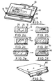
- FIG. 1 of the drawings depicts symbol transfer apparatus generally indicated by reference numeral 10 including a drawing board 12 having a slidable cursor 14.
- the drawing board 12 has a drawing surface 16 across which the cursor 14 slides on spaced mounts 18.
- the cursor consists of central support member 20 on which one side is secured a straight edge and the other side of which is secured to resilient pressure roller 24.
- the arrangement of the cursor is such that the roller and the parallel set can be rotated relative to the support so the pressure roller 24 facing the surface 16 for applying pressure to transfer an image of symbols onto paper as will be later described.
- the surface 16 is made of a resilient magnetic polymer for attraction to magnetic symbols 30,32 (Figs. 4 and 5). Shown on the surface of the drawing board is a sheet of self-duplicating paper 26 which has an outline 28 of a kitchen drawn thereon. Disposed within the outline of the kitchen are a plastic symbol 30,32 typical of kitchen units. As best seen in Figs. 4 and 5 the plastic symbols have a raised portion so that the symbol outline can generally be perceived.
- the rear surface 34 of the symbols is magnetic or metal for attraction to the backing sheet. It will be seen that by simply positioning the symbols within the outline of the kitchen they remain fixed in position because of magnetic attraction so that a plan of the kitchen can be obtained on the drawing board.
- Figs. 2(a) through 2(f) The procedure is best illustrated in Figs. 2(a) through 2(f). Firstly, as seen in Fig. 2(a) a panel 26 containing multi-sheet of self-duplicating paper is placed on top of the surface 16 of the drawing board 12, these are held in position by magnetic strip(s) and the outline 28 of the kitchen is drawn on the top sheet. The copies are laid aside for future duplicating, next magnetic symbols of kitchen equipment, such as a hob and sink are disposed within the outline of the kitchen as seen in Fig. 2(b). The remaining duplicating sheets 36 are positioned over the outline 18 of the kitchen and the magnetic symbols as seen in Fig. 2(c) and the cursor 14 is then reversed so that the roller 24 is in contact with the magnetic fixing strips which act as a spacer.
- the cursor is then firmly pressed and moved across the symbols and the duplicating paper 36 as shown in Fig. 2(e). This can be done several times to ensure that the outline of the symbols 30 are transferred to the duplicating paper 36.
- a small hand held roller may be used to pick up any small piece of detail the big roller has missed.
- the drawing board 12 and the symbols can be conveniently carried in a carrying case 40 as best seen in Fig. 3.
- a separate small business type case carries the symbols which are held in coded trays. It will be appreciated that this gives the system and apparatus portability so that design can be achieved within a customer's establishment.
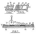
- Figs. 4 and 5 depict enlarged perspective views of typical symbols 30 and 32 as shown in Fig. 1.
- the symbols are made of plastic and have a magnetic base 34 which can be of magnetic polymer or a metal.
- the symbol 30 depicts a hob unit 32 and a sink unit.
- the edges of the hob and sink units 44 and 46 respectively are upstanding from the surface 48 of the symbols.
- the rings 50 are also upstanding from the surface 48 and similarly with the outline in the sink unit 52,54 and the draining tray 56.
- the invention has application in many fields in addition to kitchen planning and furniture layout. It could be used for copying, colour craftwork for a housing estate layout, boat or caravan layout or a children's toy or any subject involving arrangement of symbols on a plan with the requirement to keep a copy of the resulted plan.
- Advantages of the invention are that it is portable, quick, encourages customer participation forming a relationship, relatively inexpensive and the system is provided so that planning can be effective and a hard copy obtained.
- the system permits rapid and flexible design of different layouts in an efficient and straightforward manner without skilled operators.
- Fig. 7 shows a further embodiment generally similar to that of Fig. 1 having a flexible magnetic polymeric support sheet 60 which can conveniently be rolled up when not in use for ease of transportation and in use can be laid out on a rigid back support such as a table top 61.
- Rubber symbols elements 62 with backing sheets 63 of ferromagnetic metal are placed on the support sheet 60 and retained in position thereon by magnetic attraction between the symbols element backing sheets 63 and the support sheet 60 which together constitute symbols element locating means.
- a sheet of plain paper 64 and a sheet of carbon paper 65 which together constitute a self-duplicating set of sheets of draughting material which is retained in position on the support sheet 60 by ferrometallic or magnetic polymeric strips 66 along either edge 67.
- a further sheet 68 on which the framework has been previously drawn is placed immediately on top of the support sheet 60 and the symbols elements 62 positioned thereon.
- the transfer process is effected by passing the hand-held roller 69 more or less heavily across the assembly of sheets 65,64,68 symbols elements 62 and support sheet 60 so that printing ink is transferred from the carbon paper sheet 65 to the paper sheet 64 at the raised symbols outlines 70 on the upper faces 71 of the symbols elements 62.
- a top sheet 72 (indicated in dashed outline) of squared paper or the like which enables rectangular frames to be drawn out and measured thereon very easily, the framework being simultaneously transferred (by pressing suitably heavily with the drawing implement) onto the paper 64 and onto the further sheet 68 (with the aid of another carbon sheet 73 (indicated in chain-line).
- an apparatus of the invention can be used for various purposes.
- an apparatus of the invention could be used for at least some forms of 'sign-writing'.
Landscapes
- Decoration By Transfer Pictures (AREA)
- Table Devices Or Equipment (AREA)
- Internal Circuitry In Semiconductor Integrated Circuit Devices (AREA)
- Steering Control In Accordance With Driving Conditions (AREA)
- Printing Methods (AREA)
- Supplying Of Containers To The Packaging Station (AREA)
- Auxiliary Devices For And Details Of Packaging Control (AREA)
- Pinball Game Machines (AREA)
- Drawing Aids And Blackboards (AREA)
Claims (15)
- Zeichenvorrichtung (10) mit einer Mehrzahl von im wesentlichen ebenen Symbolelementen (30), die erhabene Konturen (70) zum Abbilden vorbestimmter Symbole (32) aufweisen, mit einem Halterungsmittel (12, 16), um die Symbolelemente (30) in einer generell ebenen Anordnung zu halten, wobei die Symbolelemente mit Symbolelementanordnungsmitteln (34, 16) versehen sind, und mit Symbolübertragungsmitteln, die einen selbstduplizierenden Bogensatz (36) von Zeichenmaterial, der mindestens zwei Bögen hat, sowie Druckübertragungsmittel (24) aufweisen, wobei die mindestens zwei Bögen (36) zwischen den erhabenen Konturen (70) der Symbolelemente (30) und den Druckübertragungsmitteln (24) angeordnet werden können, so daß über die Druckübertragungsmittel ausgeübter Druck die Übertragung der Konturen der Symbole (32) auf mindestens einen der beiden Bögen (36) hervorruft, um ein Bild der Symbolumrisse darauf zu erzeugen.
- Vorrichtung nach Anspruch 1, dadurch gekennzeichnet, daß das Symbolhalterungsmittel (12, 16) ein flächiges Element (60) aus magnetischem oder magnetisierbarem Material aufweist und daß mindestens Teile der Symbolelemente aus magnetisierbarem oder magnetischem Material sind, so daß sie von dem flächigen Element angezogen werden, wobei die mindestens Teile der Symbolelemente und das flächige Element zusammen die Symbolelement-Anordnungsmittel aufweisen.
- Vorrichtung nach Anspruch 1, dadurch gekennzeichnet, daß das Symbolanordnungsmittel (34) ein auf der Rückseite der Symbolelemente angebrachtes haftendes flächiges Material aufweist, so daß die Symbolelemente auf das erste Blatt des Satzes angesetzt und davon abgenommen werden können.
- Vorrichtung nach Anspruch 1, dadurch gekennzeichnet, daß das Symbolhalterungsmittel eine erste Komponente und die Unterseite eines jeden Symbolelements (30) eine zweite Komponente eines haken- und schlingenartigen Befestigungssystems, welches das Symbolanordnungsmittel bildet, aufweist.
- Vorrichtung nach Anspruch 2, dadurch gekennzeichnet, daß der Bogensatz (36) mindestens einen weiteren Bogen (68) aufweist, der zwischen dem Symbolhalterungsmittel und den Symbolelementen angeordnet werden kann, wobei die Symbolelemente vom Symbolelementanordnungsmittel auf dem weiteren Bogen in Position gehalten sind, und der weitere Bogen dazu verwendet werden kann, Symbolelementpositionsanzeigemittel darzustellenn.
- Vorrichtung nach Anspruch 5, dadurch gekennzeichnet, daß der selbstduplizierende Bogensatz von Zeichenmaterial einen Bogensatz von selbstduplizierendem Papier aufweist.
- Vorrichtung nach Anspruch 5, dadurch gekennzeichnet, daß der selbstduplizierende Bogensatz von Zeichenmaterial einen Bogen Papier und einen Bogen aus Drucktintenübertragungsmaterial aufweist.
- Vorrichtung nach Anspruch 6, dadurch gekennzeichnet, daß das Druckübertragungsmittel eine Walze (24) aufweist.
- Vorrichtung nach Anspruch 8, dadurch gekennzeichnet, daß die Halterungsfläche oder das Plattenmittel ein Zeichenbrett (12) aufweist, das einen Gleitläufer (14) hat, dessen eine Seite eine parallele Kante hat und an dessen anderer Seite die Walze (24) befestigt ist, wobei der Läufer um 180° drehbar ist, so daß die Walze so positioniert werden kann, daß sie an der Zeichenbrettfläche anliegt.
- Vorrichtung nach einem der Ansprüche 1 bis 9, dadurch gekennzeichnet, daß die erhabenen Konturen (70) maßstäblich verkleinerte Darstellungen von Einrichtungsgegenständen und/oder Haushaltsgeräten aufweisen.
- Vorrichtung nach Anspruch 10, dadurch gekennzeichnet, daß die Einrichtungsgegenstände und Haushaltsgeräte für Küche, Badezimmer, Lagerräume, Supermarkt, Wäscheraum, Krankenhausabteilung, Büro, Bäckerei, Fabrik, Boot, Karavan und/oder Garderobenraum sind.
- Vorrichtung nach Anspruch 11, dadurch gekennzeichnet, daß die Einrichtungsgegenstände und Haushaltsgeräte Kücheneinrichtungen und/oder Küchengeräte aufweisen.
- Verfahren zur Erzeugung eines festen Bildes, bestehend aus einer Mehrzahl von Symbolen, welches folgende Schritte aufweist:
man stellt eine Vorrichtung gemäß Anspruch 1 zur Verfügung,
man positioniert die Symbolelemente (30) direkt oder indirekt auf dem Halterungsmittel (12, 16) oder dem Bogenmittel,
man ordnet den selbstduplizierenden Bogensatz (36) von zeichenmaterial über den der Symbolelemente an, und
man wendet Druck an auf die Bögen von Zeichenmaterial, die auf den Symbolelementen angeordnet sind, der ausreicht, die Bilder der Symbole auf mindestens einen Bogen des Zeichenmaterials zu übertragen. - Verfahren zur Erzeugung eine festen Bildes nach Anspruch 13 zur Verwendung beim Entwerfen von Einrichtungen von Gebäuden oder Raumflächen, wobei eine Vorrichtung nach Anspruch 5 vorgesehen ist und das Verfahren die einleitenden Schritte umfaßt,
man zeichnet einen verkleinerten Umriß der Fläche auf einen selbstduplizierenden Bogensatz (36), um die Konturen auf mindestens einen Bogensatz (63) der selbstduplizierenden Bögen (36) und auf den weiteren Bogen (68) zu übertragen,
man nimmt den selbstduplizierenden Bogensatz auseinander, um den weiteren Bogen (68) aufzudecken,
man positioniert die Symbolelemente (30) auf dem Umriß auf dem weiteren Bogen (68) und
man setzt den selbstduplizierenden Bogensatz (36) mit den dazwischengelegten Symbolelementen (30) wieder zusammen,
wobei man einen Druck auf den selbstduplizierenden Bogensatz von Zeichenmaterial ausübt, der ausreicht, Bilder der Symbole (30) auf den mindestens einen von den Bögen von Zeichenmaterial (36) zu übertragen, wobei die Bilder auf dem Umriß des mindestens einen (63) der aufeinandergelegten Bögen von Zeichenmaterial (36) geformt werden. - Verfahren nach Anspruch 13 oder Anspruch 14, dadurch gekennzeichnet, daß eine Vorrichtung vorgesehen ist, in der die erhabenen Umrisse (70) maßstäblich verkleinerte Darstellungen von Einrichtungsgegenständen und/oder Haushaltsgeräten verkörpern.
Priority Applications (1)
| Application Number | Priority Date | Filing Date | Title |
|---|---|---|---|
| AT87307598T ATE65746T1 (de) | 1986-08-28 | 1987-08-27 | Vorrichtung zum entwerfen. |
Applications Claiming Priority (2)
| Application Number | Priority Date | Filing Date | Title |
|---|---|---|---|
| GB868620769A GB8620769D0 (en) | 1986-08-28 | 1986-08-28 | Symbol transfer apparatus |
| GB8620769 | 1986-08-28 |
Publications (2)
| Publication Number | Publication Date |
|---|---|
| EP0258058A1 EP0258058A1 (de) | 1988-03-02 |
| EP0258058B1 true EP0258058B1 (de) | 1991-07-31 |
Family
ID=10603303
Family Applications (1)
| Application Number | Title | Priority Date | Filing Date |
|---|---|---|---|
| EP87307598A Expired EP0258058B1 (de) | 1986-08-28 | 1987-08-27 | Vorrichtung zum Entwerfen |
Country Status (5)
| Country | Link |
|---|---|
| US (1) | US4896427A (de) |
| EP (1) | EP0258058B1 (de) |
| AT (1) | ATE65746T1 (de) |
| DE (1) | DE3771808D1 (de) |
| GB (1) | GB8620769D0 (de) |
Families Citing this family (5)
| Publication number | Priority date | Publication date | Assignee | Title |
|---|---|---|---|---|
| US5062356A (en) * | 1990-11-05 | 1991-11-05 | Armella Frankowski | Cookie baking apparatus |
| USD360075S (en) | 1994-02-03 | 1995-07-11 | Kensington Microware Limited | Compact computer carrying case |
| USD358483S (en) | 1994-03-04 | 1995-05-23 | Kensington Microware Limited | Computer carrying case |
| USD380612S (en) * | 1995-03-20 | 1997-07-08 | Kensington Microware Limited | Computer carrying case |
| DE202017000132U1 (de) | 2017-01-12 | 2018-04-15 | Küchenatlas Portal Betriebs GmbH | Planungsstation mit Touchscreen, 3D-Screen und Mustern |
Family Cites Families (10)
| Publication number | Priority date | Publication date | Assignee | Title |
|---|---|---|---|---|
| GB133543A (de) * | ||||
| US1964236A (en) * | 1934-04-06 | 1934-06-26 | Lourde J Welch | Printing |
| US2034584A (en) * | 1934-06-07 | 1936-03-17 | Herbert W Lamb | Show card machine |
| US2100114A (en) * | 1935-03-23 | 1937-11-23 | John P Walsh | Art of lining up printed matter and registering type |
| US2958948A (en) * | 1956-07-02 | 1960-11-08 | Martin Co | Drawing arrangement |
| US2994265A (en) * | 1959-03-25 | 1961-08-01 | Douglas H Hurlbut | Card printing machine |
| US3223454A (en) * | 1963-10-15 | 1965-12-14 | Dieffenbach Percy | Apparatus for making brushes |
| US3280738A (en) * | 1964-04-24 | 1966-10-25 | Signpress Company | Card holding means for card printing machine |
| US3862598A (en) * | 1973-07-16 | 1975-01-28 | Bartizan Corp | Printing device |
| US3890899A (en) * | 1974-02-25 | 1975-06-24 | Addressograph Multigraph | Card gage for data recorder |
-
1986
- 1986-08-28 GB GB868620769A patent/GB8620769D0/en active Pending
-
1987
- 1987-08-27 AT AT87307598T patent/ATE65746T1/de not_active IP Right Cessation
- 1987-08-27 EP EP87307598A patent/EP0258058B1/de not_active Expired
- 1987-08-27 DE DE8787307598T patent/DE3771808D1/de not_active Expired - Fee Related
-
1989
- 1989-02-23 US US07/316,543 patent/US4896427A/en not_active Expired - Fee Related
Also Published As
| Publication number | Publication date |
|---|---|
| US4896427A (en) | 1990-01-30 |
| ATE65746T1 (de) | 1991-08-15 |
| DE3771808D1 (de) | 1991-09-05 |
| EP0258058A1 (de) | 1988-03-02 |
| GB8620769D0 (en) | 1986-10-08 |
Similar Documents
| Publication | Publication Date | Title |
|---|---|---|
| US11517172B2 (en) | Cleaning system, cleaning devices, instruction insert, and methods therefor | |
| US4626218A (en) | Modular furniture design aid | |
| US11257398B2 (en) | Cleaning system, cleaning devices, instruction insert, and methods therefor | |
| US4852282A (en) | Magnetic calendar frame | |
| US4806102A (en) | Modular layout assembly | |
| US3456373A (en) | Decorative magnetic bulletin board | |
| US3755938A (en) | Graphmatic magnegraph | |
| EP0258058B1 (de) | Vorrichtung zum Entwerfen | |
| US3156056A (en) | Visual control board | |
| US3994079A (en) | Display device, particularly suitable for interior designs | |
| US5505620A (en) | Planning and toy assemblies, and the like, employing movable elements of permanent magnet material | |
| US4104810A (en) | Display device | |
| US9633571B2 (en) | Art instruction systems and methods using a border guide | |
| EP1495388A2 (de) | Dokumentanzeige- und halteeinrichtung | |
| US2984020A (en) | Method and apparatus for arrangement of furniture | |
| US20050277093A1 (en) | Furniture template | |
| US2895233A (en) | Coordinated news and map display device | |
| CA1283285C (en) | Modular furniture design aid | |
| JP4996993B2 (ja) | 清掃方法 | |
| US20190084343A1 (en) | Reconfigurable apparatus and system for marking and displaying of items | |
| JPH0627439Y2 (ja) | レイアウト用テンプレート | |
| US3507056A (en) | Educational display case | |
| Kirkpatrick et al. | Communicating nursing research through poster presentations | |
| US7475505B2 (en) | Display device | |
| Tauffner | Furniture and related facilities to accommodate multi-media activities in libraries |
Legal Events
| Date | Code | Title | Description |
|---|---|---|---|
| PUAI | Public reference made under article 153(3) epc to a published international application that has entered the european phase |
Free format text: ORIGINAL CODE: 0009012 |
|
| AK | Designated contracting states |
Kind code of ref document: A1 Designated state(s): AT BE CH DE ES FR GB IT LI LU NL SE |
|
| 17P | Request for examination filed |
Effective date: 19880811 |
|
| 17Q | First examination report despatched |
Effective date: 19900126 |
|
| 17Q | First examination report despatched |
Effective date: 19900531 |
|
| GRAA | (expected) grant |
Free format text: ORIGINAL CODE: 0009210 |
|
| AK | Designated contracting states |
Kind code of ref document: B1 Designated state(s): AT BE CH DE ES FR GB IT LI LU NL SE |
|
| PG25 | Lapsed in a contracting state [announced via postgrant information from national office to epo] |
Ref country code: IT Free format text: LAPSE BECAUSE OF FAILURE TO SUBMIT A TRANSLATION OF THE DESCRIPTION OR TO PAY THE FEE WITHIN THE PRE;WARNING: LAPSES OF ITALIAN PATENTS WITH EFFECTIVE DATE BEFORE 2007 MAY HAVE OCCURRED AT ANY TIME BEFORE 2007. THE CORRECT EFFECTIVE DATE MAY BE DIFFERENT FROM THE ONE RECORDED.SCRIBED TIME-LIMIT Effective date: 19910731 Ref country code: LI Effective date: 19910731 Ref country code: SE Effective date: 19910731 Ref country code: NL Effective date: 19910731 Ref country code: BE Effective date: 19910731 Ref country code: FR Effective date: 19910731 Ref country code: CH Effective date: 19910731 Ref country code: AT Effective date: 19910731 |
|
| REF | Corresponds to: |
Ref document number: 65746 Country of ref document: AT Date of ref document: 19910815 Kind code of ref document: T |
|
| PG25 | Lapsed in a contracting state [announced via postgrant information from national office to epo] |
Ref country code: LU Free format text: LAPSE BECAUSE OF NON-PAYMENT OF DUE FEES Effective date: 19910831 |
|
| REF | Corresponds to: |
Ref document number: 3771808 Country of ref document: DE Date of ref document: 19910905 |
|
| PG25 | Lapsed in a contracting state [announced via postgrant information from national office to epo] |
Ref country code: GB Effective date: 19911031 |
|
| PG25 | Lapsed in a contracting state [announced via postgrant information from national office to epo] |
Ref country code: ES Free format text: LAPSE BECAUSE OF FAILURE TO SUBMIT A TRANSLATION OF THE DESCRIPTION OR TO PAY THE FEE WITHIN THE PRESCRIBED TIME-LIMIT Effective date: 19911111 |
|
| REG | Reference to a national code |
Ref country code: CH Ref legal event code: PL |
|
| EN | Fr: translation not filed | ||
| NLV1 | Nl: lapsed or annulled due to failure to fulfill the requirements of art. 29p and 29m of the patents act | ||
| PG25 | Lapsed in a contracting state [announced via postgrant information from national office to epo] |
Ref country code: DE Effective date: 19920501 |
|
| PLBE | No opposition filed within time limit |
Free format text: ORIGINAL CODE: 0009261 |
|
| STAA | Information on the status of an ep patent application or granted ep patent |
Free format text: STATUS: NO OPPOSITION FILED WITHIN TIME LIMIT |
|
| GBPC | Gb: european patent ceased through non-payment of renewal fee | ||
| 26N | No opposition filed |