EP0257900A2 - Fenêtres chauffantes - Google Patents
Fenêtres chauffantes Download PDFInfo
- Publication number
- EP0257900A2 EP0257900A2 EP87307057A EP87307057A EP0257900A2 EP 0257900 A2 EP0257900 A2 EP 0257900A2 EP 87307057 A EP87307057 A EP 87307057A EP 87307057 A EP87307057 A EP 87307057A EP 0257900 A2 EP0257900 A2 EP 0257900A2
- Authority
- EP
- European Patent Office
- Prior art keywords
- window
- heating element
- grooves
- electrical heating
- optical
- Prior art date
- Legal status (The legal status is an assumption and is not a legal conclusion. Google has not performed a legal analysis and makes no representation as to the accuracy of the status listed.)
- Granted
Links
Images
Classifications
-
- B—PERFORMING OPERATIONS; TRANSPORTING
- B64—AIRCRAFT; AVIATION; COSMONAUTICS
- B64C—AEROPLANES; HELICOPTERS
- B64C1/00—Fuselages; Constructional features common to fuselages, wings, stabilising surfaces or the like
- B64C1/14—Windows; Doors; Hatch covers or access panels; Surrounding frame structures; Canopies; Windscreens accessories therefor, e.g. pressure sensors, water deflectors, hinges, seals, handles, latches, windscreen wipers
- B64C1/1476—Canopies; Windscreens or similar transparent elements
- B64C1/1492—Structure and mounting of the transparent elements in the window or windscreen
-
- H—ELECTRICITY
- H05—ELECTRIC TECHNIQUES NOT OTHERWISE PROVIDED FOR
- H05B—ELECTRIC HEATING; ELECTRIC LIGHT SOURCES NOT OTHERWISE PROVIDED FOR; CIRCUIT ARRANGEMENTS FOR ELECTRIC LIGHT SOURCES, IN GENERAL
- H05B3/00—Ohmic-resistance heating
- H05B3/84—Heating arrangements specially adapted for transparent or reflecting areas, e.g. for demisting or de-icing windows, mirrors or vehicle windshields
Definitions
- This invention relates to heated windows and in particular, but not exclusively, to optical equipment which is subjected to extreme environmental conditions.
- mist or ice may form on the surface of windows and impair the performance of optical equipment behind the window.
- a method of overcoming icing or fogging is to heat the window electrically.
- it is necessary to either avoid obscuring the window with heating elements or to minimise the effect.
- the surface of the window must be heated evenly so that the optical properties of the window remain uniform and this is difficult to achieve for large areas of window.
- wires are bonded onto the outside surface of the window; however this may cause smearing during wiping of the window and the wires could be damaged by the wiping.
- Another method is to bond wires to the inside surface of the windows. This enables the smooth outer surface to be wiped cleanly but a longer thermal path (i.e. the thickness of the window) is introduced between the elements and the outside surface of the window; consequently the window takes longer to de-ice and more energy is required.
- wires are sandwiched between two layers of glass. As it is important optically that the outer surfaces of the final assembly are parallel to each other, these faces must be re-ground and polished after assembly, and is therefore expensive.
- Another approach is to lay a conductive film over the entire surface of the window but this reduces the optical transmissive properties of the window by up to 30% at some wavelengths.
- an optical window member having an electrical heating element said window member including at least one groove provided in a surface of the window, and an electrically conducting heating element maintained within said grooves by means of adhesive material located substantially wholly within said grooves.
- an electrically heatable window comprising an optical radiation transmissive member which has two opposite surfaces and a peripheral surface extending between said two opposite surfaces, and an electrical heating element extending around said peripheral surface and fixed thereto by means of adhesive.
- an optical window member having a first electrical heating element, said window member including at least one groove provided in a surface of the window and said first electrical heating element being inlaid in said groove and maintained within said grooves by means of adhesive material located substantially wholly within said grooves and the window member having a second electrical heating element which is wound around the periphery of the window member and is bonded in place by means of adhesive.
- the conducting elements are arranged to include parallel portions extending at spaced intervals across the window.
- the conducting elements are arranged in parallel groups.
- the conducting elements in each group are arranged so that the total length of wire in a group is substantially the same as the total length of wire in any other group.
- the conducting elements are arranged to include parallel portions extending at spaced intervals across the window.
- the spacing of the intervals may be regular or irregular.
- the conducting elements may be electrically connected in parallel, series - parallel groups or in series, preferably the conducting elements in each group are arranged so that the total resistance of wire in a given group is substantially the same as the total resistance of wire in any other group.
- the circuit can be arranged to give any desired heat distribution.
- the present arrangement provides a smooth surface which can be easily wiped and in which the heating elements are in close contact with the deposits they are to disperse.
- the arrangement also enables a window to be de-iced rapidly.
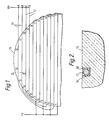
- FIG. 1 there is illustrated a first embodiment of heated window in which the heating element is placed in parallel grooves in the external surface of the window.
- the window 15 has a series of parallel slots 16 scored into one surface at a regular pitch to achieve a uniform temperature gradient across the surface of the window; however they may be irregularly spaced to create a different temperature gradient across the window.
- a further advantage of having irregularly spaced heating elements is that they disrupt the optical interference effects which might otherwise occur.
- the width of each slot must be minimal to reduce obscuration of the optical system and to improve thermal conduction from the wires.
- a wire 17 is placed in slot 16 and a low viscosity epoxy resin 18 or other suitable bonding agent is placed in the slot to bond the wire in place.
- the wires 17 are arranged in several groups over the area of the window.
- Figure 2 shows a group of four wires 17 in parallel on the upper part 15 of a window.
- a wire A is inlaid in slots 12, 2, and 1;
- a second wire B is inlaid in slots 11, 4, 3;
- a third wire C inlaid in slots 10, 6 and 5 and a fourth wire D inlaid in the slots 9, 8 and 7.
- the four wires in the group are the same length; however, because of the circular shape of the window the length of slots progressively increase down the window from slot 12 to slot 1.
- each wire is inlaid into a combination of slot lengths so that it traverses approximately the same length of window as the other wires and so that the total length of each combination of slots is approximately the same.
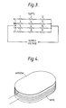
- Figure 3 is a schematic circuit diagram of the wiring arrangement in Figure 1 and shows how the group is connected in a series parallel arrangement.
- the wiring arrangement disclosed in Figures 1 and 3 is an optimum arrangement which enables a uniform heat distribution to be achieved across a window; at the same time if a wire in a group should fail the failure will be localised to the single wire in that group and the rest of the group will continue to function properly.
- a second embodiment of the invention is shown in figure 4 in which one or more coils of wire are wound around the periphery of the window and are adhered to the periphery by epoxy resin.
- a hybrid window is constructed by combining features from the other two windows.
- the window has wires inlaid in its surface which are supplemented by heating elements coiled around the periphery of the windows.
- the slots scored into the window need not be limited to straight parallel lines but could be cut to provide any number of variations or different designs to achieve different effects.
- the slots might be scored as a circle around the periphery of the window or as a circle or a series of concentric circles and the wires arranged in coiled formation within the circle or circles.
- the power density for a given window can be varied by using wire of a different resistivity and/or by varying the number of turns in each coil. Any cross-section of wire heating element can be used.
Landscapes
- Engineering & Computer Science (AREA)
- Mechanical Engineering (AREA)
- Aviation & Aerospace Engineering (AREA)
- Surface Heating Bodies (AREA)
- Resistance Heating (AREA)
Applications Claiming Priority (2)
| Application Number | Priority Date | Filing Date | Title |
|---|---|---|---|
| GB8619443 | 1986-08-08 | ||
| GB8619443A GB2193869B (en) | 1986-08-08 | 1986-08-08 | Heated windows |
Publications (3)
| Publication Number | Publication Date |
|---|---|
| EP0257900A2 true EP0257900A2 (fr) | 1988-03-02 |
| EP0257900A3 EP0257900A3 (en) | 1988-10-26 |
| EP0257900B1 EP0257900B1 (fr) | 1991-12-04 |
Family
ID=10602481
Family Applications (1)
| Application Number | Title | Priority Date | Filing Date |
|---|---|---|---|
| EP19870307057 Expired EP0257900B1 (fr) | 1986-08-08 | 1987-08-10 | Fenêtres chauffantes |
Country Status (4)
| Country | Link |
|---|---|
| US (1) | US4845344A (fr) |
| EP (1) | EP0257900B1 (fr) |
| DE (1) | DE3774968D1 (fr) |
| GB (1) | GB2193869B (fr) |
Cited By (1)
| Publication number | Priority date | Publication date | Assignee | Title |
|---|---|---|---|---|
| US8124868B2 (en) | 2008-12-16 | 2012-02-28 | Solutia Inc. | Thin film photovoltaic module with contoured deairing substrate |
Families Citing this family (11)
| Publication number | Priority date | Publication date | Assignee | Title |
|---|---|---|---|---|
| US5119215A (en) * | 1990-02-20 | 1992-06-02 | Thermo-O-Disc, Incorporated | LCD with self regulating PTC thermistor heating element |
| JPH0529067A (ja) * | 1991-07-25 | 1993-02-05 | Rohm Co Ltd | 加熱体の構造及びoa機器の加熱装置 |
| US6137086A (en) * | 1999-02-26 | 2000-10-24 | Libbey-Owens-Ford Co. | Vehicle window with heated wiper rest |
| DE19942038C1 (de) * | 1999-09-03 | 2000-10-05 | Webasto Dachsysteme Gmbh | Deckel eines öffnungsfähigen Fahrzeugdachs mit in seinen Kunststoffrahmen eingebettetem Heizelement |
| DE102005034155B3 (de) * | 2005-07-21 | 2006-11-16 | Eos Gmbh Electro Optical Systems | Vorrichtung zum schichtweisen Herstellen eines dreidimensionalen Objekts |
| CA2628517C (fr) * | 2007-10-17 | 2013-08-13 | Adm21 Co., Ltd. | Lame d'essuie-glace a elements chauffants |
| DE102007062047A1 (de) * | 2007-12-21 | 2009-07-16 | Osram Opto Semiconductors Gmbh | Kompaktgehäuse |
| GB0918228D0 (en) | 2009-10-19 | 2009-12-02 | Pilkington Group Ltd | Heatable glazing |
| FR2991243B1 (fr) * | 2012-05-30 | 2015-01-02 | Peugeot Citroen Automobiles Sa | Vitrage degivrant comprenant un panneau rainure, vehicule equipe de ce vitrage et procede de fabrication de ce vitrage. |
| DE102014107480B4 (de) * | 2014-05-27 | 2016-02-04 | Webasto SE | Kunststoffheckscheibe mit Heckscheibenheizung und Verfahren zur Herstellung derselben |
| US10079640B1 (en) * | 2014-07-31 | 2018-09-18 | Collinear Networks, Inc. | Window heater with reduced wavefront distortion |
Family Cites Families (10)
| Publication number | Priority date | Publication date | Assignee | Title |
|---|---|---|---|---|
| NL96071C (fr) * | ||||
| US1565046A (en) * | 1925-04-06 | 1925-12-08 | Homer S Bergdoll | Windshield heater |
| US1822884A (en) * | 1929-02-19 | 1931-09-15 | George J Creighton | Heater for automotive shields |
| DE928310C (de) * | 1940-08-23 | 1955-05-31 | Ver Glaswerke Gmbh | Elektrisch heizbare Glasscheibe |
| DE1968844U (de) * | 1967-05-23 | 1967-09-21 | Eltro G M B H & Co Ges Fuer St | Elektrische heizung fuer austrittsfenster oder frontlinsen optischer geraete. |
| US3484583A (en) * | 1968-07-23 | 1969-12-16 | Ppg Industries Inc | Combination of electrically heated transparent window and antenna |
| AU528976B2 (en) * | 1978-08-08 | 1983-05-19 | Sony Corporation | Receiver tuning with frequency synthesizer |
| US4250396A (en) * | 1979-09-04 | 1981-02-10 | Walter Leuca | Heated drafting board |
| DE2950321A1 (de) * | 1979-12-14 | 1981-06-19 | Kabel- und Metallwerke Gutehoffnungshütte AG, 3000 Hannover | Elektrisches flaechenheizelement |
| US4552611A (en) * | 1983-08-26 | 1985-11-12 | Astrolab Inc. | Conductor applying apparatus for rear window defrosters |
-
1986
- 1986-08-08 GB GB8619443A patent/GB2193869B/en not_active Expired - Lifetime
-
1987
- 1987-08-06 US US07/082,131 patent/US4845344A/en not_active Expired - Fee Related
- 1987-08-10 DE DE8787307057T patent/DE3774968D1/de not_active Expired - Fee Related
- 1987-08-10 EP EP19870307057 patent/EP0257900B1/fr not_active Expired
Cited By (1)
| Publication number | Priority date | Publication date | Assignee | Title |
|---|---|---|---|---|
| US8124868B2 (en) | 2008-12-16 | 2012-02-28 | Solutia Inc. | Thin film photovoltaic module with contoured deairing substrate |
Also Published As
| Publication number | Publication date |
|---|---|
| EP0257900A3 (en) | 1988-10-26 |
| GB8619443D0 (en) | 1986-12-17 |
| US4845344A (en) | 1989-07-04 |
| GB2193869B (en) | 1990-03-21 |
| EP0257900B1 (fr) | 1991-12-04 |
| GB2193869A (en) | 1988-02-17 |
| DE3774968D1 (de) | 1992-01-16 |
Similar Documents
| Publication | Publication Date | Title |
|---|---|---|
| US4737618A (en) | Heating element for a defrosting device for a wing structure, such a device and a process for obtaining same | |
| US4845344A (en) | Heated windows | |
| KR101004171B1 (ko) | 발열체 및 이의 제조방법 | |
| US4388522A (en) | Electrically heated backlite structure | |
| US4278875A (en) | Electrically heated window | |
| US3484583A (en) | Combination of electrically heated transparent window and antenna | |
| US4396826A (en) | Lightweight heated plastic window element with unique bus bar system | |
| JP6978940B2 (ja) | 加熱可能なガラスパネル | |
| US3729616A (en) | Electrically heated window | |
| US4323726A (en) | Electrical bus bar assembly | |
| CA1320527C (fr) | Barre omnibus pour transparent chauffe | |
| US8841585B2 (en) | Transparent article which can be electrically extensively heated, method for the production thereof and the use thereof | |
| US2932710A (en) | Construction in electrically conducting transparent panel | |
| US2813960A (en) | Electric surface heater | |
| US5268531A (en) | Flat cable | |
| US9673534B2 (en) | Heatable window with high-pass frequency selective surface | |
| EP0627748A2 (fr) | Câble plat | |
| US20070108175A1 (en) | Heated laminated glazing | |
| US3022412A (en) | Deicer | |
| BRPI0707182A2 (pt) | vidraça transparente munida de um sistema estratificado aquecedor | |
| CN1141616A (zh) | 使用股绞电阻线的可变功率密度加热 | |
| BR112017003514B1 (pt) | Painel com uma região de aquecimento elétrico, método para a produção de um painel e uso do painel | |
| JPH10189232A (ja) | 積層透明体 | |
| US20210039358A1 (en) | Automotive laminate camera heating system with low distortion | |
| US4788629A (en) | Instrument panel members |
Legal Events
| Date | Code | Title | Description |
|---|---|---|---|
| PUAI | Public reference made under article 153(3) epc to a published international application that has entered the european phase |
Free format text: ORIGINAL CODE: 0009012 |
|
| AK | Designated contracting states |
Kind code of ref document: A2 Designated state(s): DE FR GB |
|
| PUAL | Search report despatched |
Free format text: ORIGINAL CODE: 0009013 |
|
| AK | Designated contracting states |
Kind code of ref document: A3 Designated state(s): DE FR GB |
|
| 17P | Request for examination filed |
Effective date: 19881116 |
|
| 17Q | First examination report despatched |
Effective date: 19891130 |
|
| GRAA | (expected) grant |
Free format text: ORIGINAL CODE: 0009210 |
|
| AK | Designated contracting states |
Kind code of ref document: B1 Designated state(s): DE FR GB |
|
| ET | Fr: translation filed | ||
| REF | Corresponds to: |
Ref document number: 3774968 Country of ref document: DE Date of ref document: 19920116 |
|
| PG25 | Lapsed in a contracting state [announced via postgrant information from national office to epo] |
Ref country code: GB Effective date: 19920810 |
|
| PGFP | Annual fee paid to national office [announced via postgrant information from national office to epo] |
Ref country code: FR Payment date: 19920831 Year of fee payment: 6 |
|
| RAP4 | Party data changed (patent owner data changed or rights of a patent transferred) |
Owner name: BRITISH AEROSPACE PUBLIC LIMITED COMPANY |
|
| PLBE | No opposition filed within time limit |
Free format text: ORIGINAL CODE: 0009261 |
|
| STAA | Information on the status of an ep patent application or granted ep patent |
Free format text: STATUS: NO OPPOSITION FILED WITHIN TIME LIMIT |
|
| PGFP | Annual fee paid to national office [announced via postgrant information from national office to epo] |
Ref country code: DE Payment date: 19921102 Year of fee payment: 6 |
|
| 26N | No opposition filed | ||
| GBPC | Gb: european patent ceased through non-payment of renewal fee |
Effective date: 19920810 |
|
| PG25 | Lapsed in a contracting state [announced via postgrant information from national office to epo] |
Ref country code: FR Effective date: 19940429 |
|
| PG25 | Lapsed in a contracting state [announced via postgrant information from national office to epo] |
Ref country code: DE Effective date: 19940503 |
|
| REG | Reference to a national code |
Ref country code: FR Ref legal event code: ST |