EP0257726A2 - Prüfung der Fehlereigenschaft eines Kippgenerators - Google Patents
Prüfung der Fehlereigenschaft eines Kippgenerators Download PDFInfo
- Publication number
- EP0257726A2 EP0257726A2 EP87301946A EP87301946A EP0257726A2 EP 0257726 A2 EP0257726 A2 EP 0257726A2 EP 87301946 A EP87301946 A EP 87301946A EP 87301946 A EP87301946 A EP 87301946A EP 0257726 A2 EP0257726 A2 EP 0257726A2
- Authority
- EP
- European Patent Office
- Prior art keywords
- signal
- sweep
- output signal
- input data
- magnitude
- Prior art date
- Legal status (The legal status is an assumption and is not a legal conclusion. Google has not performed a legal analysis and makes no representation as to the accuracy of the status listed.)
- Withdrawn
Links
- 238000012512 characterization method Methods 0.000 title description 42
- 238000010894 electron beam technology Methods 0.000 claims abstract description 13
- 230000001960 triggered effect Effects 0.000 claims abstract description 8
- 238000000034 method Methods 0.000 claims description 29
- 230000008859 change Effects 0.000 claims description 18
- 230000004044 response Effects 0.000 claims description 7
- 239000013078 crystal Substances 0.000 claims description 4
- 230000000737 periodic effect Effects 0.000 claims 18
- 238000006243 chemical reaction Methods 0.000 claims 10
- 238000012544 monitoring process Methods 0.000 claims 1
- 239000003990 capacitor Substances 0.000 description 48
- 238000005259 measurement Methods 0.000 description 15
- 238000006073 displacement reaction Methods 0.000 description 11
- 230000014509 gene expression Effects 0.000 description 9
- 230000008569 process Effects 0.000 description 9
- 230000001276 controlling effect Effects 0.000 description 6
- 230000000694 effects Effects 0.000 description 6
- 238000010586 diagram Methods 0.000 description 5
- 230000001934 delay Effects 0.000 description 4
- 238000012360 testing method Methods 0.000 description 4
- 230000006870 function Effects 0.000 description 3
- 230000000977 initiatory effect Effects 0.000 description 3
- 230000008878 coupling Effects 0.000 description 2
- 238000010168 coupling process Methods 0.000 description 2
- 238000005859 coupling reaction Methods 0.000 description 2
- 238000012986 modification Methods 0.000 description 2
- 230000004048 modification Effects 0.000 description 2
- 230000002730 additional effect Effects 0.000 description 1
- 230000032683 aging Effects 0.000 description 1
- 238000013459 approach Methods 0.000 description 1
- 238000012937 correction Methods 0.000 description 1
- 230000003247 decreasing effect Effects 0.000 description 1
- 229920005994 diacetyl cellulose Polymers 0.000 description 1
- 238000007599 discharging Methods 0.000 description 1
- 238000012804 iterative process Methods 0.000 description 1
- 238000009533 lab test Methods 0.000 description 1
- 230000008520 organization Effects 0.000 description 1
- 230000036961 partial effect Effects 0.000 description 1
- 229940086255 perform Drugs 0.000 description 1
- 238000010408 sweeping Methods 0.000 description 1
- 230000036962 time dependent Effects 0.000 description 1
Images
Classifications
-
- G—PHYSICS
- G01—MEASURING; TESTING
- G01R—MEASURING ELECTRIC VARIABLES; MEASURING MAGNETIC VARIABLES
- G01R13/00—Arrangements for displaying electric variables or waveforms
- G01R13/20—Cathode-ray oscilloscopes
- G01R13/22—Circuits therefor
- G01R13/24—Time-base deflection circuits
Definitions
- the present invention relates in general to sweep generators and in particular to a method and apparatus for producing a set of parameters characterizing gain and offset errors in a sweep generator output.
- Oscilloscopes typically employ at least one sweep generator to produce a voltage ramp output signal ("a sweep signal”) for controlling the horizontal movement (“the sweep”) of an electron beam across the screen of a cathode ray tube.
- a sweep signal a voltage ramp output signal
- the sweep the horizontal movement
- the resulting waveform display on the screen represents the magnitude of the input signal as a function of time.
- the oscilloscope sweep generator initially maintains the sweep signal at a constant, predetermined starting level until the sweep is initiated by a trigger signal. Thereafter, the sweep signal voltage rises with a constant slew rate to a predetermined ending level. Then the sweep signal returns to its starting level and remains there until the sweep is retriggered.
- the horizontal position of the beam on the screen is proportional to the sweep signal voltage, and the nominal starting and ending levels of the sweep signal may be chosen so that the beam nominally starts and ends on the left and right edges of a grid superimposed on a waveform display area of the oscilloscope screen.
- the trigger signal initiating the sweep is typically generated when the input signal reaches a predetermined trigger level, so the trigger point on the resulting waveform display can be nominally located at the left edge of the grid.
- the grid divides the display area into regular vertical and horizontal divisions to enable an operator to gauge, for any point on the waveform, its magnitude and horizontal displacement from the left edge of the grid.
- the time delay between the trigger point and a subsequent point of interest along a waveform is typically determined by dividing the displacement (in grid divisions) of the point of interest from the left edge of the grid by the nominal "sweep rate" of the beam, a measure of the speed at which the beam travels across the screen expressed in terms of grid divisions per unit time.
- the accuracy of such time delay determination is affected not only by the accuracy with which the operator can gauge the horizontal displacement of the point on the screen, but also by the accuracy of the sweep signal.
- the start of the sweep does not really line up with the left edge of the grid and the sweep has an "offset error".
- the sweep signal has a "sweep rate" error. Either type of error will cause an error in a time delay determination since the determination would assume the actual sweep signal starting level and sweep rate match their nominal values.
- a sweep signal controls the horizontal position of an electron beam on a cathode ray tube screen while an input signal controls the vertical position of the beam.
- the sweep signal is triggered by an event, e.g. in the input signal, the sweep signal magnitude increases from a starting level toward an ending level, desirably with a constant slew rate so as to sweep the beam across the screen at a constant horizontal speed.
- the beam is momentarily intensified to create a bright spot on the resulting waveform display when the sweep signal magnitude equals the output level of a digital-to-analog converter (DAC), controlled by DAC input data supplied by a microcomputer within the oscilliscope.
- DAC digital-to-analog converter
- a microcomputer computes the delay time between the start of the sweep (which suitably corresponds to the triggering event in the input signal) and the point along the waveform display indicated by the bright spot, the computation being based on measured "sweep gain” (G) and “sweep start” (Vo) parameters characterizing the sweep signal, and on the value of the input data (D) supplied to the DAC.
- the sweep start parameter Vo may be expressed in terms of "DAC units" and is the value of DAC input data which would cause the DAC to produce an output voltage equal to the actual (rather than nominal) starting level of the sweep signal.
- the sweep gain G can be expressed in terms of DAC units per second and indicates the rate of increase in DAC input data required to produce a DAC output signal having a rate of change similar to the slew rate of the actual sweep signal.
- the sweep gain G is accurately measured utilizing a square-wave characterization signal of a known frequency to trigger the sweep on the leading edge of a first pulse of the characterization signal.
- the DAC input data is initially set at a value which would be required to produce a DAC output signal equal to the nominal (expected) magnitude of the sweep signal after the sweep signal has increased for one half period of the characterization signal.
- a first comparator clocks a type D flip-flop when the sweep signal exceeds the DAC output signal, and a second comparator compares the characterization signal with a trigger level signal and drives its output high when the characterization signal is high, and low when the characterization signal is low.
- the output of the second comparator drives the D input of the flip-flop having a Q output providing an input to the microcomputer and having a reset controlled by the microcomputer.
- the microcomputer adjusts the data supplied to the DAC up or down depending on whether the Q output of the flip-flop is high or low, i.e., depending on whether the calibration signal was high or low when the sweep signal reached the DAC output level.
- the adjustments made to the DAC input data after each sweep areprogressively smaller until the adjustment amount is less than the least significant digit of the DAC input data. At that point the final adjusted value of the DAC input data represents the data value (VL) which would be required to produce a DAC output signal substantially equal to the actual sweep magnitude signal after the sweep signal has increased from its starting level for one half period of the characterization signal.
- the microcomputer sets the DAC input data to a value which causes the DAC to produce an output signal equal to the nominal (expected) magnitude of the sweep signal after the sweep signal has increased for three half periods of the characterization signal.
- the last adjusted value of the DAC input data represents the data value (VH) which would be required to produce a DAC output signal substantially equal to the actual magnitude of the sweep signal after the sweep signal has increased from its starting level for three half periods of the characterization signal.
- a high accuracy, crystal-controlled square-wave generator is mounted within the oscilloscope chassis with its output multiplexed with trigger signal inputs of the sweep generator, and the microcomputer is adapted to perform the above described characterization procedure automatically so that the values of G and Vo may be determined frequently and quickly on command of the operator, without need for additional test instrumentation.
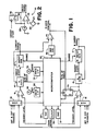
- FIG. 1 depicts in block diagram form a portion of an oscilloscope including an "A" sweep generator 10 and a “B" sweep generator 12, each adapted to produce a voltage ramp (sweep signal) output transmitted to horizontal amplifier circuits controlling the horizontal movement ("the sweep") of an electron beam across the screen of a cathode ray tube.
- the horizontal sweep rate of the beam is proportional to the slew rate of a selected one of the sweep signals.
- a resulting waveform display on the screen represents the magnitude of the input signal as a function of time.
- the A and B sweep generators 10 and 12 have independently adjustable slew rates and may provide sweep control for separate traces in a multiple trace oscilloscope.
- the A sweep generator 10 initially maintains its sweep signal output at a constant, predeter necessarilymined starting level until the sweep is initiated by a sweep start signal from an "A gate" circuit 14 which generates the sweep start signal when the output of a trigger level comparator 16 goes high.
- DAC digital-to-analog converter
- the A gate circuit 14 transmits the sweep start signal to the A sweep generator circuit 10. Thereafter, its sweep signal output voltage rises with a substantially constant slew rate set by a range control signal from microcomputer 22. The sweep signal is fed back to the A gate circuit 14 which ignores the output of comparator 16 after the sweep signal has been initiated until the the sweep signal reaches a predetermined upper limit. At this point, the A gate circuit 14 terminates the sweep start signal, transmits an "end of sweep" signal to microcomputer 22, and subsequently waits until comparator 16 indicates occurrence of another trigger before reinitiating the sweep start signal. Termination of the sweep start signal (at end of sweep) causes the sweep generator 10 to reset the sweep signal to its starting level and to maintain the sweep signal at this level until the sweep is subsequently restarted by the sweep start signal.
- the B sweep circuitry associated with B sweep generator 12 includes a B gate circuit 15, a comparator 17, a multiplexer 19 and a DAC 21, controlled by microcomputer 22, all of which operate in a fashion similar to gate circuit 14, comparator 16, multiplexer 18 and DAC 20 of the A sweep circuitry to produce the B sweep signal.
- FIG. 2 is a simplified schematic diagram of the A sweep generator 10 including an operational amplifier 24 for producing the sweep signal as its output, a capacitor 26 coupling the output of amplifier 24 to its inverting input, a current source 28 also connected to the amplifier inverting input, an offset voltage source 29 connected to the amplifier noninverting input, and a switch 30 for selectively coupling the output of amplifier 24 to its noninverting input. When switch 30 is closed, capacitor 26 is discharged and the output of amplifier 24 is held at the offset voltage output Voff of voltage source 29.
- switch 30 opens switch 30, whereupon amplifier 24 and capacitor 26 act in a well-known fashion as a Miller integrator to linearly increase the sweep signal output from the starting level Voff as capacitor 26 is charged by current from current source 28.
- switch 30 closes, rapidly dis charging capacitor 26 to drive the sweep signal output of amplifier 24 back to its starting level (Voff) and to maintain it there until the sweep start signal is initiated again.
- the actual starting level of the sweep signal can vary from the nominal starting level Voff due to inaccuracies in the output voltage of voltage source 29 and also due to inherent offset voltages in amplifier 24.
- the slew rate of the sweep signal is equal to the current produced by current source 28, divided by the capacitance of capacitor 26.
- sweep circuits for microcomputer-based oscilloscopes typically permit any one of several different capacitors and any one of several different current sources to be connected to amplifier 24 as capacitor 26 and current source 28 through microcomputer controlled switches.
- the various combinations of capacitance and current enables the microcomputer 22 of FIG. 1 to select any of several nominal slew rates for the sweep signal.
- any variation in the actual value of capacitor 26 or in the current produced by current source 28 from their nominal values causes the actual slew rate to differ from the nominal slew rate of the sweep signal.
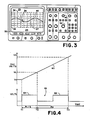
- FIG. 3 shows a front view of an oscilloscope including a screen 32 having a waveform display area 27 and areas 23 and 25 above and below the waveform display area for displaying data, menus and other information.
- a grid 36 superimposed over the waveform display area 27 divides the display area into regular vertical and horizontal "divisions" to enable an operator to gauge the magnitude and horizontal position of a point 38 on the waveform display 40.
- the horizontal position of the beam on the oscilloscope screen is proportional to the sweep signal voltage, and the nominal starting and ending levels of the sweep signal are suitably chosen so as to correspond to the left and right edges of the waveform display area 27, delimited by the left and right edges of grid 36.
- the trigger point on the waveform display i.e., the point on the waveform display corresponding to the point on the input signal which initiated the sweep start signal
- the trigger point on the waveform display can be nominally located at the left edge 42 of the grid 36.
- a time delay between the trigger point and point 38 along waveform display 40 can be approximately determined by dividing the horizontal displacement of point 38 from the left edge 42 of the grid by the nominal "sweep rate" of the beam.
- the "sweep rate” is proportional to the nominal slew rate of the sweep generator output signal and, being a measure of the nominal speed at which the beam travels across the screen, may be expressed in terms of grid divisions per unit time.
- the accuracy of this manual time delay determination depends in part of the accuracy with which the sweep generator 10 controls the starting level and slew rate of the sweep signal.
- the sweep generator output signal has an "offset error", wherein the actual starting level of the sweep does not correspond to the nominal (expected) starting level, the starting position of the waveform display will be offset from the left edge 42 of grid 36 such that the entire waveform display, including point 38, will be shifted to the right or to the left with respect to the grid.
- the sweep signal may also have a "sweep rate error" wherein the actual sweep rate of the sweep signal does not match its nominal value. Since offset and sweep rate errors are normally present, the delay time between the trigger point and point 38 calculated on the basis of the observed position of point 38 on the grid and the nominal sweep rate of the beam is subject to error.
- the sweep signal output of the A sweep generator 10 in addition to being supplied to the oscilloscope's horizontal preamplifier for controlling beam position, is also supplied to the inverting input of a comparator 44.
- the output of a "reference" DAC 46 is applied to the noninverting input of comparator 44, the DAC 46 output signal magnitude being proportional to digital data supplied to the DAC input by microcomputer 22.
- the output of comparator 44 provides an input to "Z-axis" circuitry of the oscilloscope controlling the intensity of the electron beam.
- An operator rotates a "reference" control knob 48 mounted on the front panel of the oscilloscope to provide input through knob interface circuitry 50 to the microcomputer 22 which adjusts the data supplied to the reference DAC 46 so as to move the bright spot in proportion to knob rotation.
- the operator may position the bright spot anywhere along the waveform utilizing knob 38.
- the microcomputer 22 also sets the sweep rate of the A sweep generator 10 through a range control signal to the sweep generator which connects a selected combination of capacitor and current source to the amplifier 24 of FIG. 2.
- the operator may select the sweep rate for the A sweep generator utilizing a sweep range control knob 52, also mounted on the front panel of the oscilloscope, to provide a sweep rate selection signal to the microcomputer 22 through knob interface circuitry 53.
- the microcomputer 22 can determine the nominal displacement of the bright spot from the left edge of the grid based on data supplied to the reference DAC 46, and since the microcomputer knows the nominal sweep rate from the sweep range setting, it could be programmed to divide the nominal displacement by the nominal sweep rate in order to determine the approximate time delay between the trigger event which caused initiation of the sweep and the point of interest in the input waveform corresponding to the highlighted point 38 of the waveform display.
- the microcomputer calculated delay time would also be subject to error insofar as the sweep signal is subject to offset and sweep rate errors.
- microcomputer 22 is adapted to compute the delay time between the actual trigger point on the input signal and the point along the input waveform corresponding to the point 38 indicated by the bright spot based on measured "sweep start” (Vo) and “sweep gain” (G) parameters characterizing the sweep signal, and on the value (D) of the data supplied as input to the reference DAC 46 to set the current position of the bright spot.
- the sweep start parameter Vo is expressed in terms of "DAC units” and is the value of DAC 46 input data which would cause DAC 46 to produce an output voltage equal to the actual (rather than nominal) starting level of the sweep signal.
- the sweep gain G is expressed in terms of "DAC units per second" and indicates the rate of increase in DAC 46 input data required to produce a DAC output signal which increases at a rate similar to the slew rate of the sweep signal.
- the sweep signal is characterized by a starting DAC input data value (Vo) and a rate of change of DAC input data value (G) which would cause the DAC to produce an output signal having a similar starting level and slew rate as the actual starting level and slew rate of the sweep signal.
- the Vo, G, and D parameters are then utilized to compute Td.
- Vo and G are determined utilizing a type D flip-flop 54 and a programmable clock 56, included in the oscilloscope circuitry as shown in FIG. 1.
- the output of comparator 44 drives the clock input of flip-flop 54
- the microcomputer 22 controls the reset (R) input
- the output of the B sweep circuit comparator 17 controls the D input.
- the Q output of flip-flop 54 is transmitted to the microcomputer 22.
- the microcomputer 22 controls the period of a square-wave "characterization" signal produced by clock 56, and the characterization signal is provided as an additional trigger source input to both multiplexers 18 and 19.
- the microcomputer 22 initiates measurement of the sweep gain and sweep start parameters G and Vo by setting multiplexers 18 and 19 to connect the characterization signal output of clock 56 to the noninverting inputs of comparators 16 and 17, and by setting the trigger level outputs of DACs 20 and 21 such that the square-wave signal produced by clock 56 drives the outputs of comparators 16 and 17 high on the leading edges of its pulses, and low on the trailing edges.
- the microcomputer 22 also sets the input data to DAC 46 to a value which would cause the DAC 46 to produce an output signal of magnitude near the nominal value to which the sweep signal would rise one half period of the characterization signal following sweep triggering on the leading edges of characterization signal pulses.
- FIG. 4 includes a graph of the A sweep signal 60 and a graph of the magnitude of the characterization signal 66 as functions of time.
- the magnitude of the characterization signal 66 is expressed as a voltage.
- the magnitude of the sweep signal is expressed not in voltage, but in equivalent "DAC units". Since the output voltage of DAC 46 is proportional to the magnitude of its input data, it is convenient to express a particular DAC 46 or A sweep generator 10 output voltage in terms of the magnitude of DAC 46 input data ("DAC units”) which would cause the DAC 46 to produce the particular voltage.
- flip-flop 54 If the output of comparator 17 is low when flip-flop 54 is set, flip-flop 54 is reset. After the end of each sweep, as indicated by the end of sweep signal provided by the A gate circuit 14, the microcomputer 22 reads the state of flip-flop 54 and then resets it.
- the microcomputer 22 adjusts the input data supplied to DAC 46 up or down depending on whether the Q output of the flip-flop is high or low, i.e., depending on whether or not the trailing edge of the first characterization signal pulse 64 (occurring at time T2) had occurred by the time the sweep signal reached the DAC 46 output level.
- the microcomputer continues to adjust the DAC 46 input data following each sweep by progressively smaller amounts until the resolution limit of DAC 46 is reached. At that point the final adjusted value of the DAC 46 input data represents the data value (VL) which would be required to produce a DAC 46 output signal equal to the actual magnitude of the sweep signal at time T2 in FIG. 4, when the sweep signal has increased from its starting level for one half period of the characterization signal 66.
- the microcomputer 22 sets the input data to DAC 46 to a value would cause the DAC to produce an output level near the nominal sweep signal level which would occur on the trailing edge of the second characterization signal pulse 68 at time T3 following sweep triggering, and repeats the iterative DAC input data adjustment process.
- the value of the DAC input data represents the data value (VH) which would be required to produce a DAC 46 output signal substantially equal to the actual magnitude of the sweep signal after the sweep signal has increased from its starting level for three half periods of the characterization signal.
- clock 56 suitably comprises a crystal-controlled or other type of highly accurate, highly stable oscillator.
- clock 56 and flip-flop 54 By mounting clock 56 and flip-flop 54 within the oscilloscope chassis, and by programming microcomputer 22 to automatically perform the VH and VL measurements and to adjust the values of the computed G and Vo parameters, the G and Vo parameters may be adjusted easily and frequently such that the effects on time delay measurements of changes in sweep signal offset and sweep rate resulting from changes in operating temperature or other causes are eliminated.
- the values of G and Vo differ for each combination of capacitor and current source utilized in the sweep generator 10. Accordingly measurement of VH and VL and computation of G and Vo may be performed for each different combination of capacitor and current source, and the resulting G and Vo parameters may be stored for subsequent use in computing time delays.
- the period Pc of the characterization signal must be adjusted for each combination of capacitor and current source to be small enough that the time required for the sweep to increase from its starting level to its ending level is longer than at least one and one half cycles of the characterization signal.
- the characterization signal should not be greater than 6.66 mS. or two thirds of the sweep time.
- measurements are more accurate when VL and VH differ as much as possible.
- the period Pc of the calibration signal is suitably smaller than, but as close as possible to, two thirds of the maximum expected sweep time for each given combination of capacitor and current source.
- the range of DAC input data within which the microcomputer searches for VH should be broad enough that the trailing edge of the second characterization signal pulse 68 always occurs when the sweep signal is within the DAC output voltage range produced in response to the selected range of DAC input data.
- the DAC input data search range should also be narrow enough that the leading edges of the second and third characterization pulses never occur when the sweep signal is within the corresponding range of DAC output voltages.
- Vo(min) and Vo(max) are the minimum and maximum expected values for the sweep start parameter Vo
- G(min) and G(max) are the minimum and maximum expected values for the sweep gain parameter G. These expected values may be estimated based on the tolerances associated with the sweep generator 10 and DAC 46.
- the search range for VH is: VHO +/- [VH(max)-VH(min)]/2.
- RV [VH(max)-VH(min)]/2
- the search range for VH may also be expressed as VHO +/- RV.
- the DAC 46 input data search range for VL may be restricted to a similar range (+/-RV) about its nominal expected value VLO.
- the sweep generator 10 permits selection from among three difference capacitors (e.g. capacitors 1-3) and nine different current sources (e.g., sources 1-9) in order to establish a desired sweep rate. Since 27 different combinations of capacitor and current sources are possible, it would take a noticeably long time for the oscilloscope to measure VH and VL and to compute Vo and G for each combination. However, the number of measurements required may be reduced in view of the fact that a change in the value of the capacitor 26 of the sweep generator circuit of FIG. 2 affects only the slew rate of the sweep signal output and not its starting level, such change in slew rate being inversely proportional to the change in capacitance.
- three difference capacitors e.g. capacitors 1-3
- nine different current sources e.g., sources 1-9
- the VH and VL are initially measured nine times, once for each current source 1-9 suitably in combination with capacitor 2.
- the Vo and G parameters corresponding to each of the nine VH and VL measurements are computed in the manner described hereinabove and the results stored in a random access memory within microcomputer 22. Then the VH and VL parameters are measured two additional times, once for each combination of current source 5 and the other two capacitors 1 and 3, and the associated G parameters are computed.
- Gc(X) G(X,5)/G(2,5) in the above expression
- G(X,5) is the computed sweep gain parameter for the combination of capacitor X and current source 5
- G(2,5) is the computed sweep gain parameter for the combination of capacitor 2 and current source 5.
- Gc(X) is a unitless quantity and represents the fractional increase in sweep gain that would be caused by substituting capacitor X for capacitor 2 when used in conjunction with current source 5. It should be noted that the fractional increase in sweep gain occasioned by a change in capacitance would be the same regardless of what current source is used in the sweep generator.
- Gc(2) is unity.
- the sweep gain G(X,Y) for any combination of capacitor X and current source Y is equal to the product of G(2,Y) and Gc(X).
- microcomputer 22 computes the displacement of the bright spot from the start of the sweep in units of "grid divisions” rather than the delay time that the displacement represents.
- the computed sweep gain G(X,Y) for the combination of capacitor X and current source Y may be normalized by multiplying it by the nominal sweep range R(X,Y), expressed in horizontal grid divisions per second, to create a normalized sweep gain parameter Gs(X,Y) expressed in "DAC units/division".
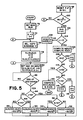
- FIG. 5 is a flow chart of a program for microcomputer 22 of FIG. 1 for measuring VH and VL, for computing Vo(X,Y) and G(X,Y) for each combination of capacitor 2, and current source 1-9 and for the combinations of capacitors 1 and 3 and current source 5, and for computing Gc(X) for capacitors 1-3.
- the microcomputer sets multiplexers 18 and 19 of FIG. 1 to select the charac terization signal as the trigger input to comparators 16 and 17 and then (block 76) the microcomputer sets capacitor index X to indicate capacitor 2, and current source index Y to indicate current source 1.
- the microprocessor (in block 76) next sets the range signal to sweep generator 10 to connect capacitor X and current source Y to the amplifier 24 of FIG. 2.
- the period Pc of the characterization signal is set to the appropriate value Pc(X,Y)
- the VL(X,Y) parameter is set to its nominal value VLO(X,Y) for the combination of capacitor X and current source Y
- a pair of indexes N and J are set to 0.
- the J index is 0 when the microprocessor is currently searching for VL and 1 if it is currently searching for VH.
- the N index is utilized to determine the amount by which the DAC 46 input data is to be increased or decreased after each sweep cycle. Since J is initially 0, the DAC 46 input data is set (block 80) to the current value of VL(X,Y).
- the microprocessor waits (block 82) until the A gate circuit 14 indicates that the sweep has ended twice, thereby ensuring that the DAC 46 input data remained unchanged for a full sweep. Thereafter, (block 84), the microprocessor checks whether the J index is greater than 0, and if not, it checks to see if the Q output of flip-flop 54 is high (block 86). If Q is high, VL(X,Y) is incremented by RV/2 N (block 88) and if Q is low, VL(X,Y) is decremented by RV/2 N (block 90), where RV is the search range described hereinabove.
- the process continues to iterate through the loop formed by blocks 80, 82, 84, 86, 88 (or 90), 98 and 100, until the value of VL(X,Y) has been adjusted in block 88 and/or 90 with the resolution of the DAC 46, at which point RV/2 N is less than 1 (block 100). Thereafter (block 102), the value of N is set to 0 ⁇ , and the value of J is incremented. If J is not greater than 1 (block 104), then the value of VH(X,Y) is set to the nominal, expected, value VHO(X,Y) of the DAC 46 input data for the present combination of capacitor X and current source Y (block 105).
- the microcomputer thereupon returns to block 80 and resets the DAC input data to the initial value of VH(X,Y) and then waits for two end of the sweep signals (block 82). Since J is now greater than 0 ⁇ (block 84), the microcomputer checks the value of the Q output of flip-flop 54 (block 92) and increments VH(X,Y) by RV/2 N if Q is high (block 94), or decrements VH(X,Y) by RV/2 N if Q is low (block 96). Flip-flop 54 is reset and N is incremented in block 98 and, if RV/2 N is not less than 1 (block 100), the microcomputer returns to block 80.
- the microcomputer continues to iterate through the loop formed by blocks 80, 82, 84, 92, 94 (or 96), 98 and 100, until the value of VH(X,Y) has been adjusted in block 94 and/or 96 within the resolution limit of the DAC 46, at which point RV/2 N is less than 1 (block 100). Thereafter (block 102) the value of N is reset to 0 ⁇ and the value of J is incremented to 2. Since J is now greater than 1 (block 104), the microcomputer computes (block 106) the values of Vo(X,Y) and G(X,Y) for the combination of capacitor 2 and current source 1 from the last adjusted values of VL(X,Y) and VH(X,Y) according to the relations described hereinabove.
- Y is incremented by 1 (block 118) and the program returns to block 76 where the range signal to the A sweep generator is set such that capacitor 2 and current source 2 are selected since X and Y each have the value 2.
- the period Pc of the characterization signal is altered and the VL(X,Y) parameter is set to a new initial value to suit the new combination of capacitor X and current source Y, and the N and J indexes are reinitialized.
- VL(X,Y) and VH(X,Y) measurement process is repeated and Vo(X,Y) and G(X,Y) are computed for the combination of capacitor 1 and current source 5 (block 106). Since X is 1, block 108 directs the program through block 110 where X is set to 3 and Y is set to 5, and then back to block 76 where capacitor 3 and current source 5 are selected. The iterative measurement process is repeated once more, with the values of Vo(X,Y) and G(X,Y) being computed (block 106) for capacitor 3 and current source 5.
- block 112 leads to block 120 where the values of Gc(1), Gc(2), and Gc(3) are computed according to the previously described relationships based on the measured values of Vo(X,Y) and G(X,Y) computed in block 106. The measurement process thereupon ends.
- an oscilloscope computes the delay time between the start of a sweep signal and a selected point along a displayed waveform based on measured sweep gain (G) and sweep start (Vo) parameters characterizing the sweep signal, and on the value of data (D) supplied a DAC which produces an output voltage controlling point selection.
- the sweep start parameter Vo is the value of data applied to the DAC which would cause the DAC to produce an output voltage equal to the actual starting level of the sweep signal
- the sweep gain parameter G indicates the rate of increase in DAC input data required to produce a DAC output signal with the same slew rate as the sweep signal.
- the sweep gain G and sweep start Vo parameters are accurately determined by utilizing a square-wave signal of a known period to trigger the sweep, iteratively adjusting DAC input data, and comparing the sweep signal to the resulting DAC output signal to determine two values VL and VH of DAC input data which produce DAC output voltages matching the sweep signal magnitude at two different pulse edges of the square wave signal. Parameters G and Vo are then computed from VL and VH and the known period of the square-wave signal.
Landscapes
- Physics & Mathematics (AREA)
- General Physics & Mathematics (AREA)
- Tests Of Electronic Circuits (AREA)
- Stabilization Of Oscillater, Synchronisation, Frequency Synthesizers (AREA)
- Testing Electric Properties And Detecting Electric Faults (AREA)
- Measurement Of Resistance Or Impedance (AREA)
Applications Claiming Priority (2)
| Application Number | Priority Date | Filing Date | Title |
|---|---|---|---|
| US06/902,363 US4868465A (en) | 1986-08-29 | 1986-08-29 | Sweep generator error characterization |
| US902363 | 1986-08-29 |
Publications (2)
| Publication Number | Publication Date |
|---|---|
| EP0257726A2 true EP0257726A2 (de) | 1988-03-02 |
| EP0257726A3 EP0257726A3 (de) | 1989-12-06 |
Family
ID=25415760
Family Applications (1)
| Application Number | Title | Priority Date | Filing Date |
|---|---|---|---|
| EP87301946A Withdrawn EP0257726A3 (de) | 1986-08-29 | 1987-03-06 | Prüfung der Fehlereigenschaft eines Kippgenerators |
Country Status (4)
| Country | Link |
|---|---|
| US (1) | US4868465A (de) |
| EP (1) | EP0257726A3 (de) |
| JP (1) | JPS6363973A (de) |
| CA (1) | CA1271857A (de) |
Cited By (1)
| Publication number | Priority date | Publication date | Assignee | Title |
|---|---|---|---|---|
| EP0472238A1 (de) * | 1990-08-20 | 1992-02-26 | Fluke Corporation | Messgerät und Zeitbasisschaltung zur Anwendung in einem derartigen Messgerät |
Families Citing this family (4)
| Publication number | Priority date | Publication date | Assignee | Title |
|---|---|---|---|---|
| US4916677A (en) * | 1989-06-19 | 1990-04-10 | Tektronix, Inc. | Automatic period and frequency measurements |
| US5005145A (en) * | 1989-06-19 | 1991-04-02 | Tektronix, Inc. | Method and apparatus for calibrating a scan convertor |
| US5184062A (en) * | 1990-05-11 | 1993-02-02 | Nicolet Instrument Corporation | Dynamically calibrated trigger for oscilloscopes |
| US5212485A (en) * | 1990-09-27 | 1993-05-18 | Tektronix, Inc. | Analog oscilloscope digitizer |
Family Cites Families (6)
| Publication number | Priority date | Publication date | Assignee | Title |
|---|---|---|---|---|
| US4007400A (en) * | 1975-03-11 | 1977-02-08 | Sutton John F | Deflection system for cathode ray oscilloscope |
| JPS6020704B2 (ja) * | 1976-01-27 | 1985-05-23 | テクトロニツクス・インコ−ポレイテツド | デジタル測定装置 |
| US4097798A (en) * | 1977-02-28 | 1978-06-27 | Tektronix, Inc. | Oscilloscope sweep rate indicator system |
| US4121164A (en) * | 1977-04-27 | 1978-10-17 | Tektronix, Inc. | Automatic trigger circuit |
| US4581585A (en) * | 1983-02-07 | 1986-04-08 | Tektronix, Inc. | Apparatus and method for automatically calibrating a sweep waveform generator |
| US4647915A (en) * | 1984-10-29 | 1987-03-03 | Tektronix, Inc. | Method and apparatus for adjusting displayed oscilloscope parameters |
-
1986
- 1986-08-29 US US06/902,363 patent/US4868465A/en not_active Expired - Fee Related
-
1987
- 1987-02-26 CA CA000530687A patent/CA1271857A/en not_active Expired - Fee Related
- 1987-03-06 EP EP87301946A patent/EP0257726A3/de not_active Withdrawn
- 1987-08-17 JP JP62203956A patent/JPS6363973A/ja active Pending
Cited By (1)
| Publication number | Priority date | Publication date | Assignee | Title |
|---|---|---|---|---|
| EP0472238A1 (de) * | 1990-08-20 | 1992-02-26 | Fluke Corporation | Messgerät und Zeitbasisschaltung zur Anwendung in einem derartigen Messgerät |
Also Published As
| Publication number | Publication date |
|---|---|
| EP0257726A3 (de) | 1989-12-06 |
| CA1271857A (en) | 1990-07-17 |
| JPS6363973A (ja) | 1988-03-22 |
| US4868465A (en) | 1989-09-19 |
Similar Documents
| Publication | Publication Date | Title |
|---|---|---|
| US4162531A (en) | Method and apparatus for programmable and remote numeric control and calibration of electronic instrumentation | |
| EP0244052B1 (de) | Programmierbare Abtastablenkschaltung | |
| US4581585A (en) | Apparatus and method for automatically calibrating a sweep waveform generator | |
| US4099240A (en) | Method and apparatus for programmable and remote numeric control and calibration of electronic instrumentation | |
| US5068614A (en) | Swept frequency domain relectometry enhancement | |
| US6864833B2 (en) | Time-base generator with self-compensating control loop | |
| US4608657A (en) | Method and apparatus for testing probe calibration | |
| EP0257726A2 (de) | Prüfung der Fehlereigenschaft eines Kippgenerators | |
| US5016202A (en) | Interpolated swept parameter system for synthesized sweeper | |
| US4855968A (en) | Time interval measurement system for analog oscilloscope | |
| JPH02305025A (ja) | 電圧制御発振器の出力周波数を直線化するための制御回路および方法 | |
| US4628254A (en) | Method for digitally measuring waveforms | |
| US4143318A (en) | Wide range digital meter | |
| JP3148225B2 (ja) | ディジタル同期掃引方法 | |
| JPH0666665B2 (ja) | 傾斜信号校正方法及びデジタル・タイム・ベース回路 | |
| US4097798A (en) | Oscilloscope sweep rate indicator system | |
| CA1185720A (en) | Precision time tracking line generator | |
| US4916677A (en) | Automatic period and frequency measurements | |
| US2634604A (en) | Combined torsiograph and torsiograph calibration device | |
| JPH077015B2 (ja) | 傾斜波形発生器用自動校正装置 | |
| US4277747A (en) | Wide range digital meter | |
| US5410245A (en) | Method and apparatus for calibrating electronic scales for the horizontal axis | |
| US4999573A (en) | Method and apparatus for measurement gate display | |
| JP2561461B2 (ja) | 周波数掃引信号発生器 | |
| JPH0149904B2 (de) |
Legal Events
| Date | Code | Title | Description |
|---|---|---|---|
| PUAI | Public reference made under article 153(3) epc to a published international application that has entered the european phase |
Free format text: ORIGINAL CODE: 0009012 |
|
| AK | Designated contracting states |
Kind code of ref document: A2 Designated state(s): DE FR GB NL |
|
| PUAL | Search report despatched |
Free format text: ORIGINAL CODE: 0009013 |
|
| AK | Designated contracting states |
Kind code of ref document: A3 Designated state(s): DE FR GB NL |
|
| 17P | Request for examination filed |
Effective date: 19900320 |
|
| 17Q | First examination report despatched |
Effective date: 19920122 |
|
| STAA | Information on the status of an ep patent application or granted ep patent |
Free format text: STATUS: THE APPLICATION IS DEEMED TO BE WITHDRAWN |
|
| 18D | Application deemed to be withdrawn |
Effective date: 19930421 |
|
| RIN1 | Information on inventor provided before grant (corrected) |
Inventor name: FOX, HENRY GREGORY Inventor name: STEVENS, DOUGLAS CLIFFORD |