EP0257461A2 - Method and apparatus for the manufacture of spirally wound tubes, bobbins, containers or the like - Google Patents
Method and apparatus for the manufacture of spirally wound tubes, bobbins, containers or the like Download PDFInfo
- Publication number
- EP0257461A2 EP0257461A2 EP87111717A EP87111717A EP0257461A2 EP 0257461 A2 EP0257461 A2 EP 0257461A2 EP 87111717 A EP87111717 A EP 87111717A EP 87111717 A EP87111717 A EP 87111717A EP 0257461 A2 EP0257461 A2 EP 0257461A2
- Authority
- EP
- European Patent Office
- Prior art keywords
- thread
- wound
- tube
- core
- bundle
- Prior art date
- Legal status (The legal status is an assumption and is not a legal conclusion. Google has not performed a legal analysis and makes no representation as to the accuracy of the status listed.)
- Granted
Links
Images


Classifications
-
- B—PERFORMING OPERATIONS; TRANSPORTING
- B31—MAKING ARTICLES OF PAPER, CARDBOARD OR MATERIAL WORKED IN A MANNER ANALOGOUS TO PAPER; WORKING PAPER, CARDBOARD OR MATERIAL WORKED IN A MANNER ANALOGOUS TO PAPER
- B31C—MAKING WOUND ARTICLES, e.g. WOUND TUBES, OF PAPER, CARDBOARD OR MATERIAL WORKED IN A MANNER ANALOGOUS TO PAPER
- B31C3/00—Making tubes or pipes by feeding obliquely to the winding mandrel centre line
-
- B—PERFORMING OPERATIONS; TRANSPORTING
- B29—WORKING OF PLASTICS; WORKING OF SUBSTANCES IN A PLASTIC STATE IN GENERAL
- B29C—SHAPING OR JOINING OF PLASTICS; SHAPING OF MATERIAL IN A PLASTIC STATE, NOT OTHERWISE PROVIDED FOR; AFTER-TREATMENT OF THE SHAPED PRODUCTS, e.g. REPAIRING
- B29C53/00—Shaping by bending, folding, twisting, straightening or flattening; Apparatus therefor
- B29C53/56—Winding and joining, e.g. winding spirally
- B29C53/58—Winding and joining, e.g. winding spirally helically
- B29C53/60—Winding and joining, e.g. winding spirally helically using internal forming surfaces, e.g. mandrels
- B29C53/62—Winding and joining, e.g. winding spirally helically using internal forming surfaces, e.g. mandrels rotatable about the winding axis
- B29C53/66—Winding and joining, e.g. winding spirally helically using internal forming surfaces, e.g. mandrels rotatable about the winding axis with axially movable winding feed member, e.g. lathe type winding
- B29C53/665—Coordinating the movements of the winding feed member and the mandrel
-
- B—PERFORMING OPERATIONS; TRANSPORTING
- B29—WORKING OF PLASTICS; WORKING OF SUBSTANCES IN A PLASTIC STATE IN GENERAL
- B29C—SHAPING OR JOINING OF PLASTICS; SHAPING OF MATERIAL IN A PLASTIC STATE, NOT OTHERWISE PROVIDED FOR; AFTER-TREATMENT OF THE SHAPED PRODUCTS, e.g. REPAIRING
- B29C53/00—Shaping by bending, folding, twisting, straightening or flattening; Apparatus therefor
- B29C53/80—Component parts, details or accessories; Auxiliary operations
- B29C53/8008—Component parts, details or accessories; Auxiliary operations specially adapted for winding and joining
- B29C53/8016—Storing, feeding or applying winding materials, e.g. reels, thread guides, tensioners
-
- B—PERFORMING OPERATIONS; TRANSPORTING
- B65—CONVEYING; PACKING; STORING; HANDLING THIN OR FILAMENTARY MATERIAL
- B65H—HANDLING THIN OR FILAMENTARY MATERIAL, e.g. SHEETS, WEBS, CABLES
- B65H75/00—Storing webs, tapes, or filamentary material, e.g. on reels
- B65H75/02—Cores, formers, supports, or holders for coiled, wound, or folded material, e.g. reels, spindles, bobbins, cop tubes, cans, mandrels or chucks
- B65H75/04—Kinds or types
- B65H75/08—Kinds or types of circular or polygonal cross-section
- B65H75/10—Kinds or types of circular or polygonal cross-section without flanges, e.g. cop tubes
-
- B—PERFORMING OPERATIONS; TRANSPORTING
- B65—CONVEYING; PACKING; STORING; HANDLING THIN OR FILAMENTARY MATERIAL
- B65H—HANDLING THIN OR FILAMENTARY MATERIAL, e.g. SHEETS, WEBS, CABLES
- B65H2701/00—Handled material; Storage means
- B65H2701/30—Handled filamentary material
- B65H2701/31—Textiles threads or artificial strands of filaments
Definitions
- tubes which are produced by spirally (helically) winding cardboard or paper strips onto a mandrel are reinforced by one or two layers of likewise spirally wound metal wires or strips.
- the spirally wound pipe is formed as an endless pipe and is cut to the lengths in which it is needed as a container, pipe or the like.
- US Pat. No. 3,350,030 describes bobbins for winding yarns, threads or the like, which have a plurality of layers of glass fiber strands over a core made of a resin-impregnated paper pulp.
- the larger part of the glass fiber strands should have a small pitch angle in order to absorb radial forces, while a smaller part of the strands should have a high pitch angle in order to compensate for stress occurring along the sleeve axis.
- the present invention has set itself the task of disadvantages of the known manufacturing method for spiral wound tubes, from which by cutting z. B. containers or sleeves are made and which have a reinforcing insert made of thread-like structures to avoid, in particular to enable continuous production of such tubes.
- this is done by continuously winding at least two sheets of thread-like structures - hereinafter referred to as thread sheets - onto the cardboard or paper core, which have a changing pitch angle over time - and because of the forward movement of the core also spatially on this - with at least each Thread layer of a thread sheet on the tube core has a very small pitch angle, that is, the threads are approximately perpendicular to the tube axis.
- threads lie close together; rather, z. B. in the case of multifilament polyester threads, a thread spacing of approx. 1 mm, to give the tube or the container or the spinning sleeve produced therefrom sufficient strength.
- the number of threads in a thread sheet depends on the distance between the threads and on the width of the thread sheet, which should correspond to the paper web width to be processed. The threads should be so far apart that the paper web lying under the thread sheet with the paper web lying thereon is guaranteed. It is also possible to arrange only one layer of thread between two layers of paper.
- a further paper layer is then usually applied over the thread layer, in particular again by spiral winding of a paper strip. This is conveniently done in the same operation as winding the tube core and forming the thread layers, so that an endless, thread-reinforced tube is created in one operation.
- This tube can be in the z. B. for spinning sleeves, containers or the like. Necessary lengths are cut.
- the device for carrying out the method according to the invention has - in addition to the devices known for the production of spiral-wound tubes - at least two thread guides arranged parallel to the winding mandrel and displaceable in the axial direction thereof for each thread group.
- the movement of these thread guides parallel to the winding mandrel is carried out by control devices; as control devices such.
- B. cam discs are used, which are driven in particular synchronously with the rotation of the sleeve core and thus the forward movement of the core.
- Fig. 1 shows the cut and flat-laid tube core 1 with three sets of threads 2a, 2b and 2c wound thereon, with only two threads being drawn from each set of threads during one revolution of the tube core for the sake of clarity.
- the duration of the working cycle of each thread guide corresponds to one revolution of the tube core.
- Each thread guide and thus each thread sheet moves parallel to the tube core at its feed rate during half of a working cycle.
- the thread guide member runs back into the starting position, as a result of which the thread position in question comes to lie obliquely to the axial direction of the tube.
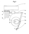
- 3 and 4 show the devices essential for the device according to the invention, the devices provided for the individual thread groups 2a, 2b and 2c each being designated with the same letter as the thread group in question.
- the holders 4 for the thread guides 5 are fastened to the guide rod 6 by means of supports 3. This is displaceable in the bearing 7 by the back and forth movement of the traversing rod 9, which through the joint 8 with the guide rod 6 and through the joint 8 'with the Housing is connected.
- the movement of the traversing rod 9 is generated by a cam plate 11 and sliding block 10, the shape of the cam plate 11 determining the placement angle of the thread sheet 2 on the tube core 1.
- the cam 11 is driven via the servomotor 14, which runs synchronously with the drive of the winding machine (not shown), via the gear 13 by means of the axis 12.
Landscapes
- Engineering & Computer Science (AREA)
- Mechanical Engineering (AREA)
- Making Paper Articles (AREA)
Abstract
Description
Nach US-PS 1 312 780 werden Rohre, die durch spiraliges (schraubenförmiges) Wickeln von Papp- oder Papierstreifen auf einen Dorn hergestellt werden, durch eine oder zwei Lagen von ebenfalls spiralig aufgewickelten Metalldrähten oder -streifen verstärkt. Das spiralig gewickelte Rohr entsteht als endloses Rohr und wird in die Längen geschnitten, in denen es als Behälter, Leitung oder dergl. benötigt wird.According to US Pat. No. 1,312,780, tubes which are produced by spirally (helically) winding cardboard or paper strips onto a mandrel are reinforced by one or two layers of likewise spirally wound metal wires or strips. The spirally wound pipe is formed as an endless pipe and is cut to the lengths in which it is needed as a container, pipe or the like.
US-PS 3 350 030 beschreibt Spulhülsen zum Aufwickeln von Garnen, Fäden oder dergl., die über einem Kern aus einer harzgetränkten Papiermasse mehrere Lagen von Glasfasersträngen aufweisen. Hierbei soll der größere Teil der Glasfaserstränge einen geringen Steigungswinkel aufweisen, um Radialkräfte aufzunehmen, während ein kleinerer Teil der Stränge hohe Steigungswinkel aufweisen soll, um längs der Hülsenachse auftretende Beanspruchung zu kompensieren.US Pat. No. 3,350,030 describes bobbins for winding yarns, threads or the like, which have a plurality of layers of glass fiber strands over a core made of a resin-impregnated paper pulp. Here, the larger part of the glass fiber strands should have a small pitch angle in order to absorb radial forces, while a smaller part of the strands should have a high pitch angle in order to compensate for stress occurring along the sleeve axis.
Die Herstellung derartiger Rohre bzw. Spulhülsen im kontinuierlichen Wickelvorgang ist nicht möglich. Wegen der stetigen Dreh- und Vorwärtsbewegung des Rohrkernes kann eine Fadenschar jeweils nur für eine begrenzte Zeit und damit nur für eine begrenzte Länge unter einem vorgegebenen Steigungswinkel auf den Rohrkern aufgebracht werden, wenn dieser Winkel von dem durch Dreh- und Vorschubgeschwindigkeit bestimmten Winkel abweicht. US-PS 3 350 030 schlägt daher vor, den Rohrkern nicht im kontinuierlichen, sondern im absatzweisen Verfahren mit den Glasfasersträngen und der darüber anzubringenden Papierlage zu versehen und anschließend das Rohr auf die gewünschte Spulhülsenlänge abzuschneiden. Diese Arbeitsweise ist aufwendig und führt zu Abfall an den Enden der Rohrstücke, auf die die Glasfaser-Wicklungen aufgebracht werden.It is not possible to manufacture such tubes or winding tubes in a continuous winding process. Because of the constant rotation and forward movement of the tube core, a group of threads can only be applied to the tube core for a limited time and thus only for a limited length at a predetermined pitch angle if this angle deviates from the angle determined by the speed of rotation and feed. US Pat. No. 3,350,030 therefore proposes not to provide the tube core with the glass fiber strands and the paper layer to be attached in a continuous, but in a batch process, and then to cut the tube to the desired winding tube length. This method of operation is complex and leads to waste at the ends of the pipe sections to which the glass fiber windings are applied.
Die vorliegende Erfindung hat es sich zur Aufgabe gestellt, Nachteile der bekannten Herstellungsverfahren für spiralgewickelte Rohre, aus denen durch Zerschneiden z. B. Behälter oder Hülsen hergestellt werden und die eine Verstärkungseinlage aus fadenförmigen Gebilden aufweisen, zu vermeiden, insbesondere eine kontinuierliche Herstellung derartiger Rohre zu ermöglichen. Erfindungsgemäß geschieht dies dadurch, daß kontinuierlich auf den Papp- oder Papierkern mindestens zwei Scharen aus fadenförmigen Gebilden - im folgenden kurz Fadenschar - aufgewickelt werden, die zeitlich - und wegen der Vorwärtsbewegung des Kerns auch räumlich auf diesem - wechselnde Steigungswinkel besitzen, wobei jeweils mindestens die Fadenlage einer Fadenschar auf dem Rohrkern einen sehr kleinen Steigungswinkel aufweist, die Fäden also etwa senkrecht zur Rohrachse liegen. Insbesondere wird dies dadurch ermöglicht, daß die Führungsorgane jeder Fadenschar parallel zur Rohrachse verschiebbar sind, und das Führungsorgan für die Fadenschar, die senkrecht zur Rohrachse aufgewickelt werden soll, parallel zu dieser etwa mit der gleichen Geschwindigkeit wie der Vorschub des Rohres bewegt wird.The present invention has set itself the task of disadvantages of the known manufacturing method for spiral wound tubes, from which by cutting z. B. containers or sleeves are made and which have a reinforcing insert made of thread-like structures to avoid, in particular to enable continuous production of such tubes. According to the invention, this is done by continuously winding at least two sheets of thread-like structures - hereinafter referred to as thread sheets - onto the cardboard or paper core, which have a changing pitch angle over time - and because of the forward movement of the core also spatially on this - with at least each Thread layer of a thread sheet on the tube core has a very small pitch angle, that is, the threads are approximately perpendicular to the tube axis. In particular, this is made possible by the fact that the guide members of each thread group are displaceable parallel to the tube axis, and the guide element for the thread sheet, which is to be wound up perpendicular to the tube axis, is moved parallel to this at approximately the same speed as the advance of the tube.
Neben den in den US-PSen 1 312 780 und 3 350 030 genannten Metalldrähten und -streifen bzw. Glasfasersträngen können als fadenförmige Gebilde alle Arten von Garnen, sekundär gesponnen aus natürlichen und mineralischen sowie aus Chemiefasern, Filamentgarne, Drähte und Bändchen aus zellulosischen und synthetischen Produkten aber auch Metallfilamentgarne sowie Filamentgarne aus Glas und Stein Verwendung finden. Bevorzugt werden fadenförmige Gebilde aus Thermoplasten wie Polyamiden, Polyolefinen und insbesondere Polyester, vor allem in Form von monofilen oder multifilen Filamentfäden oder von Bändchen.In addition to the metal wires and strips or glass fiber strands mentioned in US Pat. Nos. 1,312,780 and 3,350,030, all types of yarns, spun from natural and mineral fibers, as well as from chemical fibers, filament yarns, wires and tapes made of cellulosic and synthetic fibers, can be used as thread-like structures Products but also metal filament yarns and filament yarns made of glass and stone are used. Thread-like structures made of thermoplastics such as polyamides, polyolefins and in particular polyester are preferred, especially in the form of monofilament or multifilament filament threads or tapes.
Es ist nicht erforderlich, daß die Fäden dicht bei dicht liegen; vielmehr reicht z. B. bei multifilen Polyesterfäden ein Fadenabstand von ca. 1 mm aus, dem Rohr bzw. dem daraus hergestellten Behälter bzw. der Spinnhülse eine ausreichende Festigkeit zu verleihen. Die Anzahl der Fäden einer Fadenschar richtet sich nach dem Abstand der Fäden untereinander sowie nach der Breite der Fadenschar, die der zu verarbeitenden Papierbahnbreite entsprechen sollte. Die Fäden sollten so weit voneinander entfernt liegen, daß ein Verkleben der unter der Fadenschar liegenden Papierbahn mit der darauf liegenden Papierbahn gewährleistet ist. Auch ist es möglich, jeweils nur eine Fadenlage zwischen zwei Papierlagen anzuordnen.It is not necessary that the threads lie close together; rather, z. B. in the case of multifilament polyester threads, a thread spacing of approx. 1 mm, to give the tube or the container or the spinning sleeve produced therefrom sufficient strength. The number of threads in a thread sheet depends on the distance between the threads and on the width of the thread sheet, which should correspond to the paper web width to be processed. The threads should be so far apart that the paper web lying under the thread sheet with the paper web lying thereon is guaranteed. It is also possible to arrange only one layer of thread between two layers of paper.
Über die Fadenlage wird üblicherweise anschließend eine weitere Papierschicht angebracht, insbesondere wiederum durch spiraliges Wickeln eines Papierstreifens. Dies geschieht zweckmäßig im gleichen Arbeitsgang wie das Wickeln des Rohrkernes und die Bildung der Fadenlagen, so daß ein endloses, fadenverstärktes Rohr in einem Arbeitsgang entsteht. Dieses Rohr kann in die z. B. für Spinnhülsen, Behälter oder dergl. notwendigen Längen geschnitten werden.A further paper layer is then usually applied over the thread layer, in particular again by spiral winding of a paper strip. This is conveniently done in the same operation as winding the tube core and forming the thread layers, so that an endless, thread-reinforced tube is created in one operation. This tube can be in the z. B. for spinning sleeves, containers or the like. Necessary lengths are cut.
Die Vorrichtung zur Durchführung des erfindungsgemäßen Verfahrens besitzt - neben den für die Herstellung spiralgewickelter Rohre bekannten Einrichtungen - mindestens zwei parallel zum Wickeldorn angeordnete und in dessen Achsrichtung verschiebbare Fadenführer für jeweils eine Fadenschar. Die Bewegung dieser Fadenführer parallel zum Wickeldorn wird durch Steuereinrichtungen besorgt; als Steuereinrichtungen können z. B. Kurvenscheiben verwendet werden, die insbesondere synchron mit der Drehung des Hülsenkernes und damit der Vorwärtsbewegung des Kernes angetrieben werden.The device for carrying out the method according to the invention has - in addition to the devices known for the production of spiral-wound tubes - at least two thread guides arranged parallel to the winding mandrel and displaceable in the axial direction thereof for each thread group. The movement of these thread guides parallel to the winding mandrel is carried out by control devices; as control devices such. B. cam discs are used, which are driven in particular synchronously with the rotation of the sleeve core and thus the forward movement of the core.
In der anliegenden Zeichnung ist die Erfindung weiter erläutert. Fig. 1 zeigt den aufgeschnittenen und plangelegten Rohrkern 1 mit darauf gewickelten drei Fadenscharen 2a, 2b und 2c, wobei wegen der Übersichtlichkeit von jeder Fadenschar nur zwei Fäden während einer Umdrehung des Rohrkernes gezeichnet sind. Die Dauer des Arbeitszyklus jedes Fadenführers entspricht einer Umdrehung des Rohrkernes. Jeder Fadenführer und damit jede Fadenschar bewegt sich jeweils während der Hälfte eines Arbeitszyklus parallel zum Rohrkern mit dessen Vorschubgeschwindigkeit. Jeweils während der zweiten Hälfte des Arbeitszyklus läuft das Fadenführungsorgan zurück in die Ausgangsstellung, wodurch die betreffende Fadenlage schräg zur Achsrichtung des Rohres zu liegen kommt.The invention is further explained in the accompanying drawing. Fig. 1 shows the cut and flat-
In der Fig. 2 ist in gleicher Weise eine parallel zur Achsrichtung des Rohres aufgeschnittene Rohrlage 1 dargestellt, auf der drei Fadenscharen 2a, 2b und 2c aufgewickelt worden sind.2 shows in the same way a
In den Fig. 3 und 4 sind die für die erfindungsgemäße Vorrichtung wesentlichen Einrichtungen dargestellt, wobei die für die einzelnen Fadenscharen 2a, 2b und 2c vorgesehenen Vorrichtungen jeweils mit dem gleichen Buchstaben bezeichnet sind wie die betreffende Fadenschar. Die Halter 4 für die Fadenführer 5 sind mittels Träger 3 an der Führungsstange 6 befestigt. Diese ist im Lager 7 verschiebbar durch die Hin- und Herbewegung der Changierstange 9, die durch das Gelenk 8 mit der Führungsstange 6 und durch das Gelenk 8' mit dem Gehäuse verbunden ist. Die Bewegung der Changierstange 9 wird durch eine Kurvenscheibe 11 und Kulissenstein 10 erzeugt, wobei die Form der Kurvenscheibe 11 die Ablegewinkel der Fadenschar 2 auf dem Rohrkern 1 bestimmt. Der Antrieb der Kurvenscheibe 11 erfolgt über den Stellmotor 14, der mit dem Antrieb der nicht gezeigten Wickelmaschine synchron läuft, über das Getriebe 13 mittels Achse 12.3 and 4 show the devices essential for the device according to the invention, the devices provided for the
Claims (5)
Applications Claiming Priority (2)
| Application Number | Priority Date | Filing Date | Title |
|---|---|---|---|
| DE19863627839 DE3627839A1 (en) | 1986-08-16 | 1986-08-16 | METHOD AND DEVICE FOR PRODUCING SPIRAL WINDED PIPES, SLEEVES, CONTAINERS OR THE LIKE |
| DE3627839 | 1986-08-16 |
Publications (3)
| Publication Number | Publication Date |
|---|---|
| EP0257461A2 true EP0257461A2 (en) | 1988-03-02 |
| EP0257461A3 EP0257461A3 (en) | 1989-12-06 |
| EP0257461B1 EP0257461B1 (en) | 1992-02-26 |
Family
ID=6307545
Family Applications (1)
| Application Number | Title | Priority Date | Filing Date |
|---|---|---|---|
| EP87111717A Expired - Lifetime EP0257461B1 (en) | 1986-08-16 | 1987-08-13 | Method and apparatus for the manufacture of spirally wound tubes, bobbins, containers or the like |
Country Status (2)
| Country | Link |
|---|---|
| EP (1) | EP0257461B1 (en) |
| DE (2) | DE3627839A1 (en) |
Citations (4)
| Publication number | Priority date | Publication date | Assignee | Title |
|---|---|---|---|---|
| US1312780A (en) * | 1917-12-06 | 1919-08-12 | William B Fenn | Reinforced receptacle, tube, or the like and process of making the same. |
| US3350030A (en) * | 1965-10-20 | 1967-10-31 | Nvf Company | Fiberglass reinforced textile bobbin |
| DE2303661A1 (en) * | 1972-02-04 | 1973-08-09 | Vera Fabrikker As | METHOD AND DEVICE FOR FEEDING REINFORCING FEMS IN THE PRODUCTION OF PIPES FROM REINFORCED DUROPLAST |
| US4010054A (en) * | 1971-05-03 | 1977-03-01 | Albert L. Jeffers | Thermoplastic filament winding process |
-
1986
- 1986-08-16 DE DE19863627839 patent/DE3627839A1/en not_active Withdrawn
-
1987
- 1987-08-13 EP EP87111717A patent/EP0257461B1/en not_active Expired - Lifetime
- 1987-08-13 DE DE8787111717T patent/DE3776839D1/en not_active Expired - Fee Related
Patent Citations (4)
| Publication number | Priority date | Publication date | Assignee | Title |
|---|---|---|---|---|
| US1312780A (en) * | 1917-12-06 | 1919-08-12 | William B Fenn | Reinforced receptacle, tube, or the like and process of making the same. |
| US3350030A (en) * | 1965-10-20 | 1967-10-31 | Nvf Company | Fiberglass reinforced textile bobbin |
| US4010054A (en) * | 1971-05-03 | 1977-03-01 | Albert L. Jeffers | Thermoplastic filament winding process |
| DE2303661A1 (en) * | 1972-02-04 | 1973-08-09 | Vera Fabrikker As | METHOD AND DEVICE FOR FEEDING REINFORCING FEMS IN THE PRODUCTION OF PIPES FROM REINFORCED DUROPLAST |
Also Published As
| Publication number | Publication date |
|---|---|
| DE3627839A1 (en) | 1988-02-18 |
| DE3776839D1 (en) | 1992-04-02 |
| EP0257461A3 (en) | 1989-12-06 |
| EP0257461B1 (en) | 1992-02-26 |
Similar Documents
| Publication | Publication Date | Title |
|---|---|---|
| DE2818575C3 (en) | Method and device for the production of cable elements with optical fibers | |
| CH625459A5 (en) | ||
| EP0003279B1 (en) | Method and apparatus for sz twisting in layers of cable elements around a flexible core | |
| DE2923132A1 (en) | A METHOD FOR MANUFACTURING A LONG DISTURBED THREAD FOR AN OPTICAL CABLE, AN OPTICAL CABLE, AND A LONG DRAWN THREAD FOR AN OPTICAL CABLE | |
| DE102008060788A1 (en) | Thread spool winding method, involves winding thread with single side shortened lifting stroke for producing marking layer at one of set of front surfaces during cross winding of thread, where thread is guided in and out within stroke | |
| EP0498171B1 (en) | Method and apparatus for producing a yarn by the centrifugal spinning method | |
| DE2938902A1 (en) | DEVICE FOR THE PRODUCTION OF SHORT CHAINS, ESPECIALLY FOR FABRIC PATTERNS IN THE COLORFUL FABRIC | |
| EP3431428B1 (en) | Method and device for winding a spinning thread, in particular a glass yarn in order to form a bobbin | |
| WO1999024344A1 (en) | Method and device for spooling a continuously running thread | |
| DE2017011A1 (en) | Method and device for the production of optical monofilament fiber ribbons for coherent fiber scopes | |
| EP1758807A1 (en) | Method and device for winding a thread bobbin | |
| EP0820542B1 (en) | Installation for producing at least one knitted ribbon including crocheted rubber threads | |
| DE4424468C2 (en) | Device for winding a thread reserve on a twisting machine | |
| DE3004375A1 (en) | METHOD AND DEVICE FOR PRODUCING METAL STRINGS, IN PARTICULAR STRINGS FOR REINFORCING OBJECTS FROM ELASTOMERIC MATERIAL | |
| EP0257461B1 (en) | Method and apparatus for the manufacture of spirally wound tubes, bobbins, containers or the like | |
| DE102018008486A1 (en) | Workstation of a double twisting machine or cabling machine for the production of carpet yarn | |
| DE3045713C2 (en) | Method and apparatus for manufacturing an optical cable | |
| DE3206636A1 (en) | DEVICE FOR PRODUCING METAL STRINGS | |
| DE102012219578B4 (en) | Fiber laying machine for simultaneous laying and sewing of multiple fiber strands | |
| AT414236B (en) | Production of wound film strips on bobbins, comprises cutting extruded film into strips, with sub-group to be split into fibrils, before all being drawn together for bobbin winding | |
| DE102005020369B3 (en) | Device and method for winding fibers onto a movable mandrel | |
| DE2602488A1 (en) | High speed polymeric yarn winding machine - has bobbins provided with one oblique radial face in which is formed yarn catcher to protect latter | |
| EP1566474A2 (en) | Air jet texturing machine | |
| AT394467B (en) | Method and apparatus for fitting a flexible metallic screen (shield) consisting of individual wires around a cable core | |
| DE3345010A1 (en) | Device for winding components from fibre-reinforced plastic |
Legal Events
| Date | Code | Title | Description |
|---|---|---|---|
| PUAI | Public reference made under article 153(3) epc to a published international application that has entered the european phase |
Free format text: ORIGINAL CODE: 0009012 |
|
| 17P | Request for examination filed |
Effective date: 19870828 |
|
| AK | Designated contracting states |
Kind code of ref document: A2 Designated state(s): BE CH DE FR GB IT LI LU NL |
|
| PUAL | Search report despatched |
Free format text: ORIGINAL CODE: 0009013 |
|
| AK | Designated contracting states |
Kind code of ref document: A3 Designated state(s): BE CH DE FR GB IT LI LU NL |
|
| 17Q | First examination report despatched |
Effective date: 19910219 |
|
| GRAA | (expected) grant |
Free format text: ORIGINAL CODE: 0009210 |
|
| AK | Designated contracting states |
Kind code of ref document: B1 Designated state(s): BE CH DE FR GB IT LI LU NL |
|
| ITF | It: translation for a ep patent filed |
Owner name: ING. A. GIAMBROCONO & C. S.R.L. |
|
| GBT | Gb: translation of ep patent filed (gb section 77(6)(a)/1977) | ||
| REF | Corresponds to: |
Ref document number: 3776839 Country of ref document: DE Date of ref document: 19920402 |
|
| ET | Fr: translation filed | ||
| PLBE | No opposition filed within time limit |
Free format text: ORIGINAL CODE: 0009261 |
|
| STAA | Information on the status of an ep patent application or granted ep patent |
Free format text: STATUS: NO OPPOSITION FILED WITHIN TIME LIMIT |
|
| 26N | No opposition filed | ||
| PGFP | Annual fee paid to national office [announced via postgrant information from national office to epo] |
Ref country code: GB Payment date: 19930805 Year of fee payment: 7 |
|
| PGFP | Annual fee paid to national office [announced via postgrant information from national office to epo] |
Ref country code: FR Payment date: 19930817 Year of fee payment: 7 |
|
| PGFP | Annual fee paid to national office [announced via postgrant information from national office to epo] |
Ref country code: CH Payment date: 19930820 Year of fee payment: 7 |
|
| PGFP | Annual fee paid to national office [announced via postgrant information from national office to epo] |
Ref country code: LU Payment date: 19930825 Year of fee payment: 7 |
|
| PGFP | Annual fee paid to national office [announced via postgrant information from national office to epo] |
Ref country code: NL Payment date: 19930831 Year of fee payment: 7 |
|
| PGFP | Annual fee paid to national office [announced via postgrant information from national office to epo] |
Ref country code: BE Payment date: 19930909 Year of fee payment: 7 |
|
| PGFP | Annual fee paid to national office [announced via postgrant information from national office to epo] |
Ref country code: DE Payment date: 19931020 Year of fee payment: 7 |
|
| EPTA | Lu: last paid annual fee | ||
| PG25 | Lapsed in a contracting state [announced via postgrant information from national office to epo] |
Ref country code: LU Free format text: LAPSE BECAUSE OF NON-PAYMENT OF DUE FEES Effective date: 19940813 Ref country code: GB Effective date: 19940813 |
|
| PG25 | Lapsed in a contracting state [announced via postgrant information from national office to epo] |
Ref country code: LI Effective date: 19940831 Ref country code: CH Effective date: 19940831 Ref country code: BE Effective date: 19940831 |
|
| BERE | Be: lapsed |
Owner name: NORDDEUTSCHE FASERWERKE G.M.B.H. Effective date: 19940831 |
|
| PG25 | Lapsed in a contracting state [announced via postgrant information from national office to epo] |
Ref country code: NL Effective date: 19950301 |
|
| GBPC | Gb: european patent ceased through non-payment of renewal fee |
Effective date: 19940813 |
|
| NLV4 | Nl: lapsed or anulled due to non-payment of the annual fee | ||
| PG25 | Lapsed in a contracting state [announced via postgrant information from national office to epo] |
Ref country code: FR Effective date: 19950428 |
|
| REG | Reference to a national code |
Ref country code: CH Ref legal event code: PL |
|
| PG25 | Lapsed in a contracting state [announced via postgrant information from national office to epo] |
Ref country code: DE Effective date: 19950503 |
|
| REG | Reference to a national code |
Ref country code: FR Ref legal event code: ST |
|
| PG25 | Lapsed in a contracting state [announced via postgrant information from national office to epo] |
Ref country code: IT Free format text: LAPSE BECAUSE OF NON-PAYMENT OF DUE FEES;WARNING: LAPSES OF ITALIAN PATENTS WITH EFFECTIVE DATE BEFORE 2007 MAY HAVE OCCURRED AT ANY TIME BEFORE 2007. THE CORRECT EFFECTIVE DATE MAY BE DIFFERENT FROM THE ONE RECORDED. Effective date: 20050813 |