EP0257455A1 - Sealing head for use in a hydraulic tube testing apparatus - Google Patents
Sealing head for use in a hydraulic tube testing apparatus Download PDFInfo
- Publication number
- EP0257455A1 EP0257455A1 EP87111684A EP87111684A EP0257455A1 EP 0257455 A1 EP0257455 A1 EP 0257455A1 EP 87111684 A EP87111684 A EP 87111684A EP 87111684 A EP87111684 A EP 87111684A EP 0257455 A1 EP0257455 A1 EP 0257455A1
- Authority
- EP
- European Patent Office
- Prior art keywords
- sectors
- tube
- bore
- head
- chamber
- Prior art date
- Legal status (The legal status is an assumption and is not a legal conclusion. Google has not performed a legal analysis and makes no representation as to the accuracy of the status listed.)
- Granted
Links
Images


Classifications
-
- G—PHYSICS
- G01—MEASURING; TESTING
- G01M—TESTING STATIC OR DYNAMIC BALANCE OF MACHINES OR STRUCTURES; TESTING OF STRUCTURES OR APPARATUS, NOT OTHERWISE PROVIDED FOR
- G01M3/00—Investigating fluid-tightness of structures
- G01M3/02—Investigating fluid-tightness of structures by using fluid or vacuum
- G01M3/022—Test plugs for closing off the end of a pipe
Definitions
- the present invention relates to a closure head for a hydraulic test bench for tubes.
- Tubes intended mainly for the petroleum industry or for transporting fluids are generally tested, before delivery to users, at high pressures which create stresses in the tubes close to the elastic limit.
- the tube is placed on a bench which has at each end of the tube a sealing head which covers the end of the tube while ensuring its tightness.
- One of the shutter heads is supplied with water to test the tube.
- the structure of the bench makes it possible to withstand the significant thrusts induced by the hydraulic test pressure exerted on the closed surface at each end.
- the invention relates to a closure head for a hydraulic test bench for tubes, comprising a head body comprising a first bore into which one end of a tube can be freely introduced, a second bore of diameter greater than that the first bore at the bottom of which an elastic seal is introduced, means for supplying a pressurized fluid into a chamber formed between the outer periphery of the seal and said second bore allowing its contraction against said tube, said seal being axially immobilized from the opposite side to the end of the tube by an annular series of independent support sectors of said seal, said sectors comprising sliding control means allowing their clamping against the tube as well as their spacing, said sectors comprising axial retaining means of the opposite side of said joint.
- a shutter head thus formed is known from documents US-A-4537407 and FR-A-2571494 (For the United States: US-A-4537407).
- the seal is not very accessible and requires for its replacement a disassembly of a plurality of parts and of all the sectors separately.
- the object of the present invention is to propose a shutter head allowing extremely easy and quick replacement of the seal. It also aims to ensure better storage of the joint while not leaving any passage gap and finally to have only one command for tightening and loosening of the support sectors.
- the invention thus relates to a shutter head as defined above and characterized in that the axial retaining means of the support sectors comprise a packing press fixed on said head body, a friction plate being in contact with the packing press and comprising a circular peripheral rim engaging, in a position separated from the support sectors, in a groove produced at the periphery of said support sectors.
- said sectors partially overlap and an anti-extrusion ring of wedge-shaped section is arranged adjusted in said second bore between the joint and said support sectors.
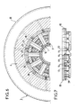
- FIG. 1 we therefore see a tube 1 which must be tested for tightness and which, to do this, is subjected to a high hydraulic pressure test.
- each end of the tube is capped by a closure head 2 comprising a sealing system applying to the outer periphery of the tube.
- the hydraulic pressure is sent into the tube in the direction of arrow F by the bottom of the shutter head situated on the left in FIG. 1, the bottom of the shutter head on the right being obviously blocked, for example by a shutter 3. Pressure could also be sent from both ends.
- the two shutter heads 2 are obviously integral with a test bench frame, not shown, making it possible to separate and bring together one shutter head relative to the other and to withstand the forces of significant axial thrusts. undergone by the shutter heads during the tests.
- a closure head 2 according to the invention comprises a head body 4 pierced with a first bore 5 and the bottom of which is closed by a screwed shutter 3 provided with a seal 6.
- a screwed shutter 3 provided with a seal 6.
- Inside the bore 5 is introduced one end of the tube 1 to be tested.
- the tube 1 is provided at one of its ends, during its hydraulic test, with its coupling sleeve 7 with another tube and it is around this sleeve 7 that the seal must be made between the sleeve and the closure head 2.
- the test is generally carried out without a coupling sleeve and therefore the seal is made directly between the tube 1 and the shutter head 2.
- the tube is therefore introduced into the bore 5 until it stops against stop pieces 8, 9.
- An elastic seal 10 the cross section of which has a vague L shape, is introduced into the bottom of a second bore 11 formed in the head body 4. This bore has a diameter greater than that of the first bore 5.
- the inner diameter of the seal 10 is equal to or greater than the diameter of the first bore 5 so that the tube 1 can be inserted without risk of damage to the attached.
- the seal 10 On the end of the tube side, the seal 10 is immobilized axially against the bottom 12 of the second bore 11 and on the opposite side, it bears against an annular series of support sectors 13 independent of the seal 10 and partially overlapping .
- These sectors in the retracted rest position as shown in FIG. 3, can come to tighten against the tube (the sleeve 7 in the box of the example described) by tightening radially and circumferentially, the parts overlapping, sliding them one against the others increasing their covering surface (decreasing it when they move away from the tube).
- the support sectors 13 In FIGS. 4 and 5, the support sectors 13 are in the contracted position against the sleeve 7.
- Figure 10 shows in perspective two of these sectors 13 in a relative position corresponding to maximum tightening. It can be seen that the overlapping parts are in abutment against one another.
- An anti-extrusion ring 17 whose section is wedge-shaped (triangle, isosceles rectangle) is also introduced in an adjusted manner in the second bore 11, between the elastic seal 10 and the support sectors 13. This anti-extrusion ring prevents the radial extrusion of the joint. It also has grooves corresponding to the advanced parts 14 of the support sectors 13 thus allowing their radial sliding.
- the seal 10 also includes complementary grooves of these advanced parts 14 for covering the support sectors.
- FIG. 8 makes it possible to better appreciate the shape and the arrangement of the different parts.
- the sectors 13 and the seal 10 are shown in the contracted position, pressed against the sleeve 7, therefore corresponding to the position shown in FIG. 5.
- the support sectors 13 are retained axially by a packing press 18 screwed into the head body 5.
- a friction plate 19 is fixed by screws such as 50 to the packing press 18.
- the support sectuers 13 slide, during their movement against this friction plate 19.
- the friction plate 19 has a circular peripheral rim 20 which, in the position separated from the support sectors 13 (FIG. 3), engages in a groove 21 (FIG. 4, 5) produced at the outer periphery of the sectors of support.
- This arrangement allows rapid disassembly of all of the support sectors 13 for, for example, changing the seal 10. It suffices for this, no tube 1 being placed on the test bench and the shutter head being in the rest position, sectors separated, joint at rest, to place a dismounting sleeve 51 by fixing it to the packing press 18 by screws such as 52 and to unscrew the packing press 18 which drives with it in rotation and axial translation the friction plate 19, the rim 20 of which turns inside the grooves 21 of the bearing sectors by pulling them axially.
- the support sectors are immobile in rotation because of the grooves 15 in which the parts 14 of the sectors penetrate, and also because of the operating rods 22 of the support sectors 13 whose end 23 penetrates into a T-groove 24 practiced in the common 13 sectors as can be seen in FIG. 10.
- the socket 51 prevents the sectors 13 from falling and can also be used, by giving an appropriate shape to its end, as a tool for dismantling the packing press 18.
- Figure 11 shows the device being dismantled while the support sectors 13 are already cleared from the ends 23 of the operating rods 22.
- the packing press 18 has blind holes such as 25 allowing the introduction of dismounting lugs .
- the support sectors 13 are maneuvered by means of rods 22 which each have, for this purpose at their outer end, a plate 26.
- the small plates 26 all bear, inwards, against two toric chambers 27 and 28 in elastomer surrounding the head body 4 and outside, surrounding all the plates 26, is arranged another toric chamber 29 in elastomer.
- the assembly is contained in a casing 30 fixed to the head body 4.
- FIG. 23 shows the hydraulic control diagram which will now be described at the same time as the operation of the device with further reference to Figures 3 , 4 and 5.
- a pump 31 driven by a motor 32 draws water from a tank 33 and the discharge into the toric chamber 29 by means of a solenoid valve 34 excited so as to make the connection of the four pipes 35 to 38 as shown by the arrows on the left of the solenoid valve, thus connecting 35 to 38 and 37 to 36.
- the support sectors 13 therefore come into abutment against the sleeve 7.
- the solenoid valve 39 is exited so as to supply the annular chamber 40 surrounding the seal 10.
- a channel 41 is drilled in the head body 4 which connects the chamber 40 to a pipe 42 connected to the outlet of the solenoid valve 39 by means of a non-return valve 43.
- the seal 10 deforms and the assembly is in the position shown entered in FIG. 4 where the sectors 13 close the annular space between the sleeve 7 and the shutter head and where the lip 44 of seal 10 comes into contact with the sleeve ensuring pre-sealing.
- the tube When this pre-sealing pressure is reached in the chamber 40, the tube is filled with water for the sealing test and the test pressure is increased, for example up to 1500 bars.
- a valve 45 located in a pipe 46 connecting the interior of the tube to the pipe 42, is opened and puts the interior of the tube into communication. and the chamber 40, the pressure of which then rises simultaneously with that existing outside the tube.
- Figure 5 shows the final position during the test.
- the water is decompressed simultaneously in the tube and in the chamber 40, the valve 45 remaining open.
- the seal 10 returns to its initial shape by itself as shown in FIG. 3.
- the support sectors 13 are loosened by exciting the solenoid valve 37 so as to make the connection between the conduits 36, 38 and 35, 37 in accordance with right figurative arrows.
- the solenoid valve 39 is closed so as not to supply the chamber 40.
Abstract
Description
La présente invention concerne une tête d'obturation pour banc d'épreuve hydraulique de tubes.The present invention relates to a closure head for a hydraulic test bench for tubes.
Les tubes destinés principalement à l'industrie pétrolière ou au transport de fluides sont généralement éprouvés, avant livraison aux utilisateurs, à des pressions importantes qui créent dans les tubes des contraintes voisines de la limite élastique.Tubes intended mainly for the petroleum industry or for transporting fluids are generally tested, before delivery to users, at high pressures which create stresses in the tubes close to the elastic limit.
Pour réaliser cette épreuve hydraulique, le tube est placé sur un banc qui comporte à chaque extrémité du tube une tête d'obturation venant coiffer l'extrémité du tube en assurant son étanchéité.To carry out this hydraulic test, the tube is placed on a bench which has at each end of the tube a sealing head which covers the end of the tube while ensuring its tightness.
L'une des têtes d'obturation est alimentée en eau pour la mise à l'épreuve du tube. La structure du banc permet de tenir les poussées importantes induites par la pression hydraulique d'épreuve s'exerçant sur la surface obturée à chaque extrémité.One of the shutter heads is supplied with water to test the tube. The structure of the bench makes it possible to withstand the significant thrusts induced by the hydraulic test pressure exerted on the closed surface at each end.
Ainsi, l'invention concerne une tête d'obturation pour banc d'épreuve hydraulique de tubes comprenant un corps de tête comportant un premier alésage dans lequel peut s'introduire librement une extrémité d'un tube, un deuxième alésage de diamètre supérieur à celui du premier alésage au fond duquel est introduit un joint élastique, des moyens d'amenée d'un fluide sous pression dans une chambre constituée entre la périphérie extérieure du joint et ledit second alésage permettant sa contraction contre ledit tube, ledit joint étant axialment immobilisé du côté opposé à l'extrémité du tube par une série annulaire de secteurs d'appui indépendants dudit joint, lesdits secteurs comportant des moyens de commande de coulissement permettant leur serrage contre le tube ainsi que leur écartement, lesdits secteurs comportant des moyens de retenue axiale du côté opposé audit joint.Thus, the invention relates to a closure head for a hydraulic test bench for tubes, comprising a head body comprising a first bore into which one end of a tube can be freely introduced, a second bore of diameter greater than that the first bore at the bottom of which an elastic seal is introduced, means for supplying a pressurized fluid into a chamber formed between the outer periphery of the seal and said second bore allowing its contraction against said tube, said seal being axially immobilized from the opposite side to the end of the tube by an annular series of independent support sectors of said seal, said sectors comprising sliding control means allowing their clamping against the tube as well as their spacing, said sectors comprising axial retaining means of the opposite side of said joint.
Une tête d'obturation ainsi constituée est connue par les documents US-A-4537407 et FR-A-2571494 (Pour les Etats-Unis : US-A-4537407).A shutter head thus formed is known from documents US-A-4537407 and FR-A-2571494 (For the United States: US-A-4537407).
Cependant le joint d'étanchéité est peu accessible et requiert pour son remplacement un démontage d'une pluralité de pièces et de tous les secteurs séparément.However, the seal is not very accessible and requires for its replacement a disassembly of a plurality of parts and of all the sectors separately.
La présent invention a pour but de proposer une tête d'obturation permettant un remplacement extrêmement facile et rapide du joint d'étanchéité. Elle a également pour but d'assurer un meilleur emmagasinement du joint en ne laissant aucun interstice de passage et enfin de n'avoir qu'une commande unique pour le serrage et le desserage des secteurs d'appui.The object of the present invention is to propose a shutter head allowing extremely easy and quick replacement of the seal. It also aims to ensure better storage of the joint while not leaving any passage gap and finally to have only one command for tightening and loosening of the support sectors.
L'invention a ainsi pour objet une tête d'obturation telle que définit ci-dessus et caractérisée en ce que les moyens de retenue axiale des secteurs d'appui comportent un presse garniture fixé sur ledit corps de tête, une plaque de frottement étant en contact avec le presse garniture et comportant un rebord périphérique circulaire s'engageant, en position écartée des secteurs d'appui, dans une gorge réalisée à la périphérie desdits secteurs d'appui.The invention thus relates to a shutter head as defined above and characterized in that the axial retaining means of the support sectors comprise a packing press fixed on said head body, a friction plate being in contact with the packing press and comprising a circular peripheral rim engaging, in a position separated from the support sectors, in a groove produced at the periphery of said support sectors.
Selon une autre caractéristique, lesdits secteurs se recouvrent partiellement et un anneau anti-extrusion de section en forme de coin est disposé ajusté dans ledit second alésage entre le joint et lesdits secteurs d'appui.According to another characteristic, said sectors partially overlap and an anti-extrusion ring of wedge-shaped section is arranged adjusted in said second bore between the joint and said support sectors.
L'invention sera mieux comprise à la lumière de la description d'un exemple de mise en oeuvre de l'invention faite ci-après en référence au dessin annexé dans lequel :
- La figure 1 est une représention schématique montrant un tube à essayer muni à chacune de ses extrémités d'une tête d'obturation selon l'invention.
- La figure 2 montre schématiquement une tête d'obturation selon l'invention avec son circuit de commande hydraulique.
- La figure 3 montre en demi-coupe axiale une tête d'obturation selon l'invention dans sa position de repos c'est-à-dire joint non serré.
- La figure 4 est une vue similaire à celle de la figure 3 mais dans une position intermédiaire entre la position de repos et la position étanche de fonctionnement.
- La figure 5 représente la tête d'obturation dans sa position étanche de fonctionnement, joint serré.
- La figure 6 est une coupe selon VI-VI de la figure 5.
- La figure 7 est une vue partielle montrant en vue de dessus par rapport à la figure 6, uniquement les secteurs d'appui, dans leur posi tion resserrée, et la plaque de frottement partiellement coupée.
- La figure 8 est une vue partielle en perspective permettant de mieux voir la forme de certaines pièces.
- La figure 9 est une demi-vue montrant uniquement les secteurs d'appui serrés autour du tube et les tiges de manoeuvre. En traits interrompus mixtes, les secteurs sont montrés en position écartée.
- La figure 10 montre en perspective deux secteurs d'appui.
- La figure 11 montre la tête d'obturation selon l'invention dans une position en cours de démontage des secteurs d'appui.
- Figure 1 is a schematic representation showing a test tube provided at each of its ends with a closure head according to the invention.
- Figure 2 schematically shows a shutter head according to the invention with its hydraulic control circuit.
- FIG. 3 shows in axial half-section a shutter head according to the invention in its rest position, that is to say an unsealed joint.
- Figure 4 is a view similar to that of Figure 3 but in an intermediate position between the rest position and the sealed operating position.
- Figure 5 shows the shutter head in its sealed operating position, tight seal.
- Figure 6 is a section on VI-VI of Figure 5.
- Figure 7 is a partial view showing in top view relative to Figure 6, only the support sectors, in their posi tightened, and the friction plate partially cut.
- Figure 8 is a partial perspective view to better see the shape of some parts.
- Figure 9 is a half view showing only the support sectors tight around the tube and the operating rods. In broken dashed lines, the sectors are shown in the separated position.
- Figure 10 shows in perspective two support sectors.
- Figure 11 shows the shutter head according to the invention in a position during disassembly of the support sectors.
Sur la figure 1 on voit donc un tube 1 dont on doit tester l'étanchéité et qui, pour ce faire, est soumis à une épreuve de haute pression hydraulique. Pour cela, chaque extrémité du tube est coiffée par une tête d'obturation 2 comportant un système d'étanchéité s'appliquant sur le pourtour extérieur du tube. La pression hydraulique est envoyée dans le tube dans le sens de la flèche F par le fond de la tête d'obturation située à gauche sur la figure 1, le fond de la tête d'obturation de droite étant évidemment bouchée, par exemple par un obturateur 3. On pourrait également envoyer la pression par les deux extrémités.In Figure 1 we therefore see a tube 1 which must be tested for tightness and which, to do this, is subjected to a high hydraulic pressure test. For this, each end of the tube is capped by a
Dans l'exemple de réalisation décrit, on a représenté sur les figures suivantes une tête d'obturation dont le fond est bouché par un obturateur 3. On suppose donc que le fluide hydraulique est introduit uniquement par le fond de la tête d'obturation située à l'autre extrémité du tube.In the embodiment described, there is shown in the following figures a shutter head whose bottom is blocked by a
Les deux têtes d'obturation 2 sont évidemment solidaires d'un bâti de banc d'épreuve, non représenté, permettant d'écarter et de rapprocher une tête d'obturation par rapport à l'autre et de supporter les efforts de poussées axiales importantes subies par les têtes d'obturation lors des essais.The two
En se référant aux figure 3 à 11, une tête d'obturation 2 selon l'invention comprend un corps de tête 4 perçé d'un permier alésage 5 et dont le fond est fermé par un obturateur vissé 3 muni d'un joint 6. A l'intérieur de l'alésage 5 est introduit une extrémité du tube 1 à tester. Généralement, comme c'est le cas dans l'exemple décrit, le tube 1 est muni à l'une de ses extrémités, lors de son essai hydraulique, de son manchon d'accouplement 7 avec un autre tube et c'est autour de ce manchon 7 que doit être réalisé l'étanchéité entre le manchon et la tête d'obturation 2. A l'autre extrémité du tube, l'essai se fait généralement sans manchon d'accouplement et donc l'étanchéité est réalisée directement entre le tube 1 et la tête d'obturation 2.Referring to FIGS. 3 to 11, a
Le tube est donc introduit dans l'alésage 5 jusqu'en butée contre des pièces de butée 8, 9.The tube is therefore introduced into the bore 5 until it stops against
Un joint élastique 10, dont la section a une vague forme de L est introduit dans le fond d'un deuxième alésage 11 pratiqué dans le corps de tête 4. Cet alésage a un diamètre supérieur à celui du premier alésage 5.An
Dans la position de repos du joint 10, telle que représentée sur la figure 3, le diamètre intérieur du joint 10 est égal ou supérieur au diamètre du premier alésage 5 de telle sorte que le tube 1, puisse être introduit sans risque d'endommagement du joint.In the rest position of the
Du côté de l'extrémité du tube, le joint 10 est immobilisé axialement contre le fond 12 du deuxième alésage 11 et du côté opposé, il est en appui contre une série annulaire de secteurs d'appui 13 indépendants du joint 10 et se recouvrant partiellement. Ces secteurs, en position de repos rétractés comme représenté sur la figure 3, peuvent venir se serrer contre le tube (le manchon 7 dans le case de l'exemple décrit) en se resserrant radialement et circonférentiellement, les parties se recouvrant, glissant les une contre les autres augmentant leur surface de recouvrement (la diminuant lorsqu'ils s'écartent du tube). Sur les figures 4 et 5, les secteurs d'appui 13 sont en position contractée contre le manchon 7.On the end of the tube side, the
La figure 10 montre en perspective deux de ces secteurs 13 dans une position relative correspondant à un serrage maximal. On voit en effet que les parties en recouvrement sont en butées l'une contre l'autre.Figure 10 shows in perspective two of these
Lors des déplacements des secteurs d'appui 13, ceux-ci sont guidés par leur parties avancées de recouvrement 14 qui coulissent dans des rainures 15 (figure 8) de forme complémentaires, trapézoïdales, pratiquées dans le corps de tête 4. Sur les figures 3, 4, 5, on voit les parties de matière 16 entre ces rainures 15.When the
Un anneau anti-extrusion 17 dont la section est en forme de coin (triangle, rectangle isocèle) est égalment introduit d'une manière adjustée dans le second alésage 11, entre le joint élastique 10 et les secteurs d'appui 13. Cet anneau anti-extrusion évite l'extrusion radiale du joint. Il comporte également des rainures correspondant aux parties avancées 14 des secteurs d'appui 13 permettant ainsi leur coulissement radial.An
De même, le joint 10 comporte également des rainures complémentaires de ces parties avancées 14 de recouvrement des secteurs d'appui.Likewise, the
La perspective de la figure 8 permet de mieux se rendre compte de la forme et de la disposition des différentes pièces. Dans cette perspective, les secteurs 13 ainsi que le joint 10 sont représentés en position contractée, serrée contre le manchon 7, donc correspondant à la position représentée figure 5.The perspective of FIG. 8 makes it possible to better appreciate the shape and the arrangement of the different parts. In this perspective, the
Les secteurs d'appui 13 sont retenus axialement par un presse garniture 18 vissé dans le corps de tête 5. Une plaque de frottement 19 est fixée par des vis telles que 50 au presse garniture 18. Les sectuers d'appui 13 glissent, lors de leur mouvement contre cette plaque de frottement 19.The
La plaque de frottement 19 comporte un rebord périphérique circulaire 20 qui, en position écartée des secteurs d'appui 13 (figure 3), vient s'engager dans une gorge 21 (figure 4, 5) réalisée à la périphérie extérieure des secteurs d'appui. Cette disposition permet le démontage rapide de l'ensemble des secteurs d'appui 13 pour, par exemple, changer le joint 10. Il suffit pour cela, aucun tube 1 n'étant placé sur le banc d'épreuve et la tête d'obturation étant en position de repos, secteurs écartés, joint au repos, de placer une douille de démontage 51 en la fixant au presse garniture 18 par des vis telles que 52 et de dévisser le presse garniture 18 qui entraîne avec lui en rotation et translation axiale la plaque de frottement 19 dont le rebord 20 tourne à l'intérieur des gorges 21 des secteurs d'appui en les tirant axialement. Les secteurs d'appui sont immobiles en rotation à cause des rainures 15 dans lesquelles pénêtrent les parties 14 des secteurs, et à cause aussi des tiges de manoeuvre 22 des secteur d'appui 13 dont l'extrémité 23 pénêtre dans une rainure en T 24 pratiquée dans les secteurs 13 common on le voit bien sur la figure 10. La douille 51 empêche les secteurs 13 de tomber et peut également servir en donnant une forme appropriée à son extrméité, d'outil de démontage du presse garniture 18.The
La figure 11 montre le dispositif en cours de démontage alors que les secteurs d'appui 13 sont déjà dégagés des extrémités 23 des tiges de manoeuvre 22. Le presse garniture 18 comporte des trous borgnes tels que 25 permettant l'introduction d'ergots de démontage.Figure 11 shows the device being dismantled while the
Les secteurs d'appui 13 sont manoeuvrés par l'intermédiaire de tiges 22 qui comportent chacune à cet effet à leur extrémité extérieure, une plaquette 26. Les plauettes 26 s'appuient toutes, vers l'intérieur, contre deux chambres toriques 27 et 28 en élastomère entourant le corps de tête 4 et à l'extérieur, entourant toutes les plaquettes 26, est disposée une autre chambre torique 29 en élastomère. L'ensemble est contenu dans un carter 30 fixé au corps de tête 4.The
La commande de la fermeture des secteurs d'appui 13 s'effectue par la mise sous pression de la chambre torique extérieure 29 et vidange des chambres toriques intérieures 27 et 28. Inversement, l'écartement des secteurs d'appui 13 s'effectue par la mise sous pression des chambres toriques intérieures 27 et 28 et vidage de la chambre torique extérieure 29. La figure 23 montre le schéma hydraulique de commande qui va maintenant être décrit en même temps que le fonctionnement du dispositif en se référant en outre aux figures 3, 4 et 5.The control of the closure of the
Une fois le tube introduit à ses deux extrémités dans les têtes d'obturation, on commence par serrer les secteurs d'appui 13 contre le manchon 7. Pour cela, une pompe 31 entraînée par un moteur 32 aspire de l'eau dans un réservoir 33 et la refoule dans la chambre torique 29 par l'intermédiaire d'une électrovanne 34 excitée de manière à réaliser la liaison des quatres conduites 35 à 38 telle que représentée par les flèches de gauche de l'électrovvane, reliant ainsi 35 à 38 et 37 à 36. Les secteurs d'appui 13 viennnent donc en appui contre le manchon 7. Presque simultanément, on exite l'électrovane 39 de manière à alimenter la chambre annulaire 40 entourant le joint 10. A cet effet, un canal 41 est percé dans le corps de tête 4 qui relie la chambre 40 à une conduite 42 reliée à la sortie d l'électrovanne 39 par l'intermédiaire d'un clapet anti-retour 43. Grâce à cette pression, par exemple de l'ordre de 50 à 100 bars, le joint 10 se déforme et l'ensemble se trouve dans la position représentée sur la figure 4 où les secteurs 13 ferment l'espace annulaire entre le manchon 7 et la tête d'obturation et où la lèvre 44 du joint 10 vient en contact du manchon assurant une pré-étanchéité.Once the tube introduced at its two ends into the closure heads, we begin by tightening the
Lorsque cette pression de pré-étanchéité est atteinte dans la chambre 40 on remplit le tube d'eau pour l'essai d'étanchéité et on monte en pression d'essai, par exemple jusqu'à 1500 bars. Dès que la pression dans le tube atteint la pression de pré-étanchéité existante dans la chambre 40, une vanne 45 située dans une conduite 46 reliant l'intérieur du tube à la conduite 42, est ouverte et met en communication l'intérieur du tube et la chambre 40 dont la pression monte alors simultanément avec celle existante à l'extérieur du tube.When this pre-sealing pressure is reached in the
Sous l'effet de cette très forte pression le joint 10 s'applique fortement et complètement contre le manchon 7 éliminant toute possibilité de fuite de l'eau vers l'extérieur. En outre, le joint 10 étant complètement enfermé n'a aucune possibilité de s'extruder. La figure 5 montre la position finale en cours d'essai.Under the effect of this very high pressure the
Après l'épreuve, la décompression de l'eau s'effectue simultanément dans le tube et dans la chambre 40, la vanne 45 restant ouverte. Le joint 10 reprend de lui-même sa forme initiale comme représentée sur la figure 3. Les secteurs d'appui 13 sont desserrés en excitant l'électrovanne 37 de manière à réaliser la liaison entre les conduites 36, 38 et 35, 37 conformément aux flèches figuratives de droite. Bien entendu, au cours de cette opération l'électrovanne 39 est fermée de manière à ne pas alimenter la chambre 40.After the test, the water is decompressed simultaneously in the tube and in the
Claims (4)
Priority Applications (1)
| Application Number | Priority Date | Filing Date | Title |
|---|---|---|---|
| AT87111684T ATE69648T1 (en) | 1986-08-14 | 1987-08-12 | SEALING BODY FOR PIPE TESTING PRESS USING LIQUID PRESSURE. |
Applications Claiming Priority (2)
| Application Number | Priority Date | Filing Date | Title |
|---|---|---|---|
| FR8611765 | 1986-08-14 | ||
| FR8611765A FR2602866B1 (en) | 1986-08-14 | 1986-08-14 | SHUTTER HEAD FOR HYDRAULIC TUBE TEST BENCH |
Publications (2)
| Publication Number | Publication Date |
|---|---|
| EP0257455A1 true EP0257455A1 (en) | 1988-03-02 |
| EP0257455B1 EP0257455B1 (en) | 1991-11-21 |
Family
ID=9338318
Family Applications (1)
| Application Number | Title | Priority Date | Filing Date |
|---|---|---|---|
| EP87111684A Expired - Lifetime EP0257455B1 (en) | 1986-08-14 | 1987-08-12 | Sealing head for use in a hydraulic tube testing apparatus |
Country Status (6)
| Country | Link |
|---|---|
| US (1) | US4766934A (en) |
| EP (1) | EP0257455B1 (en) |
| JP (1) | JPS6348436A (en) |
| AT (1) | ATE69648T1 (en) |
| DE (1) | DE3774640D1 (en) |
| FR (1) | FR2602866B1 (en) |
Families Citing this family (7)
| Publication number | Priority date | Publication date | Assignee | Title |
|---|---|---|---|---|
| US4909280A (en) * | 1987-05-29 | 1990-03-20 | Instytut Chemii Przemyslowej | Fastener for closing and sealing ends of pipes subjected to internal pressure |
| US5065617A (en) * | 1990-03-08 | 1991-11-19 | Jack W. Hayden | Multiple diameter pipe test end closure |
| US6112578A (en) * | 1999-04-26 | 2000-09-05 | Daimlerchrysler Corporation | Multiple cavity leak test process |
| DE10233358B3 (en) * | 2002-07-23 | 2004-03-18 | Sms Meer Gmbh | Control method for pressure build-up using pressure intensifiers, especially for testing the pressure resistance of pipes |
| DE10356143A1 (en) * | 2003-12-02 | 2005-06-30 | Bosch Rexroth Ag | Hollow-molded body e.g. pipe, interior portion pressurizing device, has hydraulic test circuit pressurizing interior portion of body, and clamping mechanism with test core that is immersed into portion to form inner space in form of ring |
| CN101922992B (en) * | 2010-08-09 | 2012-01-11 | 河北文丰钢铁有限公司 | Continuous casting machine fan-shaped segment roller bed bearing seat detection device |
| US9915582B2 (en) | 2014-10-03 | 2018-03-13 | Offshore Energy Services, Inc. | Modular pressure testing unit |
Citations (5)
| Publication number | Priority date | Publication date | Assignee | Title |
|---|---|---|---|---|
| GB734112A (en) * | 1950-05-06 | 1955-07-27 | Hydropress Inc | Sealing means in particular for machines for testing pipes and like tubular articlesby pressure fluid |
| US4149731A (en) * | 1975-10-06 | 1979-04-17 | Sumitomo Kinzoku Kogyo Kabushiki Kaisha | Packing for use in steel-pipe hydraulic testing apparatus |
| DE3307813C1 (en) * | 1983-03-02 | 1984-08-23 | Mannesmann AG, 4000 Düsseldorf | Tool for testing pipes in a pipe test press |
| FR2564973A1 (en) * | 1984-05-25 | 1985-11-29 | Mannesmann Ag | Tool tests pipes on pipe test press |
| DE3425114A1 (en) * | 1983-03-02 | 1986-01-16 | Mannesmann AG, 4000 Düsseldorf | Sealing tool for test presses |
Family Cites Families (11)
| Publication number | Priority date | Publication date | Assignee | Title |
|---|---|---|---|---|
| NL87924C (en) * | 1953-02-28 | 1900-01-01 | ||
| DE1040818B (en) * | 1956-11-02 | 1958-10-09 | Hugo Gerbener Hydraulik | Device for pressing hollow bodies, in particular pipes |
| DE1114651B (en) * | 1959-03-10 | 1961-10-05 | Schloemann Ag | Test head for pipe test presses |
| FR1237219A (en) * | 1959-06-16 | 1960-07-29 | France Etat | Adjustable nozzle |
| DE1120760B (en) * | 1960-03-05 | 1961-12-28 | Kocks Gmbh Friedrich | Test head for pipe test presses |
| DE1216633B (en) * | 1964-02-29 | 1966-05-12 | Kocks Gmbh Friedrich | Sealing and clamping head for devices for pressing hollow bodies, especially pipes |
| US3803901A (en) * | 1972-10-10 | 1974-04-16 | Taylor Wilson Mfg Co | Pipe tester |
| US4194389A (en) * | 1978-03-20 | 1980-03-25 | Laging Jerry D | Apparatus for pressure testing pipe |
| DE3243201C2 (en) * | 1982-11-23 | 1986-07-03 | Kocks Technik Gmbh & Co, 4010 Hilden | Press for testing pipes |
| US4646561A (en) * | 1984-07-31 | 1987-03-03 | Jack W. Hayden | Method and apparatus for hydrostatic testing of tubular member |
| US4646559A (en) * | 1985-01-22 | 1987-03-03 | Jack W. Hayden | Apparatus and method to test a single connection between a pipe coupling and a single pipe end connected therewith |
-
1986
- 1986-08-14 FR FR8611765A patent/FR2602866B1/en not_active Expired
-
1987
- 1987-08-10 US US07/083,112 patent/US4766934A/en not_active Expired - Fee Related
- 1987-08-11 JP JP62200725A patent/JPS6348436A/en active Granted
- 1987-08-12 AT AT87111684T patent/ATE69648T1/en not_active IP Right Cessation
- 1987-08-12 EP EP87111684A patent/EP0257455B1/en not_active Expired - Lifetime
- 1987-08-12 DE DE8787111684T patent/DE3774640D1/en not_active Expired - Fee Related
Patent Citations (5)
| Publication number | Priority date | Publication date | Assignee | Title |
|---|---|---|---|---|
| GB734112A (en) * | 1950-05-06 | 1955-07-27 | Hydropress Inc | Sealing means in particular for machines for testing pipes and like tubular articlesby pressure fluid |
| US4149731A (en) * | 1975-10-06 | 1979-04-17 | Sumitomo Kinzoku Kogyo Kabushiki Kaisha | Packing for use in steel-pipe hydraulic testing apparatus |
| DE3307813C1 (en) * | 1983-03-02 | 1984-08-23 | Mannesmann AG, 4000 Düsseldorf | Tool for testing pipes in a pipe test press |
| DE3425114A1 (en) * | 1983-03-02 | 1986-01-16 | Mannesmann AG, 4000 Düsseldorf | Sealing tool for test presses |
| FR2564973A1 (en) * | 1984-05-25 | 1985-11-29 | Mannesmann Ag | Tool tests pipes on pipe test press |
Also Published As
| Publication number | Publication date |
|---|---|
| FR2602866A1 (en) | 1988-02-19 |
| FR2602866B1 (en) | 1989-07-28 |
| DE3774640D1 (en) | 1992-01-02 |
| US4766934A (en) | 1988-08-30 |
| EP0257455B1 (en) | 1991-11-21 |
| JPS6348436A (en) | 1988-03-01 |
| JPH0352011B2 (en) | 1991-08-08 |
| ATE69648T1 (en) | 1991-12-15 |
Similar Documents
| Publication | Publication Date | Title |
|---|---|---|
| FR2465149A2 (en) | CONNECTION FOR FLUIDS | |
| FR2717855A1 (en) | Sealing sheath in well, tubing or piping | |
| FR2588325A1 (en) | PRESSURE TANK | |
| FR2504427A1 (en) | TIGHTENING CHUCK WITH HYDRAULICALLY DILATABLE CLAMPING SLEEVE | |
| FR2780751A1 (en) | Process and device for lining a well or channel using inflatable pre formed sections | |
| EP0257455B1 (en) | Sealing head for use in a hydraulic tube testing apparatus | |
| EP2394080A1 (en) | Device for selectively blocking a fluid passage | |
| EP0874947B1 (en) | Core sampling method and core sampler therefor | |
| FR2571459A3 (en) | PNEUMATIC SPRING COMPRISING TWO ELEMENTS CONNECTED BY A FLEXIBLE MEMBRANE IMPERMEABLE TO GASES | |
| FR2547348A1 (en) | WATERPROOF ANCHOR ASSEMBLY | |
| EP0227535B1 (en) | Method and device for withdrawing part of a tube from a heat exchanger | |
| FR2890740A1 (en) | METHOD FOR PRESSING A THREADED COMPONENT | |
| FR2831644A1 (en) | Fluidic connector between two pipes comprises male and female ends, disc shaped valve and sheath able to move relative to tubular bodies delimiting fluid conduits from sealing to opening positions against spring | |
| EP0428433A1 (en) | Device for fixation of upper spider guide plate in a nuclear reactor vessel | |
| FR2579294A1 (en) | Device for repairing pipelines in situ, in particular for drainage channels which cannot be visited | |
| FR2504993A1 (en) | REPAIRABLE PRESSURE TANK | |
| FR2535812A1 (en) | Static leaktightness device and hydraulic test apparatus using such a device | |
| EP0328433B1 (en) | Mechanical seal | |
| WO2023187212A1 (en) | Connection head attachable to an opening of a flanged pipe element for its control under pressure | |
| FR2699646A1 (en) | Flange for the internal casing of pipes to be renovated, as well as device and method provided for this purpose. | |
| FR2498730A1 (en) | Internal obturator for pipe - has cylindrical body surrounded by inflatable element which is expanded into sealing contact with pipe wall | |
| FR2860853A1 (en) | DEVICE FOR CONNECTING A THREADED TUBULAR NOSE TUBE WITH SEAL | |
| CA1297923C (en) | Turning seal joint for pressurized fluid | |
| FR2467657A1 (en) | Sealing jig for pipes being butt welded by electron beam - where jig carries hydraulically inflatable ring seals forced against pipe bores to make vacuum:tight joints | |
| BE402908A (en) |
Legal Events
| Date | Code | Title | Description |
|---|---|---|---|
| PUAI | Public reference made under article 153(3) epc to a published international application that has entered the european phase |
Free format text: ORIGINAL CODE: 0009012 |
|
| AK | Designated contracting states |
Kind code of ref document: A1 Designated state(s): AT DE ES GB |
|
| 17P | Request for examination filed |
Effective date: 19880831 |
|
| RAP1 | Party data changed (applicant data changed or rights of an application transferred) |
Owner name: GEC ALSTHOM SA |
|
| 17Q | First examination report despatched |
Effective date: 19900608 |
|
| GRAA | (expected) grant |
Free format text: ORIGINAL CODE: 0009210 |
|
| AK | Designated contracting states |
Kind code of ref document: B1 Designated state(s): AT DE ES GB |
|
| PG25 | Lapsed in a contracting state [announced via postgrant information from national office to epo] |
Ref country code: GB Effective date: 19911121 Ref country code: AT Effective date: 19911121 |
|
| REF | Corresponds to: |
Ref document number: 69648 Country of ref document: AT Date of ref document: 19911215 Kind code of ref document: T |
|
| REF | Corresponds to: |
Ref document number: 3774640 Country of ref document: DE Date of ref document: 19920102 |
|
| PG25 | Lapsed in a contracting state [announced via postgrant information from national office to epo] |
Ref country code: ES Free format text: LAPSE BECAUSE OF FAILURE TO SUBMIT A TRANSLATION OF THE DESCRIPTION OR TO PAY THE FEE WITHIN THE PRESCRIBED TIME-LIMIT Effective date: 19920304 |
|
| GBV | Gb: ep patent (uk) treated as always having been void in accordance with gb section 77(7)/1977 [no translation filed] | ||
| PLBE | No opposition filed within time limit |
Free format text: ORIGINAL CODE: 0009261 |
|
| STAA | Information on the status of an ep patent application or granted ep patent |
Free format text: STATUS: NO OPPOSITION FILED WITHIN TIME LIMIT |
|
| 26N | No opposition filed | ||
| PG25 | Lapsed in a contracting state [announced via postgrant information from national office to epo] |
Ref country code: DE Effective date: 19930501 |