EP0256495A2 - Befestigungs- und Lösevorrichtung für die Schutzeinrichtung einer Kinderkarre - Google Patents
Befestigungs- und Lösevorrichtung für die Schutzeinrichtung einer Kinderkarre Download PDFInfo
- Publication number
- EP0256495A2 EP0256495A2 EP87111606A EP87111606A EP0256495A2 EP 0256495 A2 EP0256495 A2 EP 0256495A2 EP 87111606 A EP87111606 A EP 87111606A EP 87111606 A EP87111606 A EP 87111606A EP 0256495 A2 EP0256495 A2 EP 0256495A2
- Authority
- EP
- European Patent Office
- Prior art keywords
- fitting
- engagement
- carriage
- holes
- stopper
- Prior art date
- Legal status (The legal status is an assumption and is not a legal conclusion. Google has not performed a legal analysis and makes no representation as to the accuracy of the status listed.)
- Granted
Links
Images


Classifications
-
- B—PERFORMING OPERATIONS; TRANSPORTING
- B62—LAND VEHICLES FOR TRAVELLING OTHERWISE THAN ON RAILS
- B62B—HAND-PROPELLED VEHICLES, e.g. HAND CARTS OR PERAMBULATORS; SLEDGES
- B62B9/00—Accessories or details specially adapted for children's carriages or perambulators
- B62B9/24—Safety guards for children, e.g. harness
- B62B9/245—Removable front guards, e.g. with a tray
-
- Y—GENERAL TAGGING OF NEW TECHNOLOGICAL DEVELOPMENTS; GENERAL TAGGING OF CROSS-SECTIONAL TECHNOLOGIES SPANNING OVER SEVERAL SECTIONS OF THE IPC; TECHNICAL SUBJECTS COVERED BY FORMER USPC CROSS-REFERENCE ART COLLECTIONS [XRACs] AND DIGESTS
- Y10—TECHNICAL SUBJECTS COVERED BY FORMER USPC
- Y10T—TECHNICAL SUBJECTS COVERED BY FORMER US CLASSIFICATION
- Y10T403/00—Joints and connections
- Y10T403/32—Articulated members
- Y10T403/32254—Lockable at fixed position
- Y10T403/32426—Plural distinct positions
- Y10T403/32442—At least one discrete position
- Y10T403/32451—Step-by-step adjustment
- Y10T403/32459—Retainer extends through aligned recesses
-
- Y—GENERAL TAGGING OF NEW TECHNOLOGICAL DEVELOPMENTS; GENERAL TAGGING OF CROSS-SECTIONAL TECHNOLOGIES SPANNING OVER SEVERAL SECTIONS OF THE IPC; TECHNICAL SUBJECTS COVERED BY FORMER USPC CROSS-REFERENCE ART COLLECTIONS [XRACs] AND DIGESTS
- Y10—TECHNICAL SUBJECTS COVERED BY FORMER USPC
- Y10T—TECHNICAL SUBJECTS COVERED BY FORMER US CLASSIFICATION
- Y10T403/00—Joints and connections
- Y10T403/55—Member ends joined by inserted section
- Y10T403/559—Fluted or splined section
-
- Y—GENERAL TAGGING OF NEW TECHNOLOGICAL DEVELOPMENTS; GENERAL TAGGING OF CROSS-SECTIONAL TECHNOLOGIES SPANNING OVER SEVERAL SECTIONS OF THE IPC; TECHNICAL SUBJECTS COVERED BY FORMER USPC CROSS-REFERENCE ART COLLECTIONS [XRACs] AND DIGESTS
- Y10—TECHNICAL SUBJECTS COVERED BY FORMER USPC
- Y10T—TECHNICAL SUBJECTS COVERED BY FORMER US CLASSIFICATION
- Y10T403/00—Joints and connections
- Y10T403/60—Biased catch or latch
- Y10T403/602—Biased catch or latch by separate spring
- Y10T403/604—Radially sliding catch
Definitions
- the present invention relates to a removable guard attachment structure for preventing a baby or an infant from falling from the front of a seat by means of a guard which can be attached to the top ends of armrest bars formed on both sides of the seat in a baby carriage.
- guard mechanisms in baby carriages in which a guard is removably attached so as to be connected between the forward ends of armrest bars disposed on the opposite sides of a seat.
- a baby or an infant seated in the baby carriage can be prevented from falling from the front of the seat.
- a baby can be seated without attaching a guard when the baby has grown to a large size.
- a guard can be attached or removed in accordance with a difference in degree of growth between two or more babies, for example, siblings or other babies when the baby carriage is commonly used for multiple babies or infants.
- the present invention is a guard provided with fitting pipes extending a little from its opposite ends so that the fitting pipes are removably fitted into fitting holes respectively formed in forward ends of armrest bars.
- the fitting pipes are respectively provided with engagement/stopper projections capable of appearing and disappearing so that the stopper projections can be engaged with and disengaged from the fitting holes formed in the armrest bars.
- the guard of the present invention can be removed from the fitting holes of the armrest bars when the guard becomes disused.
- Cover plates having fitting projections extending a little from their rear surfaces are arranged so that the fitting projections are removably fitted into the fitting holes.
- a pair of front leg bars 1, a pair of rear leg bars 2 and a handle bar 3 are foldably coupled and assembled with each other to constitute a body of the baby carriage.
- a pair of armrest bars 4 are provided such that each of them is interposed between a portion of the handle bars 3 near its lower end and the respective upper end pivot portions of both the corresponding front leg bars 1 and the corresponding rear leg bars 2.
- a seat 8 is provided at the inside portion surrounded by the two armrest bars 4.
- Each of the armrest bars 4 has an inverted U-shaped cross section of varying depth so as to be opened downwards.
- a guard 6 is removably attached to the respective forward ends of the armrest bars 4 so as to be interposed therebetween.
- the guard 6 is made of an adequately elastic material, such as formed urethane resin or the like and is U-shaped in plan view. As shown in perspective in Figs. 2 and 5 and in cross section in Figs. 3 and 4, the guard 6 is provided with two fitting pipes 61 extending a little from its opposite ends.
- An engagement/stopper projection 62 is provided in the vicinity of the forward end of each of the fitting pipes 61 so as to be able to appear and disappear.
- Each of the engagement/stopper projections 62 is normally extended out by a U-shaped leaf spring 63 provided at the inside of the corresponding fitting 61 pipe and rigidly connected to the engagement/stopper projection 62.
- the fitting pipes 61 can be designed so as to extend only at the opposite sides of the guard 6. However, in order to make the fitting pipes 61 function as a reinforcing member for increasing the strength of the guard 6, it is preferable that, in place of the separate pipes 61, a single pipe 61 having the same shape as the guard 6 in plan view is used so that the pipe 61 can be installed or embedded in the guard 6 over the entire length of the guard 6.
- Fitting holes 41 are respectively provided in the forward end surfaces of the armrest bars 4 and are of a form so as to be fitted with the fitting pipes 61 of the guard 6. Supports 7 are respectively attached to the back of the fitting holes 41 so as to support the pipes 61 inserted into the fitting holes 41.
- Each of the fitting holes 41 has a notch portion or groove 41 ⁇ formed in its cylindrically formed lower edge so that the fitting hole 41 can be easily fitted with the engagement/stopper projection 62 provided at the forward end of the fitting pipe 61.
- the groove 41 ⁇ may be inclined at its exterior end so as to push the engagement/stopper projections 62 into the fitting pipe 61 as the fitting pipe 61 is inserted into the fitting holes 41.
- Each of the supports 7 is provided with an insertion hole 71 having a size large enough to be fitted with the corresponding fitting pipe 61.
- the insertion hole 71 has an engagement/stopper hole 72 formed at a portion thereof for engagement and stopping the fitting pipe 61 by the engagement/stopper projection 62 provided on the fitting pipe 61.
- Each of the support 7 is constituted by parts other than the constituent parts of the corresponding armrest bar 4 and is fixed to the armrest bar 4.
- Buttons 73 are used for an opening operation so that projections 74 respectively provided at the top ends of the buttons 73 slide along the respective engagement/stopper holes 72.
- the opening operation buttons 73 are respectively accommodated in the front inside portions of the respective armrest bars 4, which are of inverted U-shaped in sectional view, so as to prevent the seated baby or infant from performing a careless opening operation (pushing the buttons).
- Each of the opening operation button 73 are kept in their lower engagement/stopped position while being attached to the upper portion of the support 7 by an elongated belt-like supporting arm 75 extending from the upper side of the button 73. This structure prevents from the button 73 dropping out from the support 7.
- Each of the supporting arms 75 is elastic so that the upper half of the projection 74 is normally placed in the lower half of the engagement/stopper hole 72.
- the opening operation button 73 is housed in the cylindrical opening formed in the lower portion of the support 7 so as to be biased upward against any downward force so that the projection 74 can be prevented from disengaging from the engagement/stopper hole 72.
- the height of the projection 74 is so established that its upper end portion and the upper surface of the support 7 defining the lower surface of insertion hole 71 are the same plane when the projection 74 is pushed up.
- the embodiment has shown the case where the guard 6 is U-shaped in plan view, it is a matter of course that the invention is not limited to the specific embodiment but the form of the guard may be freely modified in accordance with the form of the armrest bars which are respectively engaged with the engagement pipes formed at the end portions of the guard.
- the embodiment has shown the case where the fitting holes 41 are respectively provided in the top ends of the armrest bar 4, it is a matter of course that the invention is not limited thereto but the fitting holes 41 may be respectively provided in the upper portions of the forward ends of the armrest bars 4 or in the inner or outer sides of the armrest bars 4.
- the respective positions of the insertion holes 71, the engagement/stopper holes 72, the opening operation buttons 73, the supporting arms 75, etc., should be modified suitably.
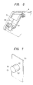
- Cover plates 5 cover the fitting holes 41 respectively provided in the forward end portions of the armrest bars 4 so as to prevent the fitting holes 41 from being exposed.
- Each of the cover plates 5 has a planar shape to be fitted to the forward end surface of the armrest bar 4 and has a fitting projection 51 provided at the center of its rear surface and having a plurality of ribs 52 longitudinally formed on the cylinder portion of the fitting projection 51.
- the form of the fitting projection 51 is not limited by the form of the fitting hole 41 and that also the form of the ribs 52 is not limited to the specifically illustrated embodiment. In short, any form and any structure may be selected as long as the fitting projection 51 can be firmly engaged with the fitting hole 41.
- the cover plates 5 are used only when the guard 6 is not used, such as shown in Fig. 8.
- the cover plates 5 are removed and removably attached to any suitable portion, for example, under the rear surface of a seat board constituting the seat.
- the embodiment has shown the case where the surface of the cover plate is shaped like a plane, it is to be understood that the shape is not limited to the specific embodiment but the surface of the cover plate may be spherically shaped or may be modeled after an animal to provide an interesting design.
- the guard 6 can be easily attached to the armrest bars 4 by such a very simple operation that the fitting pipes 61 formed on the opposite ends of the guard 6 are respectively fitted into the fitting holes 41 provided in the forward end surfaces of the armrest bars 4. Further, the fitting pipes 61 are respectively provided with the engagement/stopper projections 62 respectively formed on the forward ends of the pipes so as to be able to appear and disappear freely, so that the engagement/stopper projections 62 are respectively automatically fitted into the engagement/stopper holes 72 by the insertion of the pipes when the aforementioned fitting operation is made.
- both the engagement/stopper projection 62 are sprung into the engagement/stopper holes 72, so that the pipes 61 are kept in a firmly connected state so as not to be respectively unnecessarily disconnected from the armrest bars 4. Accordingly, safety can be maintained even if a force acts on the body of the baby or infant so as to move the body forwards in the case of a sudden stoppage of the baby carriage.
- the guard 6 can be easily removed from the armrest bars 4 by the following operation if the guard 6 must be removed.
- the projections 74 respectively formed on the forward end portions of the opening operation buttons 73 respectively attached to the upper portion of the supports 7 are pushed upwards from the lower surfaces of the engagement/stopper holes 72 so that the supporting arms 75 supporting the operation button 73 are bent slightly.
- the engagement/stopper projections 67, which are in the state as illustrated in Fig. 3, are respectively pressed by the projections 74 formed on the upper ends of the operation buttons 73.
- the engagement/stopper projections 62 are respectively moved back to the positions where each of the engagement/stopper projections 62 and the surface of corresponding ones of the pipes 61 are in the same place. Accordingly, the guard 6 can be easily removed from the armrest bars 4 by pulling the pipes 61 under this condition. After the guard 6 is removed, the engagement/stopper projections 62 are automatically moved outward by the elastic force of the respective springs 63 in anticipation of the next operation.
- the constitution of the present invention is very simple. Accordingly, not only handling is suitable for those having little knowledge of mechanical operation, but also the guard is excellent in design because the guard can be completely united to the armrest bars 4 when attached.
- the fitting holes 41 respectively provided in the armrest bars 4 to be used for attaching the guard can be respectively easily covered with the cover plates 5 when the guard is not used. Accordingly, not only a good appearance is provided, but also nasty accidents can be prevented from occurring to the baby or infant when his or her fingers are inserted into the fitting holes.
Applications Claiming Priority (4)
| Application Number | Priority Date | Filing Date | Title |
|---|---|---|---|
| JP125712/86U | 1986-08-18 | ||
| JP125713/86U | 1986-08-18 | ||
| JP1986125713U JPH0356142Y2 (de) | 1986-08-18 | 1986-08-18 | |
| JP1986125712U JPH0527336Y2 (de) | 1986-08-18 | 1986-08-18 |
Publications (3)
| Publication Number | Publication Date |
|---|---|
| EP0256495A2 true EP0256495A2 (de) | 1988-02-24 |
| EP0256495A3 EP0256495A3 (en) | 1989-01-18 |
| EP0256495B1 EP0256495B1 (de) | 1990-11-14 |
Family
ID=26462059
Family Applications (1)
| Application Number | Title | Priority Date | Filing Date |
|---|---|---|---|
| EP87111606A Expired - Lifetime EP0256495B1 (de) | 1986-08-18 | 1987-08-11 | Befestigungs- und Lösevorrichtung für die Schutzeinrichtung einer Kinderkarre |
Country Status (5)
| Country | Link |
|---|---|
| US (1) | US5004253A (de) |
| EP (1) | EP0256495B1 (de) |
| CA (1) | CA1313384C (de) |
| DE (1) | DE3766184D1 (de) |
| ES (1) | ES2018511B3 (de) |
Cited By (7)
| Publication number | Priority date | Publication date | Assignee | Title |
|---|---|---|---|---|
| EP0375189A2 (de) * | 1988-12-22 | 1990-06-27 | Britax Restmor Limited | Zusatzgerät für einen Kinderstuhl |
| EP0476565A1 (de) * | 1990-09-17 | 1992-03-25 | Combi Corporation | Kupplungsmechanismus für Schutzbügel eines Kinderwagens |
| US5516142A (en) * | 1993-09-17 | 1996-05-14 | J. G. Hartan Kinderwagenwerk | Buggy with a collapsible frame |
| GB2371274A (en) * | 1998-08-20 | 2002-07-24 | Graco Childrens Prod Inc | Child's stroller with adjustable arm bar |
| WO2007118098A2 (en) * | 2006-04-03 | 2007-10-18 | Graco Children's Products Inc. | Stroller with removable arm bar |
| GB2536526A (en) * | 2015-03-20 | 2016-09-21 | Wonderland Nursery Goods | Stroller |
| KR20210071593A (ko) * | 2019-12-06 | 2021-06-16 | 서운용 | 도어 푸쉬가 가능한 유모차 |
Families Citing this family (12)
| Publication number | Priority date | Publication date | Assignee | Title |
|---|---|---|---|---|
| JPH04154477A (ja) * | 1990-10-16 | 1992-05-27 | Konbi Kk | ベビーカーの折り畳み機構 |
| US5542746A (en) * | 1994-03-17 | 1996-08-06 | Bujaryn; L. Walter | Variable posture component system seating device |
| US5511850A (en) * | 1995-01-03 | 1996-04-30 | Coursey; Jimmy M. | Child's automobile safety seat |
| US5669625A (en) * | 1995-03-29 | 1997-09-23 | Jane, S.A. | Folding child's pushchair |
| US5549311A (en) * | 1995-08-29 | 1996-08-27 | Huang; Li-Chu C. | Armrest and handle assembly for a stroller |
| ES1035128Y (es) * | 1996-07-15 | 1997-08-01 | Jane Sa | Asiento para coches-silla infantiles. |
| DE19543273A1 (de) * | 1995-11-20 | 1997-05-22 | Chen Huang Li Chu | Armauflage- und Handgriffanordnung für einen Kindersportwagen |
| US6976686B2 (en) * | 2001-04-27 | 2005-12-20 | Hsia Ben M | Detachable front guider arrangement of stroller |
| US6478503B1 (en) * | 2001-06-26 | 2002-11-12 | Pao-Hsien Cheng | Locking device for a detachable handrest of a stroller |
| GB2379911B (en) * | 2001-09-25 | 2003-09-10 | Red Lan | Seat device for a stroller |
| US7261381B2 (en) * | 2004-09-15 | 2007-08-28 | Chih-Yi Tsai | Seat with multiple retaining frames |
| CN201665233U (zh) * | 2010-03-24 | 2010-12-08 | 中山市隆成日用制品有限公司 | 婴儿安全座椅扣合机构 |
Citations (4)
| Publication number | Priority date | Publication date | Assignee | Title |
|---|---|---|---|---|
| US2781225A (en) * | 1953-11-30 | 1957-02-12 | American Carry Products Compan | Combination stroller and baby carriage |
| GB993727A (en) * | 1962-11-09 | 1965-06-02 | Rudolph Weiner | Collapsible hand cart |
| EP0027374A2 (de) * | 1979-10-13 | 1981-04-22 | Kassai Kabushiki Kaisha | Kinderwagen |
| US4538830A (en) * | 1982-01-19 | 1985-09-03 | Combi Co., Ltd. | Baby carriage |
Family Cites Families (6)
| Publication number | Priority date | Publication date | Assignee | Title |
|---|---|---|---|---|
| US1152987A (en) * | 1914-06-15 | 1915-09-07 | James F Spalding | Folding extensible stool. |
| US2875815A (en) * | 1957-06-24 | 1959-03-03 | Frank F Taylor Company | Tray construction and latching means therefor |
| US4056115A (en) * | 1976-05-06 | 1977-11-01 | Thomas Morton I | Adapter for manipulating a spring loaded pushbutton |
| JPS5984664A (ja) * | 1982-11-06 | 1984-05-16 | アップリカ葛西株式会社 | 乳母車の開状態ロツク機構 |
| IL73328A (en) * | 1984-10-26 | 1990-02-09 | Tzora Furniture Ind Ltd | Rotatable joint with coaxially assembled parts |
| US4679806A (en) * | 1986-02-19 | 1987-07-14 | Te-Chin Handicraft Enterprise Co., Ltd. | Arm rest and handrail assembly for baby carriage |
-
1987
- 1987-08-04 CA CA000543672A patent/CA1313384C/en not_active Expired - Fee Related
- 1987-08-11 EP EP87111606A patent/EP0256495B1/de not_active Expired - Lifetime
- 1987-08-11 ES ES87111606T patent/ES2018511B3/es not_active Expired - Lifetime
- 1987-08-11 DE DE8787111606T patent/DE3766184D1/de not_active Expired - Lifetime
- 1987-08-14 US US07/085,599 patent/US5004253A/en not_active Expired - Fee Related
Patent Citations (4)
| Publication number | Priority date | Publication date | Assignee | Title |
|---|---|---|---|---|
| US2781225A (en) * | 1953-11-30 | 1957-02-12 | American Carry Products Compan | Combination stroller and baby carriage |
| GB993727A (en) * | 1962-11-09 | 1965-06-02 | Rudolph Weiner | Collapsible hand cart |
| EP0027374A2 (de) * | 1979-10-13 | 1981-04-22 | Kassai Kabushiki Kaisha | Kinderwagen |
| US4538830A (en) * | 1982-01-19 | 1985-09-03 | Combi Co., Ltd. | Baby carriage |
Cited By (11)
| Publication number | Priority date | Publication date | Assignee | Title |
|---|---|---|---|---|
| EP0375189A2 (de) * | 1988-12-22 | 1990-06-27 | Britax Restmor Limited | Zusatzgerät für einen Kinderstuhl |
| EP0375189A3 (en) * | 1988-12-22 | 1990-08-22 | Britax Restmor Limited | Infant chair attachment |
| EP0476565A1 (de) * | 1990-09-17 | 1992-03-25 | Combi Corporation | Kupplungsmechanismus für Schutzbügel eines Kinderwagens |
| US5516142A (en) * | 1993-09-17 | 1996-05-14 | J. G. Hartan Kinderwagenwerk | Buggy with a collapsible frame |
| GB2371274A (en) * | 1998-08-20 | 2002-07-24 | Graco Childrens Prod Inc | Child's stroller with adjustable arm bar |
| GB2371274B (en) * | 1998-08-20 | 2003-01-15 | Graco Childrens Prod Inc | Convertible child care device |
| WO2007118098A2 (en) * | 2006-04-03 | 2007-10-18 | Graco Children's Products Inc. | Stroller with removable arm bar |
| WO2007118098A3 (en) * | 2006-04-03 | 2007-12-13 | Graco Childrens Prod Inc | Stroller with removable arm bar |
| GB2536526A (en) * | 2015-03-20 | 2016-09-21 | Wonderland Nursery Goods | Stroller |
| GB2536526B (en) * | 2015-03-20 | 2020-12-23 | Wonderland Switzerland Ag | Stroller |
| KR20210071593A (ko) * | 2019-12-06 | 2021-06-16 | 서운용 | 도어 푸쉬가 가능한 유모차 |
Also Published As
| Publication number | Publication date |
|---|---|
| EP0256495B1 (de) | 1990-11-14 |
| EP0256495A3 (en) | 1989-01-18 |
| US5004253A (en) | 1991-04-02 |
| DE3766184D1 (de) | 1990-12-20 |
| ES2018511B3 (es) | 1991-04-16 |
| CA1313384C (en) | 1993-02-02 |
Similar Documents
| Publication | Publication Date | Title |
|---|---|---|
| US5004253A (en) | Guard attachment/removal structure in baby carriage | |
| US4805928A (en) | Reclining mechanism of baby carriage | |
| JP4191290B2 (ja) | 幼児キャリヤ取付けシステム | |
| US5203577A (en) | Mechanism for holding seating unit of baby carriage engagement | |
| US5772279A (en) | Coupling system for infant carrier to second support device | |
| US5478135A (en) | Child carrier with detachable base | |
| EP0257588B1 (de) | Klappbarer Kinderwagen | |
| EP1953033B1 (de) | Basis für einen Kindersitz | |
| US4582359A (en) | One-handed high chair tray release mechanism | |
| US5056865A (en) | Shopping cart locking means | |
| EP0483042A1 (de) | Faltbarer Rahmen von Kinderwagen | |
| US20020048488A1 (en) | Attaching articles to bed railings | |
| US6698773B2 (en) | Detachable mounting arrangement for stroller front guard | |
| US5951112A (en) | Seat belt device and a method for stabilizing a seat belt | |
| US5588158A (en) | Bath ring | |
| EP0466489B1 (de) | Höhenverstellbarer Stuhl | |
| TWM577278U (zh) | Children's chair | |
| US20230278471A1 (en) | Infant car seat and stability leg and release actuator | |
| CN215971222U (zh) | 儿童汽车安全座椅座兜和儿童汽车安全座椅 | |
| US5330253A (en) | Mechanism for modulating height of legs of chair for small child | |
| US6910735B2 (en) | Adjustable support structure and method of using the same | |
| KR100603800B1 (ko) | 유아를 업는 기구 | |
| JPH0527336Y2 (de) | ||
| JPS6322936Y2 (de) | ||
| KR200200700Y1 (ko) | 유모차의어린이손잡이착탈구조 |
Legal Events
| Date | Code | Title | Description |
|---|---|---|---|
| PUAI | Public reference made under article 153(3) epc to a published international application that has entered the european phase |
Free format text: ORIGINAL CODE: 0009012 |
|
| AK | Designated contracting states |
Kind code of ref document: A2 Designated state(s): DE ES FR GB IT |
|
| PUAL | Search report despatched |
Free format text: ORIGINAL CODE: 0009013 |
|
| AK | Designated contracting states |
Kind code of ref document: A3 Designated state(s): DE ES FR GB IT |
|
| 17P | Request for examination filed |
Effective date: 19890301 |
|
| 17Q | First examination report despatched |
Effective date: 19890807 |
|
| GRAA | (expected) grant |
Free format text: ORIGINAL CODE: 0009210 |
|
| AK | Designated contracting states |
Kind code of ref document: B1 Designated state(s): DE ES FR GB IT |
|
| ITF | It: translation for a ep patent filed |
Owner name: SOCIETA' ITALIANA BREVETTI S.P.A. |
|
| REF | Corresponds to: |
Ref document number: 3766184 Country of ref document: DE Date of ref document: 19901220 |
|
| ET | Fr: translation filed | ||
| PLBE | No opposition filed within time limit |
Free format text: ORIGINAL CODE: 0009261 |
|
| STAA | Information on the status of an ep patent application or granted ep patent |
Free format text: STATUS: NO OPPOSITION FILED WITHIN TIME LIMIT |
|
| 26N | No opposition filed | ||
| PGFP | Annual fee paid to national office [announced via postgrant information from national office to epo] |
Ref country code: GB Payment date: 19920731 Year of fee payment: 6 |
|
| PGFP | Annual fee paid to national office [announced via postgrant information from national office to epo] |
Ref country code: ES Payment date: 19920826 Year of fee payment: 6 |
|
| PGFP | Annual fee paid to national office [announced via postgrant information from national office to epo] |
Ref country code: FR Payment date: 19920828 Year of fee payment: 6 Ref country code: DE Payment date: 19920828 Year of fee payment: 6 |
|
| PG25 | Lapsed in a contracting state [announced via postgrant information from national office to epo] |
Ref country code: GB Effective date: 19930811 |
|
| PG25 | Lapsed in a contracting state [announced via postgrant information from national office to epo] |
Ref country code: ES Free format text: LAPSE BECAUSE OF THE APPLICANT RENOUNCES Effective date: 19930812 |
|
| GBPC | Gb: european patent ceased through non-payment of renewal fee |
Effective date: 19930811 |
|
| PG25 | Lapsed in a contracting state [announced via postgrant information from national office to epo] |
Ref country code: FR Effective date: 19940429 |
|
| PG25 | Lapsed in a contracting state [announced via postgrant information from national office to epo] |
Ref country code: DE Effective date: 19940503 |
|
| REG | Reference to a national code |
Ref country code: FR Ref legal event code: ST |
|
| REG | Reference to a national code |
Ref country code: ES Ref legal event code: FD2A Effective date: 19991007 |
|
| PG25 | Lapsed in a contracting state [announced via postgrant information from national office to epo] |
Ref country code: IT Free format text: LAPSE BECAUSE OF NON-PAYMENT OF DUE FEES;WARNING: LAPSES OF ITALIAN PATENTS WITH EFFECTIVE DATE BEFORE 2007 MAY HAVE OCCURRED AT ANY TIME BEFORE 2007. THE CORRECT EFFECTIVE DATE MAY BE DIFFERENT FROM THE ONE RECORDED. Effective date: 20050811 |