EP0255884A2 - Clothes display support - Google Patents
Clothes display support Download PDFInfo
- Publication number
- EP0255884A2 EP0255884A2 EP87110271A EP87110271A EP0255884A2 EP 0255884 A2 EP0255884 A2 EP 0255884A2 EP 87110271 A EP87110271 A EP 87110271A EP 87110271 A EP87110271 A EP 87110271A EP 0255884 A2 EP0255884 A2 EP 0255884A2
- Authority
- EP
- European Patent Office
- Prior art keywords
- angle
- clothes
- arm
- clothes display
- cantilever
- Prior art date
- Legal status (The legal status is an assumption and is not a legal conclusion. Google has not performed a legal analysis and makes no representation as to the accuracy of the status listed.)
- Withdrawn
Links
Images
Classifications
-
- A—HUMAN NECESSITIES
- A47—FURNITURE; DOMESTIC ARTICLES OR APPLIANCES; COFFEE MILLS; SPICE MILLS; SUCTION CLEANERS IN GENERAL
- A47F—SPECIAL FURNITURE, FITTINGS, OR ACCESSORIES FOR SHOPS, STOREHOUSES, BARS, RESTAURANTS OR THE LIKE; PAYING COUNTERS
- A47F5/00—Show stands, hangers, or shelves characterised by their constructional features
- A47F5/08—Show stands, hangers, or shelves characterised by their constructional features secured to the wall, ceiling, or the like; Wall-bracket display devices
- A47F5/0807—Display panels, grids or rods used for suspending merchandise or cards supporting articles; Movable brackets therefor
-
- A—HUMAN NECESSITIES
- A47—FURNITURE; DOMESTIC ARTICLES OR APPLIANCES; COFFEE MILLS; SPICE MILLS; SUCTION CLEANERS IN GENERAL
- A47F—SPECIAL FURNITURE, FITTINGS, OR ACCESSORIES FOR SHOPS, STOREHOUSES, BARS, RESTAURANTS OR THE LIKE; PAYING COUNTERS
- A47F5/00—Show stands, hangers, or shelves characterised by their constructional features
- A47F5/08—Show stands, hangers, or shelves characterised by their constructional features secured to the wall, ceiling, or the like; Wall-bracket display devices
-
- A—HUMAN NECESSITIES
- A47—FURNITURE; DOMESTIC ARTICLES OR APPLIANCES; COFFEE MILLS; SPICE MILLS; SUCTION CLEANERS IN GENERAL
- A47F—SPECIAL FURNITURE, FITTINGS, OR ACCESSORIES FOR SHOPS, STOREHOUSES, BARS, RESTAURANTS OR THE LIKE; PAYING COUNTERS
- A47F7/00—Show stands, hangers, or shelves, adapted for particular articles or materials
- A47F7/19—Show stands, hangers, or shelves, adapted for particular articles or materials for garments
- A47F7/24—Clothes racks
Definitions
- This restraint means that the hanging hooks of clothes hangers freely lying on the support rods are given a natural tendency to swing out, which results in a horizontal projection of the clothes hangers at an angle of approximately 60 ° to the longitudinal axis of the support rods and from the arrangement of the support rods themselves a good use of space .
- the inclination of the hangers automatically results in the desired exposure of the exhibits if there is sufficient mobility of two adjacent items of clothing. However, if the garments fit snugly against one another, the resulting liability is sufficient to block a free-running movement. The bran Pieces of the piece must then be moved by hand in order to achieve the desired exposure effect.
- a clothes rack in which the support arms, which preferably protrude radially from a central column, are provided with a plastic covering, which has a comb-shaped support section for receiving the hanging hooks of clothes hangers.
- the comb teeth are at an angle of about 60 ° to the longitudinal axis of the support arm and give the hanging hooks of the hangers a correspondingly forced inclination, so that there is no need to align the hangers.
- the comb-like support section can produce the desired alignment effect on the clothes hangers, but the creation of the plastic cover places a restriction on standard lengths, and the shape of the teeth on the plastic cover is not easy.
- the invention aims to create a clothes display frame according to the preamble of claim 1, in which in particular the advantages of a firmly indexing retaining toothing on the cantilever arms are used, but is also provided with an easily attachable specific toothing.
- the cantilever arms on the frame structure should be designed to be removable, in order to enable optimal use of a given exhibition area.
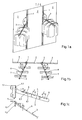
- FIG. 1 a shows a first embodiment of the clothing presentation frame according to the invention, where cantilever arms 3 with a catch arrangement 4 according to FIG .
- Fig. Lb From the plan view of Fig. Lb are the the two cantilever arms 3 shown in the perspective drawing can be seen in their angular relationship with respect to the wall elements 2.
- the cantilever arm on the left is at an acute angle ß 1
- the cantilever on the right is clockwise at an approximately equal angle ß 2 to the wall elements 2.
- the inclination of adjacent brackets can of course be selected uniformly to the left or to the right on the same wall arrangement. Decisive for this is the relative position of a clamping member 5 on the cantilever arm 3, as can be seen from Fig. Lc.
- the cantilever arm 3 having the grid arrangement 4 is attached at an angle ⁇ of approximately 15 °.
- the cantilever arm 3 is at an angle ⁇ of approximately 30 ° to the hook plate and contains V-shaped grooves 6, the lower flank 6.1 of which is approximately at right angles to the cantilever arm extension, while the upper flank 6.2 is inclined upwards at an angle of 35-38 ° is.
- the grooves 6, seen from above are inclined at an angle ⁇ of approximately 60 ° to the cantilever arm 3.
- T-inclination of the grooves 6 can also be chosen to be mirror-symmetrical in order to be able to achieve an opposite inclination of the clothes hangers. See also Fig. 3b.
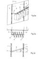
- FIG. 2a shows a second embodiment of the clothes display frame, in which a space partitioning or rear wall arrangement according to FIG. Horizontal brackets 9 are attached to the column members 1, at the front end of which one end of a support rod 10, which takes over the task of a boom arm 3, is fastened with a schematically shown grid arrangement 4 according to FIG. 1c.
- the support rod 10 extends as shown in FIG. 2c and similar to FIG. Lc between the column members 1 at the angle ⁇ of about 15 0 inclined, the inclination can run clockwise or counterclockwise.
- the resulting height difference H in the cantilevers 9 corresponds to an integral multiple of the distance between adjacent indexed suspension points on the column members 1.
- the clothes hangers 8 are inclined at an angle ⁇ to the support bar. This inclination can be left or clockwise if necessary.
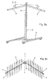
- FIGS. 3a, 3b A one-column embodiment of the clothes display frame can be seen in FIGS. 3a, 3b.
- a standpipe 13 which is arranged on a stationary or mobile foot arrangement 14, leads in its interior to a telescoping and fixable extension tube 15.
- the arms 3 ' are V-shaped to one another at an angle of approximately 120 °, wherein they are arranged symmetrically to the extension tube plane XX. Together with the An Angles 1 of the grooves 6 (Fig. lc), which - as mentioned, on the arms 3 'can be oriented to the left or to the right. there is a parallel position for the clothes hangers 8 on the two arms 3
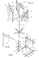
- FIG. 4a to 4c finally, an embodiment of the clothes display frame is shown, which starts from a single-column support device 16, where three symmetrically distributed horizontal arms 18 extend from the upper end of a standpipe 17.
- Each of these brackets 18 has at its radially outer end a tensioning device 19, in which, in a known manner, rotationally indexable extension tubes 20 are held vertically displaceably (and lockable).
- Each extension tube 20, shown individually in Fig. 5b, carries at its upper end a cantilever arm 3 'which is fixed to the extension tube 20.
- the angle of inclination ⁇ of the cantilever arm 3 ' is approximately 15 °.
- FIG. 4c From the plan view (FIG. 4c) it can be seen how the extension tubes 20 can be aligned to defined angular positions relative to the horizontal arms 18 by the rotationally indexed clamping devices 19. By preferably uniformly swiveling the extension tubes 20 vertically in the tensioning devices 19 in the direction of arrow A, the clothes display stands according to FIGS.
Landscapes
- Holders For Apparel And Elements Relating To Apparel (AREA)
Abstract
Die am Kleiderpräsentiergestell höhenverstellbar angebrachten Auslegearme (3) sind gegenüber ihrer Tragan- . ordnung (1, 2) unter einem Winkel α von etwa 105° schräg abwärts geneigt. Sie sind auf ihrer Oberseite mit V-förmigen Nuten (6) versehen, in welchen Kleiderbügel in horizontal und vertikal gestaffelter Anordnung einhängbar sind.
Description
Für die Präsentierung von Kleidungsstücken in Ausstellungs- und Verkaufsräumen ist es von wesentlicher Bedeutung, dass auf einem vorgegebenen Raumabschnitt eine maximale Anzahl Kleidungsstücke optimal vorgezeigt werden kann. Eine Möglichkeit hiezu besteht darin, dass die einzelnen Kleidungsstücke so gegeneinander versetzt aufgehängt werden, dass nicht nur vom jeweils vordersten Kleidungsstück ein grösserer Flächenbereich, sondern auch von den dahinterliegenden wenigstens ein schmaler vertikaler Ausschnitt sichtbar ist. Solche Gestelle sind in einer ersten Ausführungsform beispielsweise durch die DE-PS 2 941 648 und die DE-OS 2 916 226 bekannt geworden, wobei durch auf schrägen gegenseitig versetzten Tragstangen exzentrisch angebrachte Anschlagbolzen als Rückhaltemittel für übliche Kleiderbügel verwendet werden. Diese Rückhaltemittel bewirken, dass den Aufhängehaken von frei auf den Tragstangen aufliegenden Kleiderbügeln eine natürliche Ausschwenktendenz erteilt wird, durch die sich in der Horizontalprojektion eine Schrägstellung der Kleiderbügel von etwa 60° zur Tragstangen-Längsachse, und aus der Anordnung der Tragstangen selbst eine gute Raumausnützung ergibt.For the presentation of items of clothing in exhibition and sales rooms, it is essential that a maximum number of items of clothing can be optimally presented in a given section of the room. One possibility for this is that the individual items of clothing are hung offset from one another in such a way that not only a larger area is visible from the foremost item of clothing in each case, but also at least a narrow vertical cutout from the items behind it. Such racks are known in a first embodiment, for example, from DE-PS 2 941 648 and DE-OS 2 916 226, eccentrically attached stop bolts being used as retaining means for conventional hangers by means of support bolts which are offset from one another at an angle to one another. This restraint means that the hanging hooks of clothes hangers freely lying on the support rods are given a natural tendency to swing out, which results in a horizontal projection of the clothes hangers at an angle of approximately 60 ° to the longitudinal axis of the support rods and from the arrangement of the support rods themselves a good use of space .
Die Schrägstellung der Kleiderbügel erbringt zwar bei ausreichender Beweglichkeit zweier benachbarter Kleidungsstücke automatisch die erwünschte Exposition des Ausstellungsgutes. Wenn jedoch die Kleidungsstücke satt aneinanderliegen, reicht die dabei auftretende Haftung aus, um eine frei ablaufende Bewegung zu blockieren. Die Kleidungsstücke müssen dann von Hand bewegt werden, um den gewünschten Expositionseffekt erzielen zu können.The inclination of the hangers automatically results in the desired exposure of the exhibits if there is sufficient mobility of two adjacent items of clothing. However, if the garments fit snugly against one another, the resulting liability is sufficient to block a free-running movement. The bran Pieces of the piece must then be moved by hand in order to achieve the desired exposure effect.
In der europäischen Patentanmeldung 0 069 876 ist ein Kleiderständer gezeigt, bei dem die vorzugsweise radial von einer zentralen Säule abstehenden Tragarme mit einem Kunststoffüberzug versehen sind, der einen kammartig gestalteten Auflageabschnitt für die Aufnahme der Aufhängehaken von Kleiderbügeln aufweist. Die Kammzähne stehen unter einem Winkel von etwa 60° zur Tragarmlängsachse und erteilen den Aufhängehaken der Kleiderbügel eine entsprechend erzwungene Schrägstellung, so dass ein Ausrichten der Kleiderbügel entfallen kann. Der kammartig gestaltete Auflageabschnitt vermag zwar den gewünschten Ausrichteeffekt auf die Kleiderbügel zu erzeugen, doch bedingt die Erstellung des Kunststoffüberzuges eine Beschränkung auf Standardlängen, und die Ausformung der Zähne auf dem Kunststoffüberzug ist nicht problemlos.In European patent application 0 069 876 a clothes rack is shown, in which the support arms, which preferably protrude radially from a central column, are provided with a plastic covering, which has a comb-shaped support section for receiving the hanging hooks of clothes hangers. The comb teeth are at an angle of about 60 ° to the longitudinal axis of the support arm and give the hanging hooks of the hangers a correspondingly forced inclination, so that there is no need to align the hangers. The comb-like support section can produce the desired alignment effect on the clothes hangers, but the creation of the plastic cover places a restriction on standard lengths, and the shape of the teeth on the plastic cover is not easy.
Die Erfindung bezweckt die Schaffung eines Kleiderpräsentiergestells gemäss dem Oberbegriff des Patentanspruchs 1, bei dem insbesondere die Vorzüge einer fest indexierenden Rückhalte-Verzahnung auf den Auslegerarmen mitbenützt werden, aber darüberhinaus mit einer einfach anbringbaren spezifischen Verzahnung versehen ist. Ausserdem sollen die Auslegerarme an der Gestellkonstruktion wegnehmbar gestaltet sein, um eine optimale Ausnützung eines gegebenen Ausstellungsbereiches zu ermöglichen.The invention aims to create a clothes display frame according to the preamble of
Die Lösung der sich daraus ergebenden Aufgabe geht aus den kennzeichnenden Merkmalen des Patentanspruchs 1 hervor. Ausführungsformen davon sind durch die abhängigen Ansprüche definiert.The solution to the resulting task is evident from the characterizing features of
Die Erfindung ist nachstehend anhand der Zeichnung beispielsweise erläutert. Es zeigen:
- Fig. la bis c, und 2a bis c das erfindungsgemässe Kleiderpräsentiergestell in zwei typischen Wand-Ausführungsformen mit je einem perspektivischen, einer Grundrissdarstellung und einer Seitenrissdarstellung (Fig. lc, 2c) der Kleidertraganordnung;
- Fig. 3a, 3b eine Einsäulenausführungsform mit einem Standrohr und fester oder fahrbarer Fussanordnung und Auslegerarmen, die fest an einem im Standrohr teleskopisch höhenverstellbaren Auszugsrohr angeordnet sind; und
- Fig. 4a bis c eine weitere Einsäulenausführungsform mit horizontal-radialen Auslegern, an deren Enden je ein höhenverstellbares Auszugsrohr mit einem Kleiderbügelausleger festgehalten ist.
- Fig. La to c, and 2a to c, the clothing display frame according to the invention in two typical wall embodiments, each with a perspective, a plan view and a side view (Fig. Lc, 2c) of the clothes support arrangement;
- 3a, 3b a single-column embodiment with a standpipe and a fixed or movable foot arrangement and extension arms, which are fixedly arranged on a telescopic height-adjustable extension pipe in the standpipe; and
- 4a to c a further single-column embodiment with horizontal-radial arms, at the ends of which a height-adjustable extension tube is held with a clothes hanger arm.
In Fig. la ist eine erste Ausführungsform des erfindungsgemässen Kleiderpräsentiergestells gezeigt, wo an Säulengliedern 1 oder anderen Trag- oder Befstigungsmitteln einer aus Wandelementen 2 aufgebauten Raumunterteilungs-oder Rückwandanordnung Auslegerarme 3 mit einer Rastenanordnung 4 gemäss Fig. lc auf bekannte Weise auf wählbaren Höhenlagen einhängbar sind. Die Auslegerarme sind etwa um den Winkel α = 90+150 = 105° abwärts geneigt.1 a shows a first embodiment of the clothing presentation frame according to the invention, where
Aus der Grundrissdarstellung von Fig. lb sind die beiden in der Perspektivzeichnung gezeigten Auslegerarme 3 in ihrer winkelmässigen Beziehung bezüglich der Wandelemente 2 ersichtlich. Der Auslegerarm links steht linksdrehend unter einem spitzen Winkel ß1, der Ausleger rechts rechtsdrehend unter einem etwa gleich grossen Winkel ß2 zu den Wandelementen 2. Die Winkel ß1, ß2 betragen je ca. 90 -30°=60°, so dass die Kleidungsstücke etwa parallel zur Wand hängen. Die Schiefstellung benachbarter Ausleger kann selbstverständlich an der gleichen Wandanordnung einheitlich nach links oder nach rechts drehend gewählt werden. Massgebend hiefür ist die Relativstellung eines Anklemmgliedes 5 am Auslegerarm 3, wie aus Fig. lc ersichtlich ist. An diesem Anklemmglied 5, bestehend aus einer aus einem flachen Bandmaterial gestanzten Hakenlasche 5.1 und einer der Oberfläche des Säulengliedes 1 angepassten Schildplatte 5.2, ist unter einem Winkel γ von etwa 15° der die Rasteranordnung 4 aufweisende Auslegerarm 3 angebracht. Der Auslegerarm 3 steht unter einem Winkel ω von etwa 30° zur Hakenlasche und enthält V-förmige Nuten 6, deren untere Flanke 6.1 etwa rechtwinklig zur Auslegerarm-Erstrekkung steht, während die obere Flanke 6.2 unter einem Winkel von 35-38° nach oben geneigt ist. Ausserdem stehen die Nuten 6, von oben gesehen, unter einem Winkel τ von etwa 60° schräg zum Auslegerarm 3. Diese Schrägstellung der etwa 10 mm tiefen und unter einer Teilung T von etwa 20-25 mm stehenden Nuten 6 bewirkt, dass die (in Fig. lb) schematisch gezeigten Haken 7 der Kleiderbügel 8 diesen in eine entsprechende Schrägstellung zum Auslegerarm 3 drängen. Damit ist die erwünschte gestaffelte Präsentation des auf derbügel 8 aufgelegten Kleidungsstückes zwangsweise herbeigeführt.From the plan view of Fig. Lb are the the two
Es versteht sich, dass die T-Schrägstellung der Nuten 6 auch spiegelsymmetrisch gewählt werden kann, um eine entgegengesetzte Schrägstellung der Kleiderbügel erzielen zu können. Siehe hiezu auch Fig. 3b.It goes without saying that the T-inclination of the
Fig. 2a zeigt eine zweite Ausführungsform des Kleiderpräsentiergestells, bei dem als Trageinrichtung wiederum eine Raumunterteilungs- oder Rückwandanordnung nach Fig. la verwendbar ist. An den Säulengliedern 1 sind horizontale Ausleger 9 eingehängt, an deren vorderem Ende jeweils das eine Ende einer die Aufgabe eines Auslegerarms 3 übernehmenden Tragstange 10 mit einer schematisch gezeigten Rasteranordnung 4 nach Fig. lc befestigt ist. Die Tragstange 10 verläuft gemäss Fig. 2c und analog Fig. lc zwischen den Säulengliedern 1 unter dem Winkel γ von etwa 150 geneigt, wobei die Neigung im Uhrzeigersinn oder im Gegenzeigersinn laufen kann. Der sich dabei ergebende Höhenunterschied H bei den Auslegern 9 entspricht einem ganzzahligen Vielfachen des Abstandes benachbarter indexierter Einhängestellen an den Säulengliedern 1. Wie die Grundrissdarstellung Fig. 2b zeigt, stehen die Kleiderbügel 8 unter dem Winkel τ schräg zur Tragstange. Diese Schrägstellung kann bedarfsweise links- oder rechtsdrehend verlaufen.FIG. 2a shows a second embodiment of the clothes display frame, in which a space partitioning or rear wall arrangement according to FIG.
Eine Einsäulen-Ausführungsform des Kleiderpräsentiergestells geht aus den Fig. 3a, 3b hervor. Ein Standrohr 13, das auf einer ortsfesten oder fahrbaren Fussanordnung 14 angeordnet ist, führt ein in seinem Inneren teleskopierendes und fixierbares Auszugsrohr 15. An dessen oberem Ende ist eine Anzahl (im Beispiel zwei) mit je einer Rastenanordnung 4 (Fig. lc) versehene Auslegerarme 3 angebracht, die analog der früher beschriebenen Darstellungen unter einem Winkel r von ca. 15° nach aussen-abwärts geneigt sind. Die Anzahl der Auslegerarme 3' kann an sich beliebig gewählt werden. Bei der in Fig. 3b gezeigten zweiarmigen Ausführungsform stehen die Arme 3' unter einem Winkel von etwa 120° V-förmig zueinander, wobei sie symmetrisch zur Auszugrohrebene X-X angeordnet sind. Zusammen mit den Anwinklungen 1 der Nuten 6 (Fig. lc), die-wie erwähnt, an den Armen 3' nach links oder nach rechts orientiert sein können. ergibt sich für die Kleiderbügel 8 auf den beiden Armen 3' eine Parallelstellung.A one-column embodiment of the clothes display frame can be seen in FIGS. 3a, 3b. A
In den Fig. 4a bis 4c ist schliesslich eine Ausführungsform des Kleiderpräsentiergestells gezeigt, die von einer Einsäulen-Trageinrichtung 16 ausgeht, wo vom oberen Ende eines Standrohres 17 drei symmetrisch verteilte horizontale Ausleger 18 ausgehen. Jeder dieser Ausleger 18 weist an seinem radial äusseren Ende eine Spanneinrichtung 19 auf, in welcher auf bekannte Weise dreh-indexierbare Auszugrohre 20 vertikal verschiebbar (und arretierbar) gehalten sind. Jedes Auszugrohr 20, in Fig. 5b einzeln dargestellt, trägt an seinem oberen Ende einen Auslegerarm 3', der mit dem Auszugrohr 20 fest verbunden ist. Der Neigungswinkel γ des Auslegerarms 3' beträgt wie früher erwähnt, ca. 15°.4a to 4c, finally, an embodiment of the clothes display frame is shown, which starts from a single-
Aus der Grundrissdarstellung (Fig. 4c) ist ersichtlich, wie die Auszugrohre 20 durch die dreh-indexierten Spanneinrichtungen 19 auf definierte Winkelstellungen relativ zu den horizontalen Auslegern 18 ausrichtbar sind. Durch vorzugsweise gleichmässiges vertikalen Verschwenken der Auszugrohre 20 in den Spanneinrichtungen 19 in Pfeilrichtung A lassen sich Kleiderpräsentierständer nach Fig. 4a-c leicht an unterschiedlich grosse Kleidungsstücke anpassen.From the plan view (FIG. 4c) it can be seen how the
Claims (9)
Applications Claiming Priority (2)
| Application Number | Priority Date | Filing Date | Title |
|---|---|---|---|
| CH3200/86 | 1986-08-08 | ||
| CH3200/86A CH672980A5 (en) | 1986-08-08 | 1986-08-08 |
Publications (2)
| Publication Number | Publication Date |
|---|---|
| EP0255884A2 true EP0255884A2 (en) | 1988-02-17 |
| EP0255884A3 EP0255884A3 (en) | 1989-12-20 |
Family
ID=4250818
Family Applications (1)
| Application Number | Title | Priority Date | Filing Date |
|---|---|---|---|
| EP87110271A Withdrawn EP0255884A3 (en) | 1986-08-08 | 1987-07-16 | Clothes display support |
Country Status (4)
| Country | Link |
|---|---|
| US (1) | US4813552A (en) |
| EP (1) | EP0255884A3 (en) |
| AU (1) | AU594273B2 (en) |
| CH (1) | CH672980A5 (en) |
Cited By (3)
| Publication number | Priority date | Publication date | Assignee | Title |
|---|---|---|---|---|
| EP0389764A1 (en) * | 1989-03-25 | 1990-10-03 | Connec AG Systembau-Technik | Support element especially for display, fair stands and the like |
| DE10205999A1 (en) * | 2002-02-14 | 2003-09-04 | Kurt Faehnrich | Holder for clothes hangers on clothes rail, e.g. in street market, has central bar with groove which fits over rail and serrated end bars which project forwards with respect to central section |
| DE102008010405A1 (en) | 2008-02-21 | 2009-08-27 | Hans-Georg Kraiss | Presentation element, particularly for sheathing, has rear wall and multiple receiving slots that are arranged in rear wall for fixing hanging element in detachable manner, where hanging element has foot area with detent element |
Families Citing this family (20)
| Publication number | Priority date | Publication date | Assignee | Title |
|---|---|---|---|---|
| US4946049A (en) * | 1989-09-08 | 1990-08-07 | Bigsby & Kruthers, Inc. | Tie display assembly |
| AU631455B2 (en) * | 1989-09-15 | 1992-11-26 | Rainsfords Pty Limited | Improvements in support brackets |
| USD335623S (en) | 1991-04-08 | 1993-05-18 | Lancaster Colony Corporation | Angled display fixture |
| US5152404A (en) * | 1991-04-08 | 1992-10-06 | Lancaster Colony Corporation | Angled fixture and display assembly |
| USD358506S (en) | 1994-03-09 | 1995-05-23 | Joe Lara | Pull apart clothes rack for a pickup truck |
| DE4422433A1 (en) * | 1994-06-28 | 1996-01-04 | Cognis Bio Umwelt | Multi-enzyme granules |
| USD369035S (en) | 1995-04-03 | 1996-04-23 | Tie Rack Trading Limited | Display unit for ties |
| US5819961A (en) * | 1996-01-22 | 1998-10-13 | Hidea Innovative Products, L.C. | Portable valet |
| CA2215823A1 (en) | 1997-09-19 | 1999-03-19 | Robert Winikoff | Display unit |
| US20040188370A1 (en) * | 2003-03-26 | 2004-09-30 | Nawrocki John Richard | Organizing device |
| US20100127136A1 (en) * | 2008-01-21 | 2010-05-27 | Brad Markoff | Lug-mount system for free standing display stand arm |
| US20090184215A1 (en) * | 2008-01-21 | 2009-07-23 | Brad Markoff | Lug-mount system for free standing display stand arm |
| US20090283485A1 (en) * | 2008-05-16 | 2009-11-19 | Eric Anderson | Combination headwear / apparel display |
| CA2761451A1 (en) * | 2010-12-09 | 2012-06-09 | Ntd Apparel Inc. | Multi-direction garment display module |
| USD756154S1 (en) * | 2013-07-24 | 2016-05-17 | Visplay International Ag | Display equipment |
| CN104433535B (en) * | 2014-12-01 | 2017-07-25 | 嘉兴职业技术学院 | A kind of clothes display cabinet |
| CA2943123A1 (en) * | 2016-09-27 | 2018-03-27 | Robert Winikoff | A display rack |
| CN107898237B (en) * | 2017-12-15 | 2020-02-11 | 佛山市富矿智能家居有限公司 | a clothes rack |
| CN108793021B (en) * | 2018-06-26 | 2019-12-03 | 宿州学院 | A kind of garment production material lifting device |
| US11937552B2 (en) * | 2019-10-09 | 2024-03-26 | DriFlower, LLC | Vegetation hanger |
Family Cites Families (15)
| Publication number | Priority date | Publication date | Assignee | Title |
|---|---|---|---|---|
| GB778628A (en) * | 1954-05-31 | 1957-07-10 | Leon Weinstein | Improvements in or relating to display stands for garments or the like |
| US3071253A (en) * | 1957-07-02 | 1963-01-01 | Cal Dak Company | Clothes support |
| US3202297A (en) * | 1964-04-03 | 1965-08-24 | Peerless Aluminum Foundry Co I | Clothes display stand |
| US3286850A (en) * | 1964-11-16 | 1966-11-22 | Garcy Corp | Hang rod assembly |
| US3739920A (en) * | 1971-03-15 | 1973-06-19 | Foster Grant Co Inc | Fixture for supporting rotary display racks |
| US4181230A (en) * | 1977-12-16 | 1980-01-01 | Darling Store Fixtures, a division of the Marmon Group, Inc. | Store display fixture |
| US4253578A (en) * | 1979-04-16 | 1981-03-03 | Rekow John A | Merchandise display rack |
| DE2941468C3 (en) * | 1979-10-12 | 1982-03-11 | PFP-Anstalt für Produktentwicklung und Verwertung, Schaan | Support bar for hanging goods on hooks |
| US4316547A (en) * | 1980-03-14 | 1982-02-23 | Crown Metal Manufacturing Co. | Hang rail support and hang rail |
| US4548328A (en) * | 1981-07-10 | 1985-10-22 | Protoned B.V. | Clothes stand |
| FR2534794A1 (en) * | 1982-10-22 | 1984-04-27 | Enfi Design | Support/display unit for articles in shops. |
| CH658982A5 (en) * | 1983-01-28 | 1986-12-31 | Fehlbaum & Co | CONFECTION HOLDER. |
| US4585131A (en) * | 1983-12-19 | 1986-04-29 | Amstore Corporation | Variable decor merchandising system |
| GB2189138B (en) * | 1986-04-17 | 1989-12-28 | Jr Comm Enterprises Ltd | Display post |
| DE8612892U1 (en) * | 1986-05-12 | 1986-06-26 | Brüder Assmann, Leibnitz, Steiermark | Goods racks |
-
1986
- 1986-08-08 CH CH3200/86A patent/CH672980A5/de not_active IP Right Cessation
-
1987
- 1987-07-15 US US07/073,453 patent/US4813552A/en not_active Expired - Fee Related
- 1987-07-16 EP EP87110271A patent/EP0255884A3/en not_active Withdrawn
- 1987-07-23 AU AU76119/87A patent/AU594273B2/en not_active Ceased
Cited By (3)
| Publication number | Priority date | Publication date | Assignee | Title |
|---|---|---|---|---|
| EP0389764A1 (en) * | 1989-03-25 | 1990-10-03 | Connec AG Systembau-Technik | Support element especially for display, fair stands and the like |
| DE10205999A1 (en) * | 2002-02-14 | 2003-09-04 | Kurt Faehnrich | Holder for clothes hangers on clothes rail, e.g. in street market, has central bar with groove which fits over rail and serrated end bars which project forwards with respect to central section |
| DE102008010405A1 (en) | 2008-02-21 | 2009-08-27 | Hans-Georg Kraiss | Presentation element, particularly for sheathing, has rear wall and multiple receiving slots that are arranged in rear wall for fixing hanging element in detachable manner, where hanging element has foot area with detent element |
Also Published As
| Publication number | Publication date |
|---|---|
| AU7611987A (en) | 1988-02-11 |
| US4813552A (en) | 1989-03-21 |
| AU594273B2 (en) | 1990-03-01 |
| EP0255884A3 (en) | 1989-12-20 |
| CH672980A5 (en) | 1990-01-31 |
Similar Documents
| Publication | Publication Date | Title |
|---|---|---|
| EP0255884A2 (en) | Clothes display support | |
| DE2232398C3 (en) | Goods sales device for small parcels | |
| EP0069876A2 (en) | Clothes rack | |
| DE69210300T2 (en) | Angled bracket and display assembly | |
| CH675196A5 (en) | ||
| AT391992B (en) | GOODS PRESENTATION RACK | |
| DE2936767C2 (en) | Dismountable open-plan shelving | |
| DE3040276C2 (en) | Sales stand for the presentation of shoe items in profile | |
| DE3530714C2 (en) | ||
| DE102012017852B3 (en) | Device for displaying product e.g. packaged good, has adjustable telescopic plates that are mounted in variable mounting positions on vertical base column at preset mounting distance, to form multi-link function unit | |
| DE10306537B4 (en) | System for presenting objects | |
| EP0558446B1 (en) | Side frame members for article display racks | |
| EP0611534A1 (en) | Rack for book shelf | |
| DE8421274U1 (en) | LAUNDRY HOLDER OD. DGL. | |
| DE2451246C3 (en) | Frame for the display of flat patterns, in particular carpet patterns | |
| DE2407547C3 (en) | Cloakroom rack | |
| CH682622A5 (en) | Frame for height-adjustable shelves - comprises profiled bars with base plates parallel to wall with pairs of mirror-image ribs at front and rear | |
| DE8220319U1 (en) | DEVICE FOR SUPPORTING AND HOLDING TIRES | |
| DE8790001U1 (en) | Multiple coat hanger rack | |
| DE4124349A1 (en) | Modular goods display system with wooden column - has a ridged parts alternating the smooth parts on its periphery, and U=shaped rods fitting round for holding goods holders | |
| DE7504713U (en) | shelf | |
| DE8104414U1 (en) | Ski pole holder | |
| DE2916226A1 (en) | Sales display stand for clothing on hangers - has hangers running parallel to support arms via angled rods for better use of space | |
| DE1271336B (en) | Steel tube feet to support a free-standing shelf | |
| DE7820753U1 (en) | DEVICE FOR HOLDING BOOTS, SUCH AS RUBBER BOOTS OR WADDING BOOTS, AND PANTS, SUCH AS WADDING PANTS AND WEATHER PANTS |
Legal Events
| Date | Code | Title | Description |
|---|---|---|---|
| PUAI | Public reference made under article 153(3) epc to a published international application that has entered the european phase |
Free format text: ORIGINAL CODE: 0009012 |
|
| AK | Designated contracting states |
Kind code of ref document: A2 Designated state(s): AT BE DE FR GB NL |
|
| PUAL | Search report despatched |
Free format text: ORIGINAL CODE: 0009013 |
|
| AK | Designated contracting states |
Kind code of ref document: A3 Designated state(s): AT BE DE FR GB NL |
|
| 17P | Request for examination filed |
Effective date: 19900209 |
|
| 17Q | First examination report despatched |
Effective date: 19910227 |
|
| STAA | Information on the status of an ep patent application or granted ep patent |
Free format text: STATUS: THE APPLICATION IS DEEMED TO BE WITHDRAWN |
|
| 18D | Application deemed to be withdrawn |
Effective date: 19920623 |
|
| RIN1 | Information on inventor provided before grant (corrected) |
Inventor name: WALTER, HERBERT |