EP0255620B2 - Rollerway for conveyor dollies for motor vehicle bodies - Google Patents
Rollerway for conveyor dollies for motor vehicle bodies Download PDFInfo
- Publication number
- EP0255620B2 EP0255620B2 EP87109910A EP87109910A EP0255620B2 EP 0255620 B2 EP0255620 B2 EP 0255620B2 EP 87109910 A EP87109910 A EP 87109910A EP 87109910 A EP87109910 A EP 87109910A EP 0255620 B2 EP0255620 B2 EP 0255620B2
- Authority
- EP
- European Patent Office
- Prior art keywords
- drive
- bearing rollers
- drive shafts
- frame
- pinions
- Prior art date
- Legal status (The legal status is an assumption and is not a legal conclusion. Google has not performed a legal analysis and makes no representation as to the accuracy of the status listed.)
- Expired - Lifetime
Links
Images


Classifications
-
- B—PERFORMING OPERATIONS; TRANSPORTING
- B62—LAND VEHICLES FOR TRAVELLING OTHERWISE THAN ON RAILS
- B62D—MOTOR VEHICLES; TRAILERS
- B62D65/00—Designing, manufacturing, e.g. assembling, facilitating disassembly, or structurally modifying motor vehicles or trailers, not otherwise provided for
- B62D65/02—Joining sub-units or components to, or positioning sub-units or components with respect to, body shell or other sub-units or components
- B62D65/18—Transportation, conveyor or haulage systems specially adapted for motor vehicle or trailer assembly lines
-
- B—PERFORMING OPERATIONS; TRANSPORTING
- B65—CONVEYING; PACKING; STORING; HANDLING THIN OR FILAMENTARY MATERIAL
- B65G—TRANSPORT OR STORAGE DEVICES, e.g. CONVEYORS FOR LOADING OR TIPPING, SHOP CONVEYOR SYSTEMS OR PNEUMATIC TUBE CONVEYORS
- B65G13/00—Roller-ways
- B65G13/02—Roller-ways having driven rollers
- B65G13/06—Roller driving means
- B65G13/07—Roller driving means having endless driving elements
-
- B—PERFORMING OPERATIONS; TRANSPORTING
- B65—CONVEYING; PACKING; STORING; HANDLING THIN OR FILAMENTARY MATERIAL
- B65G—TRANSPORT OR STORAGE DEVICES, e.g. CONVEYORS FOR LOADING OR TIPPING, SHOP CONVEYOR SYSTEMS OR PNEUMATIC TUBE CONVEYORS
- B65G13/00—Roller-ways
- B65G13/11—Roller frames
Definitions
- the invention relates to a roller conveyor for vehicle body transport sledges, with a frame extending in the transport direction with lateral frame legs, between which a plurality of drive shafts are rotatably mounted one behind the other, each having two support rollers for resting and two wheel flanges for guiding transport sled runners and in pairs via a drive connection in each case , which on the drive shafts, adjacent to one of the support rollers, comprise fixed pinions, coupled to one another and thus drivable as a whole, the pinions and the drive shafts having a smaller diameter than the support rollers, and with one of at least one cover plate and extending over the pinions as well as the cover of the drive shaft areas of smaller diameter for covering frame fields located between the drive shafts, which window-like openings for the passage of the idlers and also next to these on the A has drive flanges attached to the flanges.
- each of the undivided drive shafts carries a sprocket wheel adjacent to one of the side longitudinal frame legs of the frame, over which a transport chain driven by a gear motor runs.
- Each of the drive shafts has essentially the same diameter everywhere between the two lateral longitudinal frame legs of the frame and thus forms a single support roller on which the two runners of the transport slides rest, the one sled runner being guided between two wheel flanges attached to the support roller.
- the idlers protrude approximately one tenth of their diameter beyond the level formed by several cover plates arranged one behind the other in the direction of transport, so that there is a transverse slot in the cover between each two cover plates, which releases the idlers and the wheel flanges.
- the lateral longitudinal legs of the frame frame have a roughly C-shaped profile in vertical section perpendicular to the transport direction, which is open towards the center of the roller conveyor, so that one Longitudinal leg of the frame frame overlaps and covers the sprockets and the drive chain.
- L-shaped support brackets are attached to the lateral longitudinal edges of the cover plates, which rest on the longitudinal legs of the frame and thus form a trough extending in the transport direction, the bottom of which is interrupted by the support rollers, together with the cover plates.
- each drive shaft has two pinions, which are arranged between one supporting roller and one side frame leg and at which are sprockets, d. H. the drive connections for coupling successive drive shafts in pairs consist of gearwheel-like sprockets and link chains running over these. Furthermore, each drive shaft of this roller conveyor has two wheel flanges which are arranged on either side of one of the two support rollers. The cover is folded down at its two longitudinal edges, lies on the side frame legs and is attached to them.
- the invention was based on the object of designing this roller conveyor of the type mentioned at the outset in such a way that, despite a cover which forms a top of the roller conveyor and minimizes the risk of contamination of all parts of the roller conveyor, the overall height and width are as small as possible, which is achieved according to the invention lets the sprockets be arranged between the support rollers of the drive shaft in question corresponding in width to those of a transport sled runner and designed as toothed pulleys over which toothed belts the drive connections run, and that the wheel flanges are arranged adjacent to the outer sides of the support rollers of the drive shaft in question.
- toothed belts and toothed pulleys By using toothed belts and toothed pulleys, the advantage is achieved that a toothed pulley with a smaller diameter can be formed than a sprocket, so that the height of the roller conveyor and in particular the height of the cover plate can be reduced compared to a roller conveyor driven by chains and sprockets , although the drive connections are located under the cover plate.
- roller conveyor according to the invention which can be manufactured particularly cheaply and is particularly low, is obtained when the two lateral frame legs are of identical design and have an approximately Z-shaped cross section, the support rollers protrude beyond the lateral frame legs and the cover plate on the frame legs rests with lateral edge areas and the latter form a plane together with the cover plate areas covering the drive shafts.
- the lateral frame frame legs can be produced from a single profile in such a way that they run and are mirror images of the longitudinal center plane of the frame.
- a frame of the roller conveyor designated as a whole by 10, essentially consists of lateral longitudinal beams 14 and cross beams 16 standing on individually height-adjustable feet 12, which are arranged one behind the other at uniform distances from one another in the transport direction F and are attached to the longitudinal beams 14 with their ends.
- Bearing devices 18 are attached to the longitudinal beams 14 at equal distances from one another, which serve for the rotatable mounting of drive shafts designated as a whole by 20.
- drive shafts will be explained in more detail with reference to FIG. 3.
- the drive shaft has a shaft 22 on which two support rollers 24 and 26 are fastened at a distance from one another.
- the width of each support roller 24, 26 corresponds to the width of one of the runners 28 indicated by dashed lines of the transport slides, not shown in the rest
- the center distance A of the two support rollers 24 and 26 from one another is equal to the center distance of the runners 28 or those areas of the transport slides which they rest on the idlers, and apart from parts of the drive shafts 20 to be discussed below
- the shaft shaft 22 has a much smaller diameter than the idlers 24 and 26 everywhere.
- FIG. 2 shows an electric geared motor 40, on the output shaft of which two toothed disks 42 and 44 are fastened.
- a toothed belt 46 or 48 runs over each of these, which also runs over one of the toothed pulleys 30 and 32 of the adjacent drive shafts 20.
- the longitudinal beams 14 have an approximately Z-shaped profile (see FIG. 3), the upper leg of which is at a level slightly below the tips of the support rollers 24 and 26.
- Tabular cover plates 70 which are bent downwards at their lateral longitudinal edges at 50 and at their front and rear edges (seen in the direction of transport) at 52, are now placed on this longitudinal member and on the upper ones Legs 14a of the side members 14 are fastened, for example by means of screws.
- These cover plates abut against each other in the longitudinal direction of the roller conveyor and thus result in an essentially complete cover. They have only relatively small, window-shaped openings 72 for the passage of one of the support rollers 24, 26 and a flange 34.
- the toothed disks 30 and 32 used according to the invention can be produced with a significantly smaller outside diameter than sprockets, so that the diameter of a toothed disk with over it running toothed belt is significantly less than that of the idlers, which has an advantageous effect on the use of a continuous cover.
- the small diameter of the toothed pulleys 30, 32 compared to sprockets there is still space for the toothed belts 46 under the folds 52, despite the low overall height of the roller conveyor according to the invention.
- the cover plates according to the invention extend over all areas of the drive shafts that lie between the lateral frame frame legs.
Description
Die Erfindung betrifft eine Rollenbahn für Fahrzeugkarosserie-Transportschlitten, mit einem sich in Transportrichtung erstreckenden Gestell mit seitlichen Rahmenschenkeln, zwischen denen hintereinander mehrere Antriebswellen drehbar gelagert sind, welche jeweils zwei Tragrollen zum Aufliegen und zwei Spurkränze zum Führen von Transportschlittenkufen aufweisen und paarweise über jeweils eine Triebverbindung, die an den Antriebswellen, einer der Tragrollen benachbart, befestigte Ritzel umfaßt, miteinander gekoppelt und so insgesamt antreibbar sind, wobei die Ritzel und die Antriebswellen einen kleineren Durchmesser als die Tragrollen aufweisen, sowie mit einer von mindestens einer Abdeckplatte gebildeten und sich über die Ritzel sowie die Antriebswellenbereiche kleineren Durchmessers erstreckenden Abdeckung zum Abdecken von sich zwischen den Antriebswellen befindenden Gestellfeldern, welche fensterartige Öffnungen für den Durchtritt der Tragrollen sowie der neben diesen auf den Antriebswellen angebrachten Spurkränze aufweist.The invention relates to a roller conveyor for vehicle body transport sledges, with a frame extending in the transport direction with lateral frame legs, between which a plurality of drive shafts are rotatably mounted one behind the other, each having two support rollers for resting and two wheel flanges for guiding transport sled runners and in pairs via a drive connection in each case , which on the drive shafts, adjacent to one of the support rollers, comprise fixed pinions, coupled to one another and thus drivable as a whole, the pinions and the drive shafts having a smaller diameter than the support rollers, and with one of at least one cover plate and extending over the pinions as well as the cover of the drive shaft areas of smaller diameter for covering frame fields located between the drive shafts, which window-like openings for the passage of the idlers and also next to these on the A has drive flanges attached to the flanges.
Durch die Firma Dürr GmbH ist bereits eine Rollenbahn für Fahrzeugkarosserie-Transportschlitten bekanntgeworden, bei der jede der ungeteilten Antriebswellen dem einen der seitlichen Längsrahmenschenkel des Gestells benachbart ein Kettenzahnrad trägt, über das eine durch einen Getriebemotor angetriebene Transportkette verläuft. Jede der Antriebswellen hat zwischen den beiden seitlichen Längsrahmenschenkeln des Gestells im wesentlichen überall denselben Durchmesser und bildet so eine einzige Tragrolle, auf der die beiden Kufen der Transportschlitten aufliegen, wobei die eine Schlittenkufe zwischen zwei auf der Tragrolle befestigten Spurkränzen geführt wird.Dürr GmbH has already made known a roller conveyor for vehicle body transport sledges, in which each of the undivided drive shafts carries a sprocket wheel adjacent to one of the side longitudinal frame legs of the frame, over which a transport chain driven by a gear motor runs. Each of the drive shafts has essentially the same diameter everywhere between the two lateral longitudinal frame legs of the frame and thus forms a single support roller on which the two runners of the transport slides rest, the one sled runner being guided between two wheel flanges attached to the support roller.
Die Tragrollen ragen ungefähr mit einem Zehntel ihres Durchmessers über die von mehreren, in Transportrichtung hintereinander angeordneten Abdeckplatten gebildete Ebene hinaus, so dass sich in der Abdeckung zwischen jeweils zwei Abdeckplatten ein Querschlitz ergibt, der die Tragrollen und die Spurkränze freigibt. Damit die Triebverbindungen, über die die Antriebswellen miteinander verbunden sind und angetrieben werden, möglichst wenig verschmutzen, besitzen die seitlichen Längsschenkel des Gestellrahmens im Vertikalschnitt senkrecht zur Transportrichtung ein ungefähr C-förmiges Profil, welches zur Rollenbahn-Längsmitte hin offen ist, so dass der eine Längsschenkel des Gestellrahmens die Kettenzahnräder und die Antriebskette überfängt und abdeckt. An den seitlichen Längskanten der Abdeckplatten sind umgekehrt L-förmige Tragwinkel befestigt, die auf den Längsschenkeln des Gestellrahmens aufliegen und so zusammen mit den Abdeckplatten eine sich in Transportrichtung erstreckende Mulde bilden, deren Boden von den Tragrollen unterbrochen wird.The idlers protrude approximately one tenth of their diameter beyond the level formed by several cover plates arranged one behind the other in the direction of transport, so that there is a transverse slot in the cover between each two cover plates, which releases the idlers and the wheel flanges. So that the drive connections via which the drive shafts are connected and driven are soiled as little as possible, the lateral longitudinal legs of the frame frame have a roughly C-shaped profile in vertical section perpendicular to the transport direction, which is open towards the center of the roller conveyor, so that one Longitudinal leg of the frame frame overlaps and covers the sprockets and the drive chain. Conversely, L-shaped support brackets are attached to the lateral longitudinal edges of the cover plates, which rest on the longitudinal legs of the frame and thus form a trough extending in the transport direction, the bottom of which is interrupted by the support rollers, together with the cover plates.
Bei einer anderen bekannten Rollenbahn für Fahrzeugkarosserie-Transportschlitten sind an seitlichen Längsschenkeln eines Gestellrahmens Tragrollen gelagert, wobei einander gegenüberliegende Tragrollen nicht durch Antriebswellen miteinander verbunden sind. Deshalb benötigt diese bekannte Rollenbann an beiden Längsseiten Triebverbindungen in Form jeweils eines Kettenzahnrads pro Tragrolle und mehrerer Antriebsketten, wobei durch jeweils eine Antriebskette zwei einander in Transportrichtung benachbarte Tragrollen miteinander verbunden werden.In another known roller conveyor for vehicle body transport slides, support rollers are mounted on the longitudinal side legs of a frame, wherein opposite support rollers are not connected to one another by drive shafts. Therefore, this known roller ban requires drive connections in the form of a chain sprocket per idler roller and several drive chains on both longitudinal sides, two idler rollers adjacent to one another in the transport direction being connected to one another by means of one drive chain.
Bei einer älteren Rollenbahn der Firma DE-MAG für nicht näher spezifiziertes Transportgut handelt es sich im übrigen um eine Rollenbahn der eingangs erwähnten Art. Bei dieser Rollenbahn besitzt jede Antriebswelle zwei Ritzel, die zwischen der einen Tragrolle und dem einen seitlichen Rahmenschenkel angeordnet sind und bei denen es sich um Kettenräder handelt, d. h. die Triebverbindungen zum paarweisen Koppeln aufeinanderfolgender Antriebswellen bestehen aus zahnradartigen Kettenrädern und über diese verlaufenden Gliederketten. Des weiteren weist jede Antriebswelle dieser Rollenbahn zwei Spurkränze auf, die zu beiden Seiten einer der beiden Tragrollen angeordnet sind. Die Abdeckung ist an ihren beiden Längsrändern nach unten abgekantet, liegt auf den seitlichen Rahmenschenkeln auf und ist an diesen befestigt.An older roller conveyor from DE-MAG for unspecified transport goods is, moreover, a roller conveyor of the type mentioned at the outset. In this roller conveyor, each drive shaft has two pinions, which are arranged between one supporting roller and one side frame leg and at which are sprockets, d. H. the drive connections for coupling successive drive shafts in pairs consist of gearwheel-like sprockets and link chains running over these. Furthermore, each drive shaft of this roller conveyor has two wheel flanges which are arranged on either side of one of the two support rollers. The cover is folded down at its two longitudinal edges, lies on the side frame legs and is attached to them.
Der Erfindung lag die Aufgabe zugrunde, diese Rollenbahn der eingangs erwähnten Art so auszubilden, daß sie trotz einer eine Rollenbahn-Oberseite bildenden und die Verschmutzungsgefahr aller Teile der Rollenbahn minimierenden Abdeckung eine möglichst geringe Bauhöhe und eine möglichst kleine Breite aufweist, was sich erfindungsgemäß dadurch erreichen läßt, daß die Ritzel zwischen den in ihrer Breite derjenigen einer Transportschlittenkufe entsprechenden Tragrollen der betreffenden Antriebswelle angeordnet und als Zahnscheiben ausgebildet werden, über welche Zahnriemen der Triebverbindungen verlaufen, und daß die Spurkränze den Außenseiten der Tragrollen der betreffenden Antriebswelle benachbart angeordnet werden.The invention was based on the object of designing this roller conveyor of the type mentioned at the outset in such a way that, despite a cover which forms a top of the roller conveyor and minimizes the risk of contamination of all parts of the roller conveyor, the overall height and width are as small as possible, which is achieved according to the invention lets the sprockets be arranged between the support rollers of the drive shaft in question corresponding in width to those of a transport sled runner and designed as toothed pulleys over which toothed belts the drive connections run, and that the wheel flanges are arranged adjacent to the outer sides of the support rollers of the drive shaft in question.
Durch die erfindungsgemäße Lösung lassen sich folgende Vorteile erzielen:
- Da die Kufen der zu transportierenden Fahrzeugkarosserie-Transportschlitten einen vorgegebenen Querabstand voneinander haben, gilt dies auch für den Querabstand der beiden Tragrollen der erfindungsgemäßen Rollenbahn bzw. der durch die Erfindung verbesserten älteren Rollenbahn, wenn letztere mit Fahrzeugkarosserie-Transportschlitten zusammenwirken soll. Da bei der erfindungsgemäßen Rollenbahn die Ritzel zwischen den einen bestimmten Querabstand voneinander aufweisenden Tragrollen angeordnet sind, läßt sich die erfindungsgemäße Rollenbahn wenigstens um die Breite des Ritzelpaares schmäler gestalten als die durch die Erfindung verbesserte ältere Rollenbahn.
- Since the runners of the vehicle body transport sledge to be transported have a predetermined transverse distance from one another, this also applies to the transverse distance of the two support rollers of the roller conveyor according to the invention or of the older roller conveyor improved by the invention, if the latter is intended to interact with vehicle body transport slides. Since in the roller conveyor according to the invention the pinion between the be are arranged transverse distance from each other supporting rollers, the roller conveyor according to the invention can be made narrower than the older roller conveyor improved by the invention, at least by the width of the pair of pinions.
Durch die Verwendung von Zahnriemen und Zahnscheiben wird der Vorteil erreicht, daß sich eine Zahnscheibe mit einem kleineren Durchmesser ausbilden lässt als ein kettenzahnrad, so daß sich die Banhöhe der Rollenbahn und insbesondere die Höhenlage der Abdeckplatte gegenüber einer Rollenbahn mit Antrieb durch ketten und kettenzahnräder vermindern lässt, obwohl die Triebverbindungen unter der Abdeckplatte angeordnet sind.By using toothed belts and toothed pulleys, the advantage is achieved that a toothed pulley with a smaller diameter can be formed than a sprocket, so that the height of the roller conveyor and in particular the height of the cover plate can be reduced compared to a roller conveyor driven by chains and sprockets , although the drive connections are located under the cover plate.
Aus der EP-0 009 508-A1 ist es bekannt, die Triebverbindungen von Rollenbahnen aus Zahnscheiben und über diese verlaufenden Zahnriemen zu bilden. Bei dieser bekannten Rollenbahn sind jedoch die Antriebswellen in Stehlagern gelagert, welche auf seitliche Rahmenschenkel eines sich in Transportrichtung erstreckenden Gestells aufgesetzt sind, und außerdem besitzt jede Antriebswelle zwei Baugruppen, deren jede aus einer Tragrolle und einer auf der Außen- oder Innenseite der letzteren angeordneten Zahnscheibe besteht.From EP-0 009 508-A1 it is known to form the drive connections of roller conveyors from toothed pulleys and toothed belts running over them. In this known roller conveyor, however, the drive shafts are mounted in pedestal bearings, which are placed on the lateral frame legs of a frame extending in the direction of transport, and each drive shaft also has two assemblies, each of which consists of a support roller and a toothed disc arranged on the outside or inside of the latter consists.
Eine Ausführungsform der erfindungsgemäßen Rollenbahn, welche sich besonders billig herstellen läßt und besonders nieder baut, ergibt sich dann, wenn die beiden seitlichen Gestellrahmenschenkel identisch ausgebildet sind und einen ungefähr Z-förmigen Querschnitt aufweisen, die Tragrollen die seitlichen Gestellrahmenschenkel überragen und die Abdeckplatte auf den Rahmenschenkeln mit seitlichen Randbereichen aufliegt und letztere zusammen mit den die Antriebswellen abdeckenden Abdeckplattenbereichen eine Ebene bilden. Bei dieser Ausführungsform lassen sich die seitlichen Gestellrahmenschenkel aus einem einzigen Profil herstellen, derart, daß sie zur Längsmittelebene des Gestells spiegelbildlich verlaufen und ausgebildet sind.An embodiment of the roller conveyor according to the invention, which can be manufactured particularly cheaply and is particularly low, is obtained when the two lateral frame legs are of identical design and have an approximately Z-shaped cross section, the support rollers protrude beyond the lateral frame legs and the cover plate on the frame legs rests with lateral edge areas and the latter form a plane together with the cover plate areas covering the drive shafts. In this embodiment, the lateral frame frame legs can be produced from a single profile in such a way that they run and are mirror images of the longitudinal center plane of the frame.
Im folgenden wird eine besonders vorteilhafte Ausführungsform der erfindungsgemäßen Rollenbahn anhand der beigefügten Zeichnung erläutert; in der Zeichnung zeigen:
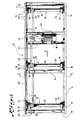
- Fig. 1: Eine Seitenansicht eines Längsabschnitts der Rollenbahn;
- Fig. 2: eine Draufsicht auf diesen Längsabschnitt der Rollenbahn, jedoch nach dem Entfernen von die Abdeckplatten bildenden Abdeckblechen, und
- Fig. 3: einen Schnitt nach der Linie 3-3 in Figur 2 durch die Rollenbahn, jedoch mit dem die Schnittebene durchsetzenden Abdeckblech.
- Fig. 1: A side view of a longitudinal section of the roller conveyor;
- 2: a plan view of this longitudinal section of the roller conveyor, but after the removal of the cover plates forming the cover plates, and
- 3: a section along the line 3-3 in Figure 2 through the roller conveyor, but with the cover plate passing through the cutting plane.
Ein als Ganzes mit 10 bezeichnetes Gestell der Rollenbahn besteht im wesentlichen aus auf einzeln höhenjustierbaren Füssen 12 stehenden seitlichen Längstragern 14 und Querträgern 16, die in gleichmässigen Abständen voneinander in Transportrichtung F hintereinander angeordnet und mit ihren Enden an den Längsträgern 14 befestigt sind. An den Längsträgern 14 sind in gleichen Abständen voneinander Lagervorrichtungen 18 angebracht, die der drehbaren Lagerung von als Ganzes mit 20 bezeichneten Antriebswellen dienen. Eine dieser Antriebswellen soll anhand der Figur 3 näher erläutert werden.A frame of the roller conveyor, designated as a whole by 10, essentially consists of lateral
Erfindungsgemäss besitzt die Antriebswelle einen Wellenschaft 22, auf dem im Abstand voneinander zwei Tragrollen 24 und 26 befestigt sind. Erfindungsgemäss entspricht die Breite einer jeden Tragrolle 24,26 der Breite einer der gestrichelt angedeuteten Kufen 28 der im übrigen nicht dargestellten Transportschlitten, der Mittenabstand A der beiden Tragrollen 24 und 26 voneinander ist gleich dem Mittenabstand der Kufen 28 bzw. derjenigen Bereiche der Transportschlitten, mit denen diese auf den Tragrollen aufliegen, und abgesehen von im folgenden noch zu erörternden Teilen der Antriebswellen 20 hat der Wellenschaft 22 überall einen wesentlich kleineren Durchmesser als die Tragrollen 24 und 26.According to the invention, the drive shaft has a
Zwischen den Tragrollen 24 und 26, und zwar einer der beiden Tragrollen benachbart, sind auf dem Wellenschaft 22 zwei Zahnscheiben 30 und 32 befestigt, während den Aussenseiten der Tragrollen 24 und 26 benachbart auf dem Wellenschaft 22 jeweils ein Spurkranz 34 fest angebracht ist. Wie die Figur 3 erkennen lässt, ist es nur erforderlich, den Durchmesser des Wellenschafts 22 zwischen den beiden Tragrollen 24 und 26 und insbesondere zwischen der Zahnscheibe 32 und der Tragrolle 26 wesentlich kleiner zu wählen als den Durchmesser der beiden Tragrollen 24, 26.Between the
Die Figur 2 zeigt einen elektrischen Getriebemotor 40, auf dessen Abtriebswelle zwei Zahnscheiben 42 und 44 befestigt sind. Über diese verläuft jeweils ein Zahnriemen 46 bzw. 48, der auch über eine der Zahnscheiben 30 und 32 der benachbarten Antriebswellen 20 verläuft.FIG. 2 shows an electric geared
In gleicher Weise sind die einander unmittelbar benachbarten Antriebswellen 20 paarweise über Zahnriemen 46 bzw.In the same way, the
48 miteinander verbunden, so dass sich über den Getriebemotor 40 sämtliche Antriebswellen 20 antreiben lassen.48 connected to each other so that all
Vorteilhafterweise haben die Längsträger 14 ein ungefähr Z-förmiges Profil (sh. Figur 3), dessen oberer Schenkel auf einem Niveau etwas unterhalb der Kuppen der Tragrollen 24 und 26 liegt. Auf diesen Längsträger werden nun tafelförmige, an ihren seitlichen Längsrändern bei 50 und an ihren vorderen und hinteren (in Transportrichtung gesehen) Rändern bei 52 nach unten abgekantete Abdeckbleche 70 aufgelegt und an den oberen Schenkeln 14a der Längsträger 14, z.B. mittels Schrauben, befestigt. Diese Abdeckbleche stossen in Längsrichtung der Rollenbahn gegeneinander und ergeben so eine im wesentlichen lückenlose Abdeckung. Sie besitzen nur verhältnismässig kleine, fensterförmige Öffnungen 72 für den Durchtritt jeweils einer der Tragrollen 24, 26 sowie eines Spurkranzes 34. Die erfindungsgemäss verwendeten Zahnscheiben 30 und 32 lassen sich mit einem wesentlich kleineren Aussendurchmesser herstellen als Kettenzahnräder, so dass der Durchmesser einer Zahnscheibe mit über sie verlaufendem Zahnriemen wesentlich geringer als derjenige der Tragrollen ist, was sich bezüglich der Verwendung einer durchgehenden Abdeckung vorteilhaft auswirkt. Infolge des im Vergleich zu Kettenzahnrädern kleinen Durchmessers der Zahnscheiben 30, 32 verbleibt trotz der geringen Bauhöhe der erfindungsgemässen Rollenbahn unter den Abkantungen 52 noch Platz für die Zahnriemen 46.Advantageously, the
Wie sich insbesondere aus Fig. 3 ergibt, erstrecken sich die Abdeckplatten erfindungsgemäss über alle Bereiche der Antriebswellen, die zwischen den seitlichen Gestellrahmenschenkeln liegen.3, the cover plates according to the invention extend over all areas of the drive shafts that lie between the lateral frame frame legs.
Claims (2)
Applications Claiming Priority (4)
| Application Number | Priority Date | Filing Date | Title |
|---|---|---|---|
| DE3626515 | 1986-08-05 | ||
| DE3626515 | 1986-08-05 | ||
| DE3711697 | 1987-04-07 | ||
| DE19873711697 DE3711697A1 (en) | 1986-08-05 | 1987-04-07 | Roller conveyor for vehicle bodywork transport slides |
Publications (4)
| Publication Number | Publication Date |
|---|---|
| EP0255620A2 EP0255620A2 (en) | 1988-02-10 |
| EP0255620A3 EP0255620A3 (en) | 1988-10-12 |
| EP0255620B1 EP0255620B1 (en) | 1990-04-11 |
| EP0255620B2 true EP0255620B2 (en) | 1994-08-24 |
Family
ID=25846255
Family Applications (1)
| Application Number | Title | Priority Date | Filing Date |
|---|---|---|---|
| EP87109910A Expired - Lifetime EP0255620B2 (en) | 1986-08-05 | 1987-07-09 | Rollerway for conveyor dollies for motor vehicle bodies |
Country Status (3)
| Country | Link |
|---|---|
| EP (1) | EP0255620B2 (en) |
| DE (1) | DE3762228D1 (en) |
| ES (1) | ES1003073Y (en) |
Cited By (2)
| Publication number | Priority date | Publication date | Assignee | Title |
|---|---|---|---|---|
| CN103771076A (en) * | 2014-01-02 | 2014-05-07 | 机械工业第四设计研究院有限公司 | Novel double-side drive roller |
| DE10213621B4 (en) * | 2002-03-27 | 2020-03-19 | Dürr Systems Ag | Conveyor |
Families Citing this family (10)
| Publication number | Priority date | Publication date | Assignee | Title |
|---|---|---|---|---|
| DE4007707A1 (en) * | 1989-03-11 | 1990-09-20 | Duerr Gmbh & Co | Roller transporter for pallets - has common drive for rollers and with different speeds for different sections |
| DE3940231A1 (en) * | 1989-12-05 | 1991-06-06 | Duerr Gmbh & Co | CONVEYOR |
| FR2659301A1 (en) * | 1990-03-08 | 1991-09-13 | Syprim Air Ind Environnement | TRANSPORT INSTALLATION COMPRISING A BEARING CHANNEL CONSISTING OF MOTORIZED ROLLS OR ROLLS. |
| DE4126822A1 (en) * | 1991-08-14 | 1993-02-18 | Bleichert Foerderanlagen Gmbh | CARRYING ROLL FOR CONVEYOR SYSTEMS, ESPECIALLY SKIDING SYSTEMS |
| JP4169434B2 (en) * | 1999-05-14 | 2008-10-22 | 株式会社椿本チエイン | Storage conveyor for hybrid transport cart |
| ITMI20022525A1 (en) * | 2002-11-28 | 2004-05-29 | Geico Spa | MODULAR SYSTEM FOR HANDLING, PARTICULARLY |
| DE102004056404B4 (en) * | 2004-11-23 | 2019-05-09 | Dürr Systems Ag | dryer |
| DE102004061791A1 (en) | 2004-12-22 | 2006-07-06 | Dürr Systems GmbH | electrocoating |
| DE102006030334A1 (en) | 2006-06-30 | 2008-01-03 | Dürr Systems GmbH | Dryer module for dryer for coating system, especially for vehicle bodies, has dryer floor section joined to boundary wall section so as to be pivotable relative to dryer ceiling section |
| DE102006055297A1 (en) | 2006-11-23 | 2008-05-29 | Dürr Systems GmbH | Workpiece carrier for conveying a workpiece to be painted |
Family Cites Families (6)
| Publication number | Priority date | Publication date | Assignee | Title |
|---|---|---|---|---|
| DE7244015U (en) * | 1973-05-30 | Krause J | Transport track with housing, especially friction roller conveyor | |
| DE528036C (en) * | 1929-05-30 | 1931-06-25 | Fried Krupp Grusonwerk Akt Ges | Roller table with individual electric drive of the rollers |
| US3857473A (en) * | 1972-06-05 | 1974-12-31 | Kornylac Co | Powered rail conveyor |
| US4185735A (en) * | 1977-09-15 | 1980-01-29 | Hammond Theodore A | Powered pan conveyor |
| EP0009508A1 (en) * | 1978-09-25 | 1980-04-16 | Carl Schenck Ag | Conveyor roller |
| DE3401634A1 (en) * | 1984-01-19 | 1985-07-25 | LSW Maschinenfabrik GmbH, 2800 Bremen | FRICTION ROLLER RAILWAY WITH FRICTION BETWEEN LENGTH SHAFT AND CROSS SHAFTS |
-
1987
- 1987-07-09 DE DE8787109910T patent/DE3762228D1/en not_active Expired - Lifetime
- 1987-07-09 EP EP87109910A patent/EP0255620B2/en not_active Expired - Lifetime
- 1987-08-05 ES ES19878702623U patent/ES1003073Y/en not_active Expired
Cited By (3)
| Publication number | Priority date | Publication date | Assignee | Title |
|---|---|---|---|---|
| DE10213621B4 (en) * | 2002-03-27 | 2020-03-19 | Dürr Systems Ag | Conveyor |
| CN103771076A (en) * | 2014-01-02 | 2014-05-07 | 机械工业第四设计研究院有限公司 | Novel double-side drive roller |
| CN103771076B (en) * | 2014-01-02 | 2016-05-04 | 机械工业第四设计研究院有限公司 | A kind of novel bilateral driving roller |
Also Published As
| Publication number | Publication date |
|---|---|
| ES1003073U (en) | 1988-07-01 |
| DE3762228D1 (en) | 1990-05-17 |
| EP0255620A3 (en) | 1988-10-12 |
| ES1003073Y (en) | 1989-02-16 |
| EP0255620A2 (en) | 1988-02-10 |
| EP0255620B1 (en) | 1990-04-11 |
Similar Documents
| Publication | Publication Date | Title |
|---|---|---|
| DE2045028C3 (en) | Apron conveyor | |
| EP0255620B2 (en) | Rollerway for conveyor dollies for motor vehicle bodies | |
| CH624075A5 (en) | ||
| DE3119529A1 (en) | "DEVICE FOR PRODUCING CHIPBOARD PLANTS, FIBER PANEL PLANTS AND THE LIKE PRESS COVERAGES" | |
| DE3607730A1 (en) | ADAPTABLE CONVEYOR | |
| EP0434862B1 (en) | Lifting device, especially for conveyors | |
| EP0293625A2 (en) | Conveyor for cuttings | |
| DE2809613C2 (en) | ||
| DE3711697A1 (en) | Roller conveyor for vehicle bodywork transport slides | |
| DE4109631B4 (en) | Lift table for overcoming a jump in height in conveyor lines | |
| EP0377775A1 (en) | Conveyor belt | |
| DE2943066C2 (en) | Caterpillar drive | |
| DE2745875C2 (en) | ||
| EP0489278A1 (en) | Belt conveyor | |
| EP0112464B1 (en) | Tensioning device for scraper flight conveyors or similar conveyors or agricultural vehicles and machines | |
| DE3152911C2 (en) | Continuously operating press for pressing chipboard sheets, fibreboard sheets and similar sheets of pressed material | |
| DE2050860A1 (en) | Device for harvesting cabbages | |
| DE2166212A1 (en) | HINGE BELT CONVEYOR FOR METAL SPRINGS. REMOVAL FROM: 2100932 | |
| DE2018199C3 (en) | Device for the continuous production of rigid foam panels laminated with flexible foils, in particular based on polyurethane | |
| AT401506B (en) | SORTING DEVICE WITH AN ENDLESS LINK CONVEYOR | |
| CH664342A5 (en) | Variable length conveyor for bulk-carrying vehicle - has endless belt over telescopic slides with servo-driven extension | |
| DE1965312A1 (en) | Sponsor | |
| DE4206939C1 (en) | ||
| DE19632376A1 (en) | Corner station for belt conveyor | |
| DE4431836A1 (en) | Transfer mechanism for parts from first to second conveyor track |
Legal Events
| Date | Code | Title | Description |
|---|---|---|---|
| PUAI | Public reference made under article 153(3) epc to a published international application that has entered the european phase |
Free format text: ORIGINAL CODE: 0009012 |
|
| AK | Designated contracting states |
Kind code of ref document: A2 Designated state(s): BE DE FR SE |
|
| PUAL | Search report despatched |
Free format text: ORIGINAL CODE: 0009013 |
|
| AK | Designated contracting states |
Kind code of ref document: A3 Designated state(s): BE DE FR SE |
|
| 17P | Request for examination filed |
Effective date: 19890407 |
|
| 17Q | First examination report despatched |
Effective date: 19890810 |
|
| GRAA | (expected) grant |
Free format text: ORIGINAL CODE: 0009210 |
|
| AK | Designated contracting states |
Kind code of ref document: B1 Designated state(s): BE DE FR SE |
|
| REF | Corresponds to: |
Ref document number: 3762228 Country of ref document: DE Date of ref document: 19900517 |
|
| ET | Fr: translation filed | ||
| PLBI | Opposition filed |
Free format text: ORIGINAL CODE: 0009260 |
|
| PLBI | Opposition filed |
Free format text: ORIGINAL CODE: 0009260 |
|
| PLAB | Opposition data, opponent's data or that of the opponent's representative modified |
Free format text: ORIGINAL CODE: 0009299OPPO |
|
| 26 | Opposition filed |
Opponent name: MERCEDES- BENZ AG Effective date: 19901221 |
|
| 26 | Opposition filed |
Opponent name: CARL SCHENCK AG Effective date: 19910110 Opponent name: MANNESMANN AKTIENGESELLSCHAFT Effective date: 19910109 Opponent name: BLEICHERT FOERDERANLAGEN GMBH, Effective date: 19901227 Opponent name: MERCEDES- BENZ AG Effective date: 19901221 |
|
| R26 | Opposition filed (corrected) |
Opponent name: MERCEDES- BENZ AG Effective date: 19901221 |
|
| PUAA | Information related to the publication of a b2 document modified |
Free format text: ORIGINAL CODE: 0009299PMAP |
|
| PUAH | Patent maintained in amended form |
Free format text: ORIGINAL CODE: 0009272 |
|
| STAA | Information on the status of an ep patent application or granted ep patent |
Free format text: STATUS: PATENT MAINTAINED AS AMENDED |
|
| 27A | Patent maintained in amended form |
Effective date: 19940824 |
|
| AK | Designated contracting states |
Kind code of ref document: B2 Designated state(s): SE |
|
| R27A | Patent maintained in amended form (corrected) |
Effective date: 19940824 |
|
| ET3 | Fr: translation filed ** decision concerning opposition | ||
| EAL | Se: european patent in force in sweden |
Ref document number: 87109910.7 |
|
| APAC | Appeal dossier modified |
Free format text: ORIGINAL CODE: EPIDOS NOAPO |
|
| APAC | Appeal dossier modified |
Free format text: ORIGINAL CODE: EPIDOS NOAPO |
|
| APAH | Appeal reference modified |
Free format text: ORIGINAL CODE: EPIDOSCREFNO |
|
| PGFP | Annual fee paid to national office [announced via postgrant information from national office to epo] |
Ref country code: FR Payment date: 20060612 Year of fee payment: 20 |
|
| PGFP | Annual fee paid to national office [announced via postgrant information from national office to epo] |
Ref country code: SE Payment date: 20060622 Year of fee payment: 20 |
|
| PGFP | Annual fee paid to national office [announced via postgrant information from national office to epo] |
Ref country code: BE Payment date: 20060630 Year of fee payment: 20 |
|
| PGFP | Annual fee paid to national office [announced via postgrant information from national office to epo] |
Ref country code: DE Payment date: 20060711 Year of fee payment: 20 |
|
| EUG | Se: european patent has lapsed | ||
| BE20 | Be: patent expired |
Owner name: *DURR G.M.B.H. Effective date: 20070709 |
|
| PLAB | Opposition data, opponent's data or that of the opponent's representative modified |
Free format text: ORIGINAL CODE: 0009299OPPO |