EP0254036A2 - Procédé et installation pour la réduction de NOx contenu dans les fumées des générateurs de vapeur brûlant la poussière de charbon avec l'élimination sèche de la cendre - Google Patents
Procédé et installation pour la réduction de NOx contenu dans les fumées des générateurs de vapeur brûlant la poussière de charbon avec l'élimination sèche de la cendre Download PDFInfo
- Publication number
- EP0254036A2 EP0254036A2 EP87108791A EP87108791A EP0254036A2 EP 0254036 A2 EP0254036 A2 EP 0254036A2 EP 87108791 A EP87108791 A EP 87108791A EP 87108791 A EP87108791 A EP 87108791A EP 0254036 A2 EP0254036 A2 EP 0254036A2
- Authority
- EP
- European Patent Office
- Prior art keywords
- air
- line
- burner
- flue gas
- fresh air
- Prior art date
- Legal status (The legal status is an assumption and is not a legal conclusion. Google has not performed a legal analysis and makes no representation as to the accuracy of the status listed.)
- Withdrawn
Links
Images
Classifications
-
- F—MECHANICAL ENGINEERING; LIGHTING; HEATING; WEAPONS; BLASTING
- F23—COMBUSTION APPARATUS; COMBUSTION PROCESSES
- F23C—METHODS OR APPARATUS FOR COMBUSTION USING FLUID FUEL OR SOLID FUEL SUSPENDED IN A CARRIER GAS OR AIR
- F23C9/00—Combustion apparatus characterised by arrangements for returning combustion products or flue gases to the combustion chamber
- F23C9/003—Combustion apparatus characterised by arrangements for returning combustion products or flue gases to the combustion chamber for pulverulent fuel
-
- B—PERFORMING OPERATIONS; TRANSPORTING
- B01—PHYSICAL OR CHEMICAL PROCESSES OR APPARATUS IN GENERAL
- B01D—SEPARATION
- B01D53/00—Separation of gases or vapours; Recovering vapours of volatile solvents from gases; Chemical or biological purification of waste gases, e.g. engine exhaust gases, smoke, fumes, flue gases, aerosols
- B01D53/34—Chemical or biological purification of waste gases
- B01D53/46—Removing components of defined structure
- B01D53/54—Nitrogen compounds
- B01D53/56—Nitrogen oxides
Definitions
- the invention relates to a method and a system for reducing the NO x content in the flue gas during the combustion of coal dust in steam boiler systems, in particular with dry ash removal, preferably in large combustion systems of steam boilers, in which part of the flue gases in the area of the burners are returned to the combustion chamber and is mixed with fresh air before entering the boiler.
- a reduction in the NO x content in the exhaust gas flow entering the environment can in principle be achieved by direct measures on the furnace, so-called primary measures, or by downstream flue gas cleaning systems, so-called secondary measures.
- the object of the invention is to provide a solution which largely eliminates the NO x content in the exhaust gas stream escaping into the environment in coal-dust-fired steam boiler systems by means of primary-side measures which require a relatively small amount of space and have a low loss of efficiency and which in particular enable inexpensive retrofitting of existing systems reduced.
- this object is achieved according to the invention in that in at least two superimposed burner levels, the flame cores in the burner core areas are acted upon with primary air in a substoichiometric ratio to the respective coal dust flow and, if appropriate, admixable fresh air and / or recirculated cold flue gas Burner core areas are additionally supplied as secondary air and the burner jacket areas as tertiary air in such a way that an almost stoichiometric combustion air ratio arises in the area of the lower burner level and a strongly substoichiometric combustion air ratio in the area of the upper burner level.
- the method according to the invention By means of the method according to the invention, such a low NO x content can be set in the exhaust gas stream emerging into the environment that the limit values of the large combustion plant ordinance can be complied with if necessary solely through the measures according to the invention on the primary side.
- the method according to the invention is suitable for retrofitting existing systems, since it provides measures which are structurally simple and take up relatively little space, does not have a significant loss in efficiency due to the relatively small amount of recirculated flue gas, and can therefore be produced cost-effectively with a relatively small investment.
- the low NO x content in the flue gas is achieved in the method according to the invention by the advantageous combination of various measures.
- the substoichiometric mode of operation of the flame cores in the burner core areas and the additional secondary air supplied - possibly admixable fresh air and / or recirculated cold flue gas - mean that relatively little thermal NO x is produced in the burner core areas.
- Tertiary air - a mixture of recirculated cold flue gas and admixed fresh air - is then fed to the burner jacket areas for post-combustion, with the recirculated cold flue gas delaying post-combustion at a relatively low flame temperature is achieved.
- the invention provides in a further development that reducing gas is additionally injected into the combustion chamber above the upper burner level and a further air stream, in particular cold air, is blown into the combustion chamber as upper air above the reduction gas injection.
- Cold air is to be understood here as the fresh air removed from the environment of a plant operating according to the method of the invention, which is not supplied to any air preheater.
- the invention provides that a different mixture of recirculated cold flue gas and fresh air is fed to the burner core areas as secondary air per level and the jacket areas as tertiary air per level, the secondary air for the upper burner level possibly consisting only of recirculated flue gas. This measure is particularly useful for setting the different combustion air conditions in the combustion planes.
- An advantageous flue gas flow results when a first partial stream of the recirculated flue gas is fed to the burner jacket areas after fresh air admixture, a second partial stream of the recirculated flue gas stream downstream of an air preheater into the fresh air stream Secondary air for the burner core areas is injected and a third partial flow of the recirculated flue gas downstream of a branching of the secondary air supply for the lower and the upper burner level is injected into the mixture of second partial flow of recirculated flue gas and fresh air, as the invention provides in a further embodiment.
- the invention provides that 15-30%, in particular 27%, of the flue gas leaving the boiler is recirculated and 5-10%, in particular 8%, of the recirculated flue gas is branched off into the second partial stream 5-15 %, in particular 11%, of the recirculated flue gas are branched off and 5-10%, in particular 8%, of the recirculated flue gas are branched off into the third sub-stream, the first sub-stream being 15-25%, in particular 22%, of the total fresh air to be supplied for formation mixed with the tertiary air and the second partial flow downstream of the air preheater is injected into a fresh air flow comprising 30-40%, in particular 33%, of the total fresh air supply.
- the invention provides in further development that further fresh air streams are branched off in front of and behind the air preheater, which flow with the coal dust to the flame cores as primary air are fed.
- the invention provides in an advantageous embodiment that natural gas is injected into the combustion chamber at high speed above the upper burner level and one of the above the reduction gas injection as Partial stream branching off the upper air to be blown in is blown into the combustion chamber as curtain air in the area of the upper burner levels.
- the effect of the method according to the invention on the reduction of NO x in the exhaust gas stream comes into play when the veil air is blown into the combustion chamber from all side walls of the boiler, but the other media only come into the combustion chamber via the Burner front wall are fed.
- the invention provides that, if there are more than two burner levels one above the other, these are effectively connected either to a lower and an upper burner level or in each case two burner levels directly one above the other to a lower and an upper burner level, the combustion air ratio at least tending to decrease from an almost stoichiometric operating mode in the lower first burner level towards the upper last one.
- the mode of operation of the method according to the invention can be set more precisely by varying the fresh air / flue gas ratios, in particular in the secondary air flows to the individual burner levels, the greater the number of burner levels.
- the invention provides a system which consists of a combustion chamber with at least two burner levels one above the other, a branch line for a partial flue gas flow, a line for a first partial flow of recirculated flue gas, which opens into a mixing chamber, a line for a Partial fresh air flow, which also opens into the mixing chamber, a line that feeds the mixture from the mixing chamber as tertiary air to the jacket areas of the burners in the burner levels, a line for a second partial flow of recirculated flue gas, which is injected into the heated fresh air Recirculated flue gas opens, which is arranged in a line for preheated fresh air, and a line branching into a line for the upper burner level and a line for the lower burner level, which connect the injection with the burner core areas, the line for the upper burner level another Injection is arranged, in which a line for a third partial flow of recirculated flue gas opens out.
- the invention provides in one embodiment that nozzle tubes are arranged concentrically around each burner for the supply of tertiary air in the jacket areas.
- the system has a reducing gas line that opens into the combustion chamber via injections above the upper burner level, an air line that opens into the combustion chamber via injections above the reducing gas injections, and a fresh air line that opens into the combustion chamber in the area of the upper burner level via further injections , on.
- nozzles for fresh air and only burners and nozzles for tertiary air, reducing gas and fresh air are arranged all around in the side walls of the combustion chamber, as provided by the invention in one embodiment.
- the air lines are connected by lines with a fresh air line and / or by lines to the line for preheated fresh air and the line for a partial fresh air flow through a line is connected to the line for preheated fresh air and / or by a line to the fresh air line, as the invention provides in a further embodiment.
- the invention provides in an expedient development that the system has a branch line from the fresh air line and / or a branch line from the line for preheated fresh air for at least partial supply to one of the burner core areas coal dust and primary air supply line with primary air.
- the tertiary air, upper air and Schleiertions streams are introduced with a high momentum of the individual flows into the combustion chamber, so that the invention provides in a further embodiment that in the line for tertiary air and the line for the upper - and Schleierluft booster blowers are arranged.
- system according to the invention is also characterized by perforation bands which are arranged all around in the combustion chamber walls at the end of the air duct in the region of the combustion chamber and form the further injections.
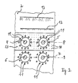
- the burner front wall 2 of a boiler is equipped with four coal dust burners 4, 5, 6 and 7, which are arranged in two burner levels one above the other - the upper burner level 8 and the lower burner level 9. Furthermore, the burners 4, 5, 6, 7 are arranged concentrically around each burner 4, 5, 6, 7 nozzle pipes 11 as well as reducing gas injections 12, injections 13 and further injections 14 in the burner front wall 2 in the jacket regions 10. The injections 14 are present in the area of the upper burner level 8 in the burner front wall 2 and also all around in the other combustion chamber walls.
- the boiler 3 may be a coal-fired steam boiler with dry ash removal.
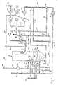
- the boiler 3 On the flue gas side, the boiler 3 has a flue gas line 15 which supplies flue gases to an air preheater 16. From the air preheater 16, the flue gases are fed to an electrostatic filter 18 via a line 17 - and then discharged into the environment via a chimney 19. The direction of flow of the respective medium is indicated by small arrows, as is the case with the other lines in this figure. Between the chimney 19 and the electrostatic filter 18 is a Suction 20 arranged.
- fresh air is drawn in via a blower 21 and fed via a line 22 to the air preheater 16, from which the fresh air is passed on in line 23 for preheated fresh air.
- preheated fresh air refers to the fresh air guided through an air preheater after the heat has been taken over. Otherwise there is talk of fresh air or cold fresh air, which then has an ambient temperature. Similarly, the flue gas passed through the air preheater is referred to as cold flue gas after the heat has been given off.
- a branch line 24 branches off from the flue gas line 17, in the course of which a dust separator 25 and a blower 26 are arranged. Downstream of the blower 26, the branch line 24 branches into a line 27 for a first partial flow of recirculated flue gas, which opens into a mixing chamber 28, a line 29 for a second partial flow of recirculated flue gas, which opens into an injection 30, and a line 31 for one third partial flow of recirculated flue gas, which opens into an injection 32.
- a line 33 for a partial fresh air flow opens into the mixing chamber 28 and is connected via a line 34 to the line 23 for preheated fresh air and the line 35 to the fresh air line 22.
- the supply of fresh air into the line 33 can be such that the line 33 through the line 34 either only preheated fresh air or through the line 35 only cold fresh air or a mixture of preheated and cold fresh air is supplied when both lines are opened.
- the mixture passes through a line 36 into the nozzle pipes 11 in the jacket regions 10 of the burners 4, 5, 6, 7, where this mixture is blown into the combustion chamber 1 as so-called tertiary air.
- a pressure increasing fan 37 is arranged in the line 36.
- a partial flue gas stream is injected into the line 23 for preheated fresh air and this mixture is fed through the line 40 branching into a line 38 for the upper burner level and a line 39 for the lower burner level to the burner core areas as secondary air.
- the partial amount of flue gas to be supplied to the lines 38 and 39 can be controlled by means of regulating elements (not shown in detail), so that, if necessary, the entire gas mixture passed through line 40 can be fed to line 39 and then to line 38 only via the injection 32 arranged therein through the line 31 a partial flue gas stream is supplied.
- the flue gas recirculated in lines 24, 27, 29, 31 is so-called cold flue gas because it is branched off from flue gas line 17 downstream of air preheater 16.
- Natural gas is supplied to the injections 12 through a reducing gas line 41.
- the amount of natural gas injected here contributes up to 10% to the amount of fuel required for the combustion heat output of the boiler.
- the nozzles 13 are connected by means of an air line 42 for blowing in so-called upper air and the further nozzles 14 are connected to a line 44 in which a pressure-increasing blower 45 is arranged by means of a fresh air line 43.
- a branch line 46 opens into the line 44 and is connected to the fresh air line 22 via a line 47 and to the line 23 for preheated fresh air via a line 48.
- the air supply in line 46 can be regulated such that either only fresh air from the fresh air line 22 through line 47 or only preheated fresh air from line 23 through line 48 or a mixture of fresh air and preheated fresh air or no air at all is supplied. In the latter case line 44 is then supplied with air through line 49.
- a branching line 50 supplies the core areas of the burners 4, 5, 6, 7 with coal dust and primary air.
- a branch line 51 is arranged in the fresh air line 22 and a branch line 52, also indicated as an arrow, is arranged in the line 23 for the preheated fresh air, both of which open into the line 50 in a manner not shown here.
- Perforation bands 53 arranged all around in the combustion chamber 1 in the combustion chamber walls of the boiler 3 form the injections 14, via which a partial air flow is injected into the combustion chamber 1 as so-called fog air.
- the partial view of the burner front wall according to FIG. 2 shows this arrangement schematically for the area of the burner front wall.
- the air flow injected through the line 43 is to be kept as low as possible.
- FIG. 1 shows a not necessarily sufficient number of different actuating, regulating and flow measuring devices in different lines not specified here. This is not important in the context of the present invention.
- the described embodiment can be modified in many ways without departing from the basic idea of the invention.
- the method shown here can be used not only for coal dust-fired boiler systems with front lighting, but also for corner or box firing. Possibly. the cold top and / or curtain air can also be replaced by preheated air.
- the method can also be used on melting chamber boilers.
Landscapes
- Engineering & Computer Science (AREA)
- Chemical & Material Sciences (AREA)
- Health & Medical Sciences (AREA)
- Biomedical Technology (AREA)
- Environmental & Geological Engineering (AREA)
- Analytical Chemistry (AREA)
- General Chemical & Material Sciences (AREA)
- Oil, Petroleum & Natural Gas (AREA)
- Chemical Kinetics & Catalysis (AREA)
- Combustion & Propulsion (AREA)
- Mechanical Engineering (AREA)
- General Engineering & Computer Science (AREA)
Applications Claiming Priority (2)
| Application Number | Priority Date | Filing Date | Title |
|---|---|---|---|
| DE19863621347 DE3621347A1 (de) | 1986-06-26 | 1986-06-26 | Verfahren und anlage zur verminderung des no(pfeil abwaerts)x(pfeil abwaerts)-gehaltes im rauchgas bei kohlenstaubbefeuerten dampferzeugern mit trockenentaschung |
| DE3621347 | 1986-06-26 |
Publications (2)
| Publication Number | Publication Date |
|---|---|
| EP0254036A2 true EP0254036A2 (fr) | 1988-01-27 |
| EP0254036A3 EP0254036A3 (fr) | 1989-04-26 |
Family
ID=6303705
Family Applications (1)
| Application Number | Title | Priority Date | Filing Date |
|---|---|---|---|
| EP87108791A Withdrawn EP0254036A3 (fr) | 1986-06-26 | 1987-06-19 | Procédé et installation pour la réduction de NOx contenu dans les fumées des générateurs de vapeur brûlant la poussière de charbon avec l'élimination sèche de la cendre |
Country Status (3)
| Country | Link |
|---|---|
| US (1) | US4739713A (fr) |
| EP (1) | EP0254036A3 (fr) |
| DE (1) | DE3621347A1 (fr) |
Cited By (4)
| Publication number | Priority date | Publication date | Assignee | Title |
|---|---|---|---|---|
| EP0497089A3 (en) * | 1991-02-01 | 1992-12-23 | Noell-K+K Abfalltechnik Gmbh | Temperature regulation method for incineration plants |
| FR2711224A1 (fr) * | 1993-10-12 | 1995-04-21 | Guillot Ind Sa | Dispositif de chauffage à recyclage partiel des gaz de combustion. |
| WO1998054513A1 (fr) * | 1997-05-27 | 1998-12-03 | Aventis Research & Technologies Gmbh & Co Kg | PROCEDE POUR LA COMBUSTION FAIBLE EN NOx DE HOUILLE DANS DES GENERATEURS DE VAPEUR DE CENDRES A SEC |
| CN106765149A (zh) * | 2017-01-13 | 2017-05-31 | 安徽未名鼎和环保有限公司 | 一种高效能量利用的垃圾焚烧系统 |
Families Citing this family (44)
| Publication number | Priority date | Publication date | Assignee | Title |
|---|---|---|---|---|
| DE3825291A1 (de) * | 1988-07-26 | 1990-02-01 | Ver Kesselwerke Ag | Verfahren und feuerungsanlage zur verbrennung fossiler brennstoffe unter reduzierter bildung von stickoxiden |
| DE3839922A1 (de) * | 1988-11-26 | 1990-05-31 | Henkel Kgaa | Verfahren und vorrichtung zur behandlung von kohlenstoffhaltigem flugstaub in rauchgasen |
| CA2018910C (fr) * | 1989-06-16 | 2000-02-22 | Masaaki Furukawa | Mode de controle de la combustion a l'interieur d'un four |
| JPH08503060A (ja) * | 1992-11-17 | 1996-04-02 | アパラーテバウ ローテミューレ ブラント ウント クリッツラー ゲゼルシャフト ミット ベシュレンクテル ハフツング | 燃焼設備 |
| US6837702B1 (en) | 1994-12-01 | 2005-01-04 | Wartsila Diesel, Inc. | Method of operating a combined cycle power plant |
| US5525053A (en) * | 1994-12-01 | 1996-06-11 | Wartsila Diesel, Inc. | Method of operating a combined cycle power plant |
| US5546874A (en) * | 1994-12-22 | 1996-08-20 | Duquesne Light Company | Low nox inter-tube burner for roof-fired furnaces |
| US5678498A (en) * | 1995-10-11 | 1997-10-21 | Envirotech, Inc. | Process and apparatus for ventless combustion of waste |
| US5759022A (en) * | 1995-10-16 | 1998-06-02 | Gas Research Institute | Method and system for reducing NOx and fuel emissions in a furnace |
| US5730070A (en) * | 1995-12-22 | 1998-03-24 | Combustion Engineering, Inc. | Apparatus for introducing gas recirculation to control steam temperature in steam generation systems |
| DE19652967C1 (de) * | 1996-12-19 | 1998-04-09 | Sbw Sonderabfallentsorgung Bad | Feuerbestattungseinrichtung |
| DE19724929B4 (de) * | 1997-06-12 | 2007-04-12 | Fritz Dr.-Ing. Schoppe | Brennverfahren für Staubfeuerungen kleiner Leistung |
| US6206949B1 (en) * | 1997-10-29 | 2001-03-27 | Praxair Technology, Inc. | NOx reduction using coal based reburning |
| US20080286704A1 (en) * | 1998-11-18 | 2008-11-20 | Hermann Bruggendick | Method of burning a nitrogen-containing fuel |
| US6604474B2 (en) * | 2001-05-11 | 2003-08-12 | General Electric Company | Minimization of NOx emissions and carbon loss in solid fuel combustion |
| US6453829B1 (en) * | 2001-10-01 | 2002-09-24 | Wu Chin Tsai | Incinerator assembly having waste smoke treating device |
| US20030175634A1 (en) * | 2002-03-16 | 2003-09-18 | George Stephens | Burner with high flow area tip |
| US6887068B2 (en) | 2002-03-16 | 2005-05-03 | Exxonmobil Chemical Patents Inc. | Centering plate for burner |
| US6866502B2 (en) | 2002-03-16 | 2005-03-15 | Exxonmobil Chemical Patents Inc. | Burner system employing flue gas recirculation |
| US6869277B2 (en) * | 2002-03-16 | 2005-03-22 | Exxonmobil Chemical Patents Inc. | Burner employing cooled flue gas recirculation |
| US6893251B2 (en) | 2002-03-16 | 2005-05-17 | Exxon Mobil Chemical Patents Inc. | Burner design for reduced NOx emissions |
| US6881053B2 (en) * | 2002-03-16 | 2005-04-19 | Exxonmobil Chemical Patents Inc. | Burner with high capacity venturi |
| US6846175B2 (en) * | 2002-03-16 | 2005-01-25 | Exxonmobil Chemical Patents Inc. | Burner employing flue-gas recirculation system |
| US6986658B2 (en) | 2002-03-16 | 2006-01-17 | Exxonmobil Chemical Patents, Inc. | Burner employing steam injection |
| US6890172B2 (en) | 2002-03-16 | 2005-05-10 | Exxonmobil Chemical Patents Inc. | Burner with flue gas recirculation |
| US6902390B2 (en) * | 2002-03-16 | 2005-06-07 | Exxonmobil Chemical Patents, Inc. | Burner tip for pre-mix burners |
| EP1488172B1 (fr) * | 2002-03-16 | 2010-10-13 | ExxonMobil Chemical Patents Inc. | Bouchon amovible de port d'allumage destine a etre employe dans des bruleurs |
| US20030175635A1 (en) * | 2002-03-16 | 2003-09-18 | George Stephens | Burner employing flue-gas recirculation system with enlarged circulation duct |
| US6893252B2 (en) | 2002-03-16 | 2005-05-17 | Exxonmobil Chemical Patents Inc. | Fuel spud for high temperature burners |
| US7322818B2 (en) * | 2002-03-16 | 2008-01-29 | Exxonmobil Chemical Patents Inc. | Method for adjusting pre-mix burners to reduce NOx emissions |
| AU2003225834A1 (en) * | 2002-03-16 | 2003-10-08 | Exxonmobil Chemical Patents Inc. | Improved burner with low nox emissions |
| JP2004205161A (ja) * | 2002-12-26 | 2004-07-22 | Hitachi Ltd | 固体燃料ボイラ及びボイラ燃焼方法 |
| US7374735B2 (en) * | 2003-06-05 | 2008-05-20 | General Electric Company | Method for nitrogen oxide reduction in flue gas |
| DE102005001907B4 (de) * | 2005-01-14 | 2007-05-10 | Steinmüller Engineering GmbH | Verfahren und Anlage zur Verbrennung eines Brennstoffs |
| US7350471B2 (en) * | 2005-03-01 | 2008-04-01 | Kalex Llc | Combustion system with recirculation of flue gas |
| US8087248B2 (en) * | 2008-10-06 | 2012-01-03 | Kalex, Llc | Method and apparatus for the utilization of waste heat from gaseous heat sources carrying substantial quantities of dust |
| US8695344B2 (en) * | 2008-10-27 | 2014-04-15 | Kalex, Llc | Systems, methods and apparatuses for converting thermal energy into mechanical and electrical power |
| US8176738B2 (en) | 2008-11-20 | 2012-05-15 | Kalex Llc | Method and system for converting waste heat from cement plant into a usable form of energy |
| US8474263B2 (en) | 2010-04-21 | 2013-07-02 | Kalex, Llc | Heat conversion system simultaneously utilizing two separate heat source stream and method for making and using same |
| US20120244479A1 (en) * | 2011-03-22 | 2012-09-27 | General Electric Company | Combustion System Using Recycled Flue Gas to Boost Overfire Air |
| US8833077B2 (en) | 2012-05-18 | 2014-09-16 | Kalex, Llc | Systems and methods for low temperature heat sources with relatively high temperature cooling media |
| CN106545865B (zh) * | 2017-01-13 | 2018-11-13 | 安徽未名鼎和环保有限公司 | 一种气、固高效循环的垃圾燃烧系统 |
| JP6853053B2 (ja) * | 2017-01-31 | 2021-03-31 | 三菱パワー株式会社 | ボイラシステム、および、ボイラシステムの運転方法 |
| JP6978879B2 (ja) * | 2017-09-08 | 2021-12-08 | 三菱パワー株式会社 | ボイラの空気送給システム |
Family Cites Families (11)
| Publication number | Priority date | Publication date | Assignee | Title |
|---|---|---|---|---|
| GB1274637A (en) * | 1969-03-27 | 1972-05-17 | Zink Co John | Process for disposal of oxides of nitrogen |
| NL7502523A (nl) * | 1975-03-04 | 1976-09-07 | Zink Co John | Werkwijze voor het omzetten van gassen die stik- stofoxyden bevatten. |
| US4144017A (en) * | 1976-11-15 | 1979-03-13 | The Babcock & Wilcox Company | Pulverized coal combustor |
| US4294178A (en) * | 1979-07-12 | 1981-10-13 | Combustion Engineering, Inc. | Tangential firing system |
| JPS5623615A (en) * | 1979-08-06 | 1981-03-06 | Babcock Hitachi Kk | Burning method for low nox |
| GB2076135B (en) * | 1980-04-22 | 1984-04-18 | Mitsubishi Heavy Ind Ltd | Pulverized fuel firing apparatus |
| DE3021875C2 (de) * | 1980-06-11 | 1985-04-25 | L. & C. Steinmüller GmbH, 5270 Gummersbach | Verfahren zur Anwendung der selektiven Reduktion von Stickoxiden aus einer Flammenverbrennung mit Hilfe von Ammoniak |
| US4511325A (en) * | 1982-03-05 | 1985-04-16 | Coen Company, Inc. | System for the reduction of NOx emissions |
| US4438709A (en) * | 1982-09-27 | 1984-03-27 | Combustion Engineering, Inc. | System and method for firing coal having a significant mineral content |
| DE3441675A1 (de) * | 1984-11-15 | 1986-05-22 | L. & C. Steinmüller GmbH, 5270 Gummersbach | Verfahren zur verringerung des no(pfeil abwaerts)x(pfeil abwaerts)-gehalts in verbrennungsgasen |
| DE3501189A1 (de) * | 1985-01-16 | 1986-07-17 | Henkel KGaA, 4000 Düsseldorf | Verfahren und anlage zur reduzierung des no(pfeil abwaerts)x(pfeil abwaerts)-gehaltes von mittels fossiler brennstoffe beheizten grossfeuerungsanlagen |
-
1986
- 1986-06-26 DE DE19863621347 patent/DE3621347A1/de active Granted
-
1987
- 1987-06-19 EP EP87108791A patent/EP0254036A3/fr not_active Withdrawn
- 1987-06-26 US US07/067,517 patent/US4739713A/en not_active Expired - Fee Related
Cited By (4)
| Publication number | Priority date | Publication date | Assignee | Title |
|---|---|---|---|---|
| EP0497089A3 (en) * | 1991-02-01 | 1992-12-23 | Noell-K+K Abfalltechnik Gmbh | Temperature regulation method for incineration plants |
| FR2711224A1 (fr) * | 1993-10-12 | 1995-04-21 | Guillot Ind Sa | Dispositif de chauffage à recyclage partiel des gaz de combustion. |
| WO1998054513A1 (fr) * | 1997-05-27 | 1998-12-03 | Aventis Research & Technologies Gmbh & Co Kg | PROCEDE POUR LA COMBUSTION FAIBLE EN NOx DE HOUILLE DANS DES GENERATEURS DE VAPEUR DE CENDRES A SEC |
| CN106765149A (zh) * | 2017-01-13 | 2017-05-31 | 安徽未名鼎和环保有限公司 | 一种高效能量利用的垃圾焚烧系统 |
Also Published As
| Publication number | Publication date |
|---|---|
| DE3621347A1 (de) | 1988-01-14 |
| US4739713A (en) | 1988-04-26 |
| DE3621347C2 (fr) | 1989-06-01 |
| EP0254036A3 (fr) | 1989-04-26 |
Similar Documents
| Publication | Publication Date | Title |
|---|---|---|
| DE3621347C2 (fr) | ||
| EP0191141B1 (fr) | Procédé et installation pour la réduction de la teneur en NOx dans le gaz brûlé lors de la combustion de combustibles fossiles dans des installations de chauffage | |
| DE69107857T2 (de) | Feuerungssystem mit mehrfachbrennern und mit tangentialer luftzufuhr konzentrisch zum zentralteil des feuerraumes. | |
| DE2615369C3 (de) | Verfahren zur Rauchgaskonditionierung in Abfallverbrennungsanlagen mit Wärmeverwertung, insbesondere für kommunalen und industriellen Müll, und Vorrichtung zur Durchführung des Verfahrens | |
| DE69608140T2 (de) | Methode und vorrichtung zur verwendung von biobrennstoff oder abfallmaterial in der energieproduktion | |
| DE3532281C2 (de) | Verfahren und anlage zur beeinflussung der abgase eines wirbelbettkessels | |
| DE69923797T2 (de) | Verfahren zum betrieb eines tangentialen feuerungssystems | |
| DE69111058T2 (de) | Verfahren zur Verminderung des Ausstosses von Distickstoffoxid bei der Verbrennung von stickstoffhaltigem Brennstoff in Wirbelschichtreaktoren. | |
| DE3048201C2 (fr) | ||
| WO2010102736A1 (fr) | Installation destinée à sécher des copeaux de bois et procédé associé pour sécher des copeaux de bois | |
| DE69420051T2 (de) | System mit niedrigem ausstoss und mit niedrigem luftüberschuss | |
| EP0132584B1 (fr) | Procédé et installation pour diminuer l'émission de la matière nocive dans les gaz d'échappement des installations de combustion | |
| EP0607210A1 (fr) | Procede pour la combustion de matieres solides. | |
| DE2738722A1 (de) | Verfahren und vorrichtung zur vermeidung der bildung von stickoxiden | |
| EP0302910B1 (fr) | Combustion de charbon avec un foyer a lit fluidise | |
| DE3751733T2 (de) | Verfahren und Vorrichtung, um Schwefeldioxyd in Rauchgasen zu reduzieren | |
| DE3326100C2 (de) | Verfahren und Anlage zum Vermindern der Stickoxydemission in Rauchgasen von Feuerungsanlagen | |
| DE3503603A1 (de) | Feuerungsanlage | |
| DE3731082C1 (en) | Method and plant for obtaining energy from solid, high-ballast fuels | |
| EP0496856B1 (fr) | Procédé et dispositif de desulfuration complet à sec de gaz de combustion contenant du SO2 et des poussières | |
| EP0690263A2 (fr) | Procédé pour le fonctionnement d'une installation de combustion | |
| DE3331545C2 (fr) | ||
| DE3825291A1 (de) | Verfahren und feuerungsanlage zur verbrennung fossiler brennstoffe unter reduzierter bildung von stickoxiden | |
| DE69527288T2 (de) | Feuerung mit Brenneranlage und Verbrennungsverfahren mit niedriger Stickstoffoxyderzeugung | |
| DE3329342C2 (de) | Verfahren zur Behandlung von Rauchgasen aus einer Dampferzeugungsanlage |
Legal Events
| Date | Code | Title | Description |
|---|---|---|---|
| PUAI | Public reference made under article 153(3) epc to a published international application that has entered the european phase |
Free format text: ORIGINAL CODE: 0009012 |
|
| AK | Designated contracting states |
Kind code of ref document: A2 Designated state(s): AT BE CH DE FR GB IT LI LU NL SE |
|
| PUAL | Search report despatched |
Free format text: ORIGINAL CODE: 0009013 |
|
| AK | Designated contracting states |
Kind code of ref document: A3 Designated state(s): AT BE CH DE FR GB IT LI LU NL SE |
|
| 17P | Request for examination filed |
Effective date: 19890411 |
|
| 17Q | First examination report despatched |
Effective date: 19910531 |
|
| STAA | Information on the status of an ep patent application or granted ep patent |
Free format text: STATUS: THE APPLICATION IS DEEMED TO BE WITHDRAWN |
|
| 18D | Application deemed to be withdrawn |
Effective date: 19930212 |
|
| RIN1 | Information on inventor provided before grant (corrected) |
Inventor name: MICHALKE, ROBERT Inventor name: WIESE, DIETRICH, DIPL.-ING. Inventor name: VIER, FRITZ, DIPL.-ING. Inventor name: BAUMGART, HEINZ, DIPL.-ING. |