EP0253799A2 - Circular weaving loom - Google Patents
Circular weaving loom Download PDFInfo
- Publication number
- EP0253799A2 EP0253799A2 EP87890166A EP87890166A EP0253799A2 EP 0253799 A2 EP0253799 A2 EP 0253799A2 EP 87890166 A EP87890166 A EP 87890166A EP 87890166 A EP87890166 A EP 87890166A EP 0253799 A2 EP0253799 A2 EP 0253799A2
- Authority
- EP
- European Patent Office
- Prior art keywords
- thread guide
- guide grooves
- races
- circular
- circular loom
- Prior art date
- Legal status (The legal status is an assumption and is not a legal conclusion. Google has not performed a legal analysis and makes no representation as to the accuracy of the status listed.)
- Withdrawn
Links
- 238000009941 weaving Methods 0.000 title claims description 4
- 230000001154 acute effect Effects 0.000 claims abstract description 5
- 238000001746 injection moulding Methods 0.000 claims description 4
- 239000004033 plastic Substances 0.000 claims description 3
- 229930040373 Paraformaldehyde Natural products 0.000 claims description 2
- 239000004952 Polyamide Substances 0.000 claims description 2
- 238000005266 casting Methods 0.000 claims description 2
- 229920002647 polyamide Polymers 0.000 claims description 2
- -1 polyoxymethylene Polymers 0.000 claims description 2
- 229920006324 polyoxymethylene Polymers 0.000 claims description 2
- 235000014676 Phragmites communis Nutrition 0.000 description 6
- 238000003780 insertion Methods 0.000 description 3
- 230000037431 insertion Effects 0.000 description 3
- 238000010276 construction Methods 0.000 description 2
- 238000000034 method Methods 0.000 description 2
- 238000004519 manufacturing process Methods 0.000 description 1
- 238000005096 rolling process Methods 0.000 description 1
Images
Classifications
-
- D—TEXTILES; PAPER
- D03—WEAVING
- D03D—WOVEN FABRICS; METHODS OF WEAVING; LOOMS
- D03D37/00—Circular looms
Definitions
- the invention relates to a circular loom with a machine frame, a lower and upper circular race arranged in the machine frame for guiding a shooter, the rollers of which are fitted between guide surfaces of the upper and lower race, the races having thread guide grooves crossing the guide surfaces.
- a circular loom of this type is known from DE-B-1 535 586.
- the rollers of a movable part carrying a cut-off part of the weft thread are fitted between comb-shaped guide surfaces.
- the comb-like guide surfaces enable the warp threads to be immersed in the thread guide grooves of these guide surfaces, so that contact of the rollers with the warp threads can be avoided.
- the thread guide grooves are aligned in the radial direction in this known circular loom.
- the shooters are provided with Kettfadenleitbügeln to fully open the compartment, that the warp threads do not slide into the thread guide grooves, but are deflected from the radial direction due to the contact with the rotating shooter so that they remain on the raised ridges between the thread guide grooves and are thus overrun by the shooter's wheels.
- the invention aims to avoid these disadvantages and difficulties and has as its object to create a circular loom of the type described above, which is suitable for the highest weaving performance, with a shooter with warp thread guide bar - for completely opening the compartment when the shooter enters the compartment - Can be used.
- the thread guide grooves are preferably arranged inclined at an angle of at least 1 ° with respect to the radial direction.
- a particularly easy insertion or sliding of the warp threads into the thread guide grooves is preferably ensured in that the webs lying between the thread guide grooves have tapered extensions at their ends directed towards the center of the shed.
- the webs lying between the thread guide grooves and carrying the guide surfaces expediently have a greater width than the width of the thread guide grooves, the ratio of advantageously Width of a web to the width of a thread guide groove is about two to one.
- the thread guide grooves it is also possible to choose complicated cross-sectional shapes for the races.
- the guide surfaces of the races are expediently inclined inwards.
- the races are preferably made of plastic, in particular polyoxymethylene or a polyamide, preferably by the injection molding technique, by the injection molding technique or by casting, which makes the races particularly easy to manufacture.
- the races are composed of initially straight-line sections which are fitted into an annular groove in the machine frame and fastened in this groove.
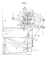
- FIG. 1 showing a vertical section through the central axis of a circular loom.
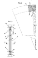
- Fig. 2 shows a detail of a section along the line II-II of Fig. 1 on an enlarged scale.
- FIG. 3 is a detail of a view in the direction of arrow III of FIG. 1.
- the circular loom has a drivable rotor 2 which is rotatably mounted in a machine frame 1 and which is arranged below a fixed circular-cylindrical reed 3.
- the reed 3 is delimited by a lower and an upper, ring-shaped race 4, 5, along which races at least one shooter 6 is guided by rollers 7. Between the races 4, 5 these connecting rods 8 of the reed 3 are provided, between which the warp threads 9, 10 are passed.
- the reed 3 concentrically surrounding thread guide members 12 are provided, which are formed by upper and lower guide rollers 13, 14 guided endless belts 15, to each of which a thread guide eye 16 is attached to each strand.
- the rotor 2 has a groove 17 (or spring) which runs in a wave-like manner over the circumference and on which driver elements 18 are guided.
- the driver elements 18 are connected to the belts 15 by means of actuating rods 19.
- thread tensioning devices 20 are provided for the warp threads 9, 10, which are formed by spring wires 21, which are each equipped with thread holders 22 at their free ends.
- the races 4, 5 have the guide surfaces 23 for the rollers 7 crossing thread guide grooves 24 for receiving the warp threads 9, 10 forming the compartment 11.
- the depth 25 of the thread guide grooves 24 is selected so that the warp threads 9, 10 do not lie against the bottom 26 of the thread guide grooves 24 when the compartment 11 is fully open (see FIG. 1), but come to lie at a short distance 27 therefrom.
- the webs 28 present between the thread guide grooves 24 have a width 29 which is twice as large as the width 30 of the thread guide groove 24.
- the guide surfaces 23 are thus only slightly interrupted by the thread guide grooves 24.
- the thread guide grooves 24 are aligned with the circumference of the Races 4, 5 arranged, formed by the reed 3 thread guides, the rods 8 of the reed 3 are each arranged in the extension of a web 28 outside the same.
- the thread guide grooves 24 are not arranged exactly radially to the central axis 31 of the machine, but they deviate from the radial direction in the running direction of the shooters 6 by an acute angle alpha, which ensures the smooth sliding or insertion of the Warp threads 9, 10, which are spread out by thread guides arranged on the shooter 6 and designed as thread guide brackets 32, are secured in the thread guide grooves 24.
- the insertion of the warp threads 9, 10 is further facilitated in that the thread guide grooves 24 have extensions 34 which are wedge-shaped at their ends directed towards the center 33 of the shed. These projections protrude beyond the guide surfaces 23 and at the same time form a support for the rollers 7 of the shooter 6.
- the acute angle alpha, with which the thread guide grooves 24 are arranged inclined with respect to the radial direction is preferably more than 1 °.
- a major advantage of the circular loom according to the invention can be seen in the fact that the warp threads 9, 10 - apart from the drive roller 35 driving the shooter 6 and rotatably mounted on the rotor 2 - only with the thread guide eyes 16 and with the thread guide bars 32 in the area of the compartment with machine parts come into contact so that you have a free hand in the construction of the guide surfaces 23 of the races 4, 5.
- the guide surfaces 23 are arranged inclined inwards and the upper guide surface 23 is provided with a support for the upper wheels 7 of the shooter 6, via which Guide surface 23 protruding inner edge 36 which prevents the shooter 6 from tipping inward when it is stationary.
- the races 4, 5 are advantageously made of plastic; they are assembled from initially straight-line sections, the individual sections having a foot 37, each of which is fitted into an annular groove 38 of the machine frame 1 and is fastened in this groove 38, for example by means of screws 39.
Landscapes
- Engineering & Computer Science (AREA)
- Textile Engineering (AREA)
- Looms (AREA)
- Auxiliary Weaving Apparatuses, Weavers' Tools, And Shuttles (AREA)
Abstract
Bei einer Rundwebmaschine mit einem Maschinengestell (1), einem im Maschengestell (1) angeordneten unteren und oberen Laufring (4, 5) zur Führung des Schützen (6) sind die Laufrollen (7) des Schützen (6) zwischen Führungsflächen (23) des oberen und unteren Laufringes eingepaßt Zur Vermeidung des Kontaktes der Laufrollen (7) des Schützen (6) mit den Kettfäden (9, 10) weisen die Laufringe (4, 5) die Führungsflächen (23) kreuzende Fadenführungsnuten auf, die gegenüber der radialen, an die Mittelachse (31) der Maschine gelegten Richtung in Laufrichtung der Schützen (6) um einen spitzen Winkel geneigt angeordnet sind.In a circular loom with a machine frame (1), a lower and upper race (4, 5) arranged in the mesh frame (1) for guiding the shooter (6), the rollers (7) of the shooter (6) are between guide surfaces (23) of the Upper and lower races fitted To avoid contact between the rollers (7) of the shooter (6) and the warp threads (9, 10), the races (4, 5) have thread guide grooves crossing the guide surfaces (23), which are opposite to the radial ones the central axis (31) of the machine in the running direction of the shooters (6) are arranged inclined at an acute angle.
Description
Die Erfindung betrifft eine Rundwebmaschine mit einem Maschinengestell, einem im Maschinengestell angeordneten unteren und oberen kreisförmigen Laufring zur Führung eines Schützen, dessen Laufrollen zwischen Führungsflächen des oberen und unteren Laufringes eingepaßt sind, wobei die Laufringe die Führungsflächen kreuzende Fadenführungsnuten aufweisen.The invention relates to a circular loom with a machine frame, a lower and upper circular race arranged in the machine frame for guiding a shooter, the rollers of which are fitted between guide surfaces of the upper and lower race, the races having thread guide grooves crossing the guide surfaces.
Eine Rundwebmaschine dieser Art ist aus der DE-B-1 535 586 bekannt. Hierbei sind die Laufrollen eines einen abgelängten Teiles des Schußfadens tragenden beweglichen Teiles zwischen kammartig ausgebildeten Führungsflächen eingepaßt. Die kammartig ausgebildeten Führungsflächen ermöglichen ein Eintauchen der Kettfäden in die Fadenführungsnuten dieser Führungsflächen, sodaß ein Kontakt der Laufrollen mit den Kettfäden vermieden werden kann. Die Fadenführungsnuten sind bei dieser bekannten Rundwebmaschine in radialer Richtung ausgerichtet. Dabei kann es, insbesondere bei schnellaufenden Rundwebmaschinen, deren Schützen mit Kettfadenleitbügeln zur vollständigen Öffnung des Faches versehen sind, dazu kommen, daß die Kettfäden nicht in die Fadenführungsnuten hineingleiten, sondern infolge des Kontakts mit dem umlaufenden Schützen von der radialen Richtung derart abgelenkt werden, daß sie auf den zwischen den Fadenführungsnuten erhabenen Stegen liegen bleiben und so von den Laufrädern des Schützen überrollt werden.A circular loom of this type is known from DE-B-1 535 586. In this case, the rollers of a movable part carrying a cut-off part of the weft thread are fitted between comb-shaped guide surfaces. The comb-like guide surfaces enable the warp threads to be immersed in the thread guide grooves of these guide surfaces, so that contact of the rollers with the warp threads can be avoided. The thread guide grooves are aligned in the radial direction in this known circular loom. It can, especially in high-speed circular looms, the shooters are provided with Kettfadenleitbügeln to fully open the compartment, that the warp threads do not slide into the thread guide grooves, but are deflected from the radial direction due to the contact with the rotating shooter so that they remain on the raised ridges between the thread guide grooves and are thus overrun by the shooter's wheels.
Es ist weiters bekannt (US-A - 1,720,151, DE-C - 805 026), zur Vermeidung eines Kontaktes der Kettfäden mit den Laufrollen bzw. einer Stützfläche des Schützen die Kettfäden in die Führungsflächen für die Laufrollen des Schützen kreuzende Fadenführungsnuten einzulegen, wobei auch hier die Fadenführungsnuten radial zur Mittelachse der Rundwebmaschine gerichtet sind. Diese bekannten Konstruktionen sind daher ebenfalls nicht für schnell laufende Maschinen geeignet, da die Kettfäden bei schnell laufenden Maschinen oftmals nicht in die Fadenführungsnuten hineingleiten, sondern auf den Stegen zwischen den Fadenführungsnuten liegen bleiben.It is further known (US-A-1,720,151, DE-C-805 026) to insert the warp threads into the guiding surfaces for the marksman's crossing guide grooves to avoid contact of the warp threads with the rollers or a support surface of the shooter, and also here the thread guide grooves radially to the central axis of the Circular loom are directed. These known constructions are therefore also not suitable for high-speed machines, since the warp threads in high-speed machines often do not slide into the thread guide grooves, but remain on the webs between the thread guide grooves.
Die Erfindung bezweckt die Vermeidung dieser Nachteile und Schwierigkeiten und stellt sich die Aufgabe, eine Rundwebmaschine der eingangs beschriebenen Art zu schaffen, die für höchste Webleistungen geeignet ist, wobei ein Schützen mit Kettfadenleitbügel - zur vollständigen Öffnung des Faches beim Eintritt des Schützen in das Fach - Verwendung finden kann.The invention aims to avoid these disadvantages and difficulties and has as its object to create a circular loom of the type described above, which is suitable for the highest weaving performance, with a shooter with warp thread guide bar - for completely opening the compartment when the shooter enters the compartment - Can be used.
Diese Aufgabe wird erfindungsgemäß dadurch gelöst, daß die Fadenführungsnuten gegenüber der radialen, an die Mittelachse der Maschine gelegten Richtung in Laufrichtung der Schützen um einen spitzen Winkel (alpha) geneigt angeordnet sind.This object is achieved in that the thread guide grooves are inclined at an acute angle (alpha) relative to the radial direction on the central axis of the machine in the running direction of the shooters.
Vorzugsweise sind die Fadenführungsnuten um einen mindestens 1° betragenden Winkel gegenüber der radialen Richtung geneigt angeordnet.The thread guide grooves are preferably arranged inclined at an angle of at least 1 ° with respect to the radial direction.
Ein besonders leichtes Einlegen bzw. Hineingleiten der Kettfäden in die Fadenführungsnuten ist vorzugsweise dadurch gesichert, daß die zwischen den Fadenführungsnuten liegenden Stege an ihren zur Fachmitte gerichteten Enden keilförmig zulaufende Fortsätze aufweisen.A particularly easy insertion or sliding of the warp threads into the thread guide grooves is preferably ensured in that the webs lying between the thread guide grooves have tapered extensions at their ends directed towards the center of the shed.
Um ein vibrationsfreies Abrollen der Laufräder des Schützen zu sichern, weisen zweckmäßig die zwischen den Fadenführungsnuten liegenden, die Führungsflächen tragenden Stege eine größere Breite auf als die Breite der Fadenführungsnuten, wobei vorteilhaft das Verhältnis der Breite eines Steges zur Breite einer Fadenführungsnut etwa zwei zu eins beträgt.In order to ensure vibration-free rolling of the shooter's running wheels, the webs lying between the thread guide grooves and carrying the guide surfaces expediently have a greater width than the width of the thread guide grooves, the ratio of advantageously Width of a web to the width of a thread guide groove is about two to one.
Infolge der Fadenführungsnuten ist es möglich, für die Laufringe auch komplizierte Querschnittsformen zu wählen. So sind z.B. für sehr große Laufgeschwindigkeiten des Schützen die Führungsflächen der Laufringe zweckmäßig nach innen geneigt ausgebildet.As a result of the thread guide grooves, it is also possible to choose complicated cross-sectional shapes for the races. For example, for very high running speeds of the shooter, the guide surfaces of the races are expediently inclined inwards.
Vorzugsweise sind die Laufringe aus Kunststoff, insbesondere Polyoxymethylen oder einem Polyamid, vorzugsweise nach der Spritzgußtechnik, nach der Spritzpreßtechnik oder durch Gießen, gefertigt, wodurch eine besonders einfache Herstellung der Laufringe möglich ist.The races are preferably made of plastic, in particular polyoxymethylene or a polyamide, preferably by the injection molding technique, by the injection molding technique or by casting, which makes the races particularly easy to manufacture.
Gemäß einer bevorzugten Ausführungsform sind die Laufringe aus zunächst geradlinig erzeugten Teilstücken zusammengesetzt, die in eine kreisringförmige Nut des Maschinengestells eingepaßt und in dieser Nut befestigt sind.According to a preferred embodiment, the races are composed of initially straight-line sections which are fitted into an annular groove in the machine frame and fastened in this groove.
Die Erfindung ist nachstehend anhand der Zeichnung an einem Ausführungsbeispiel näher erläutert, wobei Fig. 1 einen durch die Mittelachse einer Rundwebmaschine geführten Vertikalschnitt zeigt. Fig. 2 zeigt ein Detail eines Schnittes gemäß der Linie II-II der Fig. 1 im vergrößerten Maßstab. Fig. 3 ist ein Detail einer Ansicht in Richtung des Pfeiles III der Fig. 1.The invention is explained in more detail below with reference to the drawing using an exemplary embodiment, FIG. 1 showing a vertical section through the central axis of a circular loom. Fig. 2 shows a detail of a section along the line II-II of Fig. 1 on an enlarged scale. FIG. 3 is a detail of a view in the direction of arrow III of FIG. 1.
Die Rundwebmaschine weist einen in einem Maschinengestell 1 drehbar gelagerten antreibbaren Rotor 2 auf, der unterhalb eines ortsfesten kreiszylindrischen Rietes 3 angeordnet ist. Das Riet 3 wird von einem unteren und oberen, jeweils kreisringförmigen Laufring 4, 5 begrenzt, entlang welcher Laufringe mindestens ein Schützen 6 mittels Laufrollen 7 geführt ist. Zwischen den Laufringen 4, 5 sind diese verbindende Stäbe 8 des Rietes 3 vorgesehen, zwischen welchen die Kettfäden 9, 10 hindurchgeführt sind.The circular loom has a
Zur Bildung eines Faches 11 durch die Kettfäden 9, 10 sind das Riet 3 konzentrisch umgebend Fadenführungsorgane 12 vorgesehen, die von über obere und untere Umlenkrollen 13, 14 geführten endlosen Bändern 15 gebildet sind, an denen jeweils an jedem Trum eine Fadenführungsöse 16 befestigt ist. Zur Betätigung der Fadenführungsorgane 12 weist der Rotor 2 eine über den Umfang höhenmäßig wellenförmig verlaufende Nut 17 (oder Feder) auf, an der Mitnehmerelemente 18 geführt sind. Die Mitnehmerelemente 18 sind mittels Betätigungsstangen 19 mit den Bändern 15 verbunden. An der Außenseite des Maschinengestells 1 sind Fadenspanneinrichtungen 20 für die Kettfäden 9, 10 vorgesehen, die von Federdrähten 21, die an ihren freien Enden jeweils mit Fadenhalterungen 22 ausgestattet sind, gebildet sind.To form a
Die Laufringe 4, 5 weisen zur Aufnahme der das Fach 11 bildenden Kettfäden 9, 10 die Führungsflächen 23 für die Laufrollen 7 kreuzende Fadenführungsnuten 24 auf. Die Tiefe 25 der Fadenführungsnuten 24 ist so gewählt, daß die Kettfäden 9, 10 bei vollständig geöffnetem Fach 11 (vgl. Fig. 1) nicht am Boden 26 der Fadenführungsnuten 24 anliegen, sondern in geringem Abstand 27 von diesem zu liegen kommen. Die zwischen den Fadenführungsnuten 24 vorhandenen Stege 28 weisen etwa eine Breite 29 auf, die doppelt so groß ist wie die Breite 30 der Fadenführungsnut 24. Die Führungsflächen 23 sind somit durch die Fadenführungsnuten 24 nur geringfügig unterbrochen.The
Die Fadenführungsnuten 24 fluchten mit den am Umfang der Laufringe 4, 5 angeordneten, vom Riet 3 gebildeten Fadenführungen, wobei die Stäbe 8 des Rietes 3 jeweils in Verlängerung eines Steges 28 außerhalb desselben angeordnet sind.The
Wie aus Fig. 2 ersichtlich ist, sind die Fadenführungsnuten 24 nicht genau radial zur Mittelachse 31 der Maschine gerichtet angeordnet, sondern sie weichen von der radialen Richtung in Laufrichtung der Schützen 6 um einen spitzen Winkel alpha ab, wodurch das einwandfreie Hineingleiten bzw. Einlegen der Kettfäden 9, 10, die durch am Schützen 6 angeordnete Fadenführungen, die als Fadenleitbügel 32 ausgebildet sind, aufgespreizt sind, in die Fadenführungsnuten 24 gesichert ist. Das Einlegen der Kettfäden 9, 10 wird weiters dadurch erleichtert, daß die Fadenführungsnuten 24 an ihren zur Fachmitte 33 gerichteten Enden keilförmig gestaltete Fortsätze 34 aufweisen. Diese Fortsätze ragen über die Führungsflächen 23 hinaus und bilden gleichzeitig eine Abstützung für die Laufrollen 7 des Schützen 6. Der spitze Winkel alpha, mit dem die Fadenführungsnuten 24 gegenüber der radialen Richtung geneigt angeordnet sind, beträgt vorzugsweise mehr als 1°.As can be seen from Fig. 2, the
Ein wesentlicher Vorteil der erfindungsgemäßen Rundwebmaschine ist darin zu sehen, daß die Kettfäden 9, 10 - außer mit der den Schützen 6 antreibenden, am Rotor 2 drehbar gelagerten Antriebsrolle 35 - lediglich mit den Fadenführungsösen 16 und mit den Fadenleitbügeln 32 im Bereich des Faches mit Maschinenteilen in Berührung kommen, so daß man bei der Konstruktion der Führungsflächen 23 der Laufringe 4, 5 freie Hand hat. So sind z.B. gemäß dem dargestellten Ausführungsbeispiel die Führungsflächen 23 schräg nach innen geneigt angeordnet und ist die obere Führungsfläche 23 mit einem die oberen Laufräder 7 des Schützen 6 stützenden, über die Führungsfläche 23 emporragenden Innenrand 36 versehen, der ein Nach-Innen-Kippen des Schützen 6 bei dessen Stillstand verhindert. Die Laufringe 4, 5 sind zweckmäßig aus Kunststoff gefertigt; sie werden aus zunächst geradlinig erzeugten Teilstücken zusammengesetzt, wobei die einzelnen Teilstücke einen Fuß 37 aufweisen, der jeweils in eine kreisringförmige Nut 38 des Maschinengestells 1 eingepaßt ist und in dieser Nut 38 befestigt ist, beispielsweise mittels Schrauben 39.A major advantage of the circular loom according to the invention can be seen in the fact that the warp threads 9, 10 - apart from the
Claims (8)
Applications Claiming Priority (2)
| Application Number | Priority Date | Filing Date | Title |
|---|---|---|---|
| AT0190686A AT385784B (en) | 1986-07-14 | 1986-07-14 | ROUND WEAVING MACHINE |
| AT1906/86 | 1986-07-14 |
Publications (2)
| Publication Number | Publication Date |
|---|---|
| EP0253799A2 true EP0253799A2 (en) | 1988-01-20 |
| EP0253799A3 EP0253799A3 (en) | 1990-03-07 |
Family
ID=3523583
Family Applications (1)
| Application Number | Title | Priority Date | Filing Date |
|---|---|---|---|
| EP87890166A Withdrawn EP0253799A3 (en) | 1986-07-14 | 1987-07-09 | Circular weaving loom |
Country Status (6)
| Country | Link |
|---|---|
| US (1) | US4776371A (en) |
| EP (1) | EP0253799A3 (en) |
| JP (1) | JPS6328940A (en) |
| CN (1) | CN1004560B (en) |
| AT (1) | AT385784B (en) |
| ZA (1) | ZA874928B (en) |
Cited By (3)
| Publication number | Priority date | Publication date | Assignee | Title |
|---|---|---|---|---|
| EP3438335A1 (en) * | 2017-08-01 | 2019-02-06 | Reinhold Hehenberger | Reed and circular loom |
| WO2019025043A1 (en) | 2017-08-01 | 2019-02-07 | Reinhold Hehenberger | Circular weaving machine |
| AT524953B1 (en) * | 2021-12-22 | 2022-11-15 | Protoh Og | circular loom |
Families Citing this family (5)
| Publication number | Priority date | Publication date | Assignee | Title |
|---|---|---|---|---|
| JPH02293440A (en) * | 1989-05-02 | 1990-12-04 | Torii Tekkosho:Kk | Shuttle-supporting mechanism of circular loom |
| CN102747515B (en) * | 2012-07-13 | 2013-09-25 | 太平洋机电(集团)有限公司 | Weft insertion device of circular loom |
| EP2829645B1 (en) * | 2013-07-24 | 2018-09-05 | Starlinger & Co Gesellschaft m.b.H. | Circular looms |
| KR20190002679A (en) * | 2016-05-04 | 2019-01-08 | 이노텍 라이트웨이트 엔지니어링 & 폴리머 테크놀로지 게엠베하 | Method for making circular looms and hollow profile fabrics |
| US11352721B2 (en) * | 2019-07-24 | 2022-06-07 | Innotec Lightweight Engineering & Polymer Technology Gmbh | Circular loom with orbit path |
Citations (3)
| Publication number | Priority date | Publication date | Assignee | Title |
|---|---|---|---|---|
| GB493928A (en) * | 1936-01-11 | 1938-10-17 | Cfcmug | Improvements in or relating to synchronous motors |
| DE805026C (en) * | 1945-06-13 | 1951-05-04 | Comptoir Linier Sa | Electric circular loom |
| GB1160581A (en) * | 1965-09-17 | 1969-08-06 | Peltzer & Fils Sa | Circular Weaving Looms |
Family Cites Families (5)
| Publication number | Priority date | Publication date | Assignee | Title |
|---|---|---|---|---|
| FR615015A (en) * | 1926-04-24 | 1926-12-28 | Improvements in circular looms | |
| US2248282A (en) * | 1939-07-18 | 1941-07-08 | Saint Freres Sa Soc | Device for guiding the shuttles in circular weaving looms |
| FR1388875A (en) * | 1963-12-30 | 1965-02-12 | Device for driving and braking shuttles for circular looms | |
| CS266317B2 (en) * | 1982-07-02 | 1989-12-13 | Franz Xaver Huemer | Circular weaving machine |
| CH663227A5 (en) * | 1984-06-08 | 1987-11-30 | Huemer Franz Xaver | ROUND WEAVING MACHINE. |
-
1986
- 1986-07-14 AT AT0190686A patent/AT385784B/en not_active IP Right Cessation
-
1987
- 1987-07-07 ZA ZA874928A patent/ZA874928B/en unknown
- 1987-07-08 CN CN87104791.8A patent/CN1004560B/en not_active Expired
- 1987-07-09 US US07/071,291 patent/US4776371A/en not_active Expired - Fee Related
- 1987-07-09 EP EP87890166A patent/EP0253799A3/en not_active Withdrawn
- 1987-07-13 JP JP62174578A patent/JPS6328940A/en active Pending
Patent Citations (3)
| Publication number | Priority date | Publication date | Assignee | Title |
|---|---|---|---|---|
| GB493928A (en) * | 1936-01-11 | 1938-10-17 | Cfcmug | Improvements in or relating to synchronous motors |
| DE805026C (en) * | 1945-06-13 | 1951-05-04 | Comptoir Linier Sa | Electric circular loom |
| GB1160581A (en) * | 1965-09-17 | 1969-08-06 | Peltzer & Fils Sa | Circular Weaving Looms |
Cited By (5)
| Publication number | Priority date | Publication date | Assignee | Title |
|---|---|---|---|---|
| EP3438335A1 (en) * | 2017-08-01 | 2019-02-06 | Reinhold Hehenberger | Reed and circular loom |
| WO2019025043A1 (en) | 2017-08-01 | 2019-02-07 | Reinhold Hehenberger | Circular weaving machine |
| AT524953B1 (en) * | 2021-12-22 | 2022-11-15 | Protoh Og | circular loom |
| AT524953A4 (en) * | 2021-12-22 | 2022-11-15 | Protoh Og | circular loom |
| WO2023115091A1 (en) | 2021-12-22 | 2023-06-29 | Starlinger & Co Gesellschaft M.B.H. | Circular loom |
Also Published As
| Publication number | Publication date |
|---|---|
| ATA190686A (en) | 1987-10-15 |
| CN1004560B (en) | 1989-06-21 |
| AT385784B (en) | 1988-05-10 |
| JPS6328940A (en) | 1988-02-06 |
| CN87104791A (en) | 1988-01-27 |
| US4776371A (en) | 1988-10-11 |
| EP0253799A3 (en) | 1990-03-07 |
| ZA874928B (en) | 1988-03-30 |
Similar Documents
| Publication | Publication Date | Title |
|---|---|---|
| DE2519448B1 (en) | FABRIC INLAY FOR TRANSVERSIBLE CONVEYOR BELTS | |
| EP0253857A1 (en) | Injection-moulded cage for roller bearings | |
| DE2941565C2 (en) | Ball screw | |
| EP0080453A2 (en) | Circular loom | |
| EP0253799A2 (en) | Circular weaving loom | |
| DE2519364A1 (en) | DEVICE FOR LINEAR GUIDANCE | |
| EP0257500A2 (en) | Air directing device | |
| CH663648A5 (en) | ROLL REFLECTOR. | |
| EP0253798A2 (en) | Circular weaving loom | |
| DE2803377C2 (en) | Device for traversing a thread in winding machines | |
| EP0004593A1 (en) | Linear motion ball sleeve bearing | |
| DE2648696A1 (en) | TOY | |
| DE3336327A1 (en) | NEEDLE ROLLER FOR TEXTILE MACHINES | |
| EP0213462B1 (en) | Traversing thread guide | |
| DE69307813T2 (en) | Cross element for endless drive element | |
| DE19825316B4 (en) | Device on a card with wandering cover (revolving lid) made of clothed cover rods | |
| EP0174533B1 (en) | Device for forming a leno selvage | |
| EP0900952B1 (en) | Belt drive | |
| DE3222600A1 (en) | NEEDLE STICKER | |
| DE4006733C2 (en) | Cable pull system, in particular cable pull linear wiper system for motor vehicles | |
| EP0929706B1 (en) | Method and device for twisting at least two running threads about one another | |
| DE2242755B2 (en) | Balloon limiter ring | |
| DE2253729B2 (en) | BREAD HOLDER CYLINDER | |
| DD250963B1 (en) | PNEUMATIC CLEANING DEVICE FOR TEXTILE MACHINES, INS. FOR WAVELESS WEAVING MACHINES | |
| EP0228542A1 (en) | Belt drive device, for instance for yarn feeding devices for textile machines |
Legal Events
| Date | Code | Title | Description |
|---|---|---|---|
| PUAI | Public reference made under article 153(3) epc to a published international application that has entered the european phase |
Free format text: ORIGINAL CODE: 0009012 |
|
| AK | Designated contracting states |
Kind code of ref document: A2 Designated state(s): DE GB IT |
|
| PUAL | Search report despatched |
Free format text: ORIGINAL CODE: 0009013 |
|
| AK | Designated contracting states |
Kind code of ref document: A3 Designated state(s): DE GB IT |
|
| STAA | Information on the status of an ep patent application or granted ep patent |
Free format text: STATUS: THE APPLICATION IS DEEMED TO BE WITHDRAWN |
|
| 18D | Application deemed to be withdrawn |
Effective date: 19900908 |
|
| RIN1 | Information on inventor provided before grant (corrected) |
Inventor name: NUSSDORFER, FRANZ, DIPL.-ING. Inventor name: SCHOENBERGER, JOHANN Inventor name: ROMAUER, EWALD Inventor name: KIENESBERGER, KARL Inventor name: ZACEK, FRANZ, DIPL.-ING. Inventor name: PICHLER, HERMANN Inventor name: WOLF, RUDOLF Inventor name: FOEDINGER, FRANZ |