EP0253771A2 - Fermoir pour parure - Google Patents
Fermoir pour parure Download PDFInfo
- Publication number
- EP0253771A2 EP0253771A2 EP87810390A EP87810390A EP0253771A2 EP 0253771 A2 EP0253771 A2 EP 0253771A2 EP 87810390 A EP87810390 A EP 87810390A EP 87810390 A EP87810390 A EP 87810390A EP 0253771 A2 EP0253771 A2 EP 0253771A2
- Authority
- EP
- European Patent Office
- Prior art keywords
- main element
- notch
- spring
- closure part
- closing
- Prior art date
- Legal status (The legal status is an assumption and is not a legal conclusion. Google has not performed a legal analysis and makes no representation as to the accuracy of the status listed.)
- Granted
Links
- 238000010276 construction Methods 0.000 description 3
- 239000002184 metal Substances 0.000 description 1
- 230000000717 retained effect Effects 0.000 description 1
Images
Classifications
-
- F—MECHANICAL ENGINEERING; LIGHTING; HEATING; WEAPONS; BLASTING
- F16—ENGINEERING ELEMENTS AND UNITS; GENERAL MEASURES FOR PRODUCING AND MAINTAINING EFFECTIVE FUNCTIONING OF MACHINES OR INSTALLATIONS; THERMAL INSULATION IN GENERAL
- F16B—DEVICES FOR FASTENING OR SECURING CONSTRUCTIONAL ELEMENTS OR MACHINE PARTS TOGETHER, e.g. NAILS, BOLTS, CIRCLIPS, CLAMPS, CLIPS OR WEDGES; JOINTS OR JOINTING
- F16B45/00—Hooks; Eyes
- F16B45/02—Hooks with pivoting or elastically bending closing member
- F16B45/027—Hooks with pivoting or elastically bending closing member and having position-locking means for the closing member
-
- F—MECHANICAL ENGINEERING; LIGHTING; HEATING; WEAPONS; BLASTING
- F16—ENGINEERING ELEMENTS AND UNITS; GENERAL MEASURES FOR PRODUCING AND MAINTAINING EFFECTIVE FUNCTIONING OF MACHINES OR INSTALLATIONS; THERMAL INSULATION IN GENERAL
- F16B—DEVICES FOR FASTENING OR SECURING CONSTRUCTIONAL ELEMENTS OR MACHINE PARTS TOGETHER, e.g. NAILS, BOLTS, CIRCLIPS, CLAMPS, CLIPS OR WEDGES; JOINTS OR JOINTING
- F16B45/00—Hooks; Eyes
- F16B45/02—Hooks with pivoting or elastically bending closing member
-
- A—HUMAN NECESSITIES
- A44—HABERDASHERY; JEWELLERY
- A44C—PERSONAL ADORNMENTS, e.g. JEWELLERY; COINS
- A44C5/00—Bracelets; Wrist-watch straps; Fastenings for bracelets or wrist-watch straps
- A44C5/18—Fasteners for straps, chains or the like
- A44C5/20—Fasteners for straps, chains or the like for open straps, chains or the like
- A44C5/2019—Hooks
- A44C5/2033—Hooks provided with pivoting closure means
- A44C5/2038—Swivels
-
- F—MECHANICAL ENGINEERING; LIGHTING; HEATING; WEAPONS; BLASTING
- F16—ENGINEERING ELEMENTS AND UNITS; GENERAL MEASURES FOR PRODUCING AND MAINTAINING EFFECTIVE FUNCTIONING OF MACHINES OR INSTALLATIONS; THERMAL INSULATION IN GENERAL
- F16B—DEVICES FOR FASTENING OR SECURING CONSTRUCTIONAL ELEMENTS OR MACHINE PARTS TOGETHER, e.g. NAILS, BOLTS, CIRCLIPS, CLAMPS, CLIPS OR WEDGES; JOINTS OR JOINTING
- F16B45/00—Hooks; Eyes
- F16B45/02—Hooks with pivoting or elastically bending closing member
- F16B45/023—Hooks with pivoting or elastically bending closing member the closing member pivoting about an axis perpendicular to the plane of the hook
-
- F—MECHANICAL ENGINEERING; LIGHTING; HEATING; WEAPONS; BLASTING
- F16—ENGINEERING ELEMENTS AND UNITS; GENERAL MEASURES FOR PRODUCING AND MAINTAINING EFFECTIVE FUNCTIONING OF MACHINES OR INSTALLATIONS; THERMAL INSULATION IN GENERAL
- F16B—DEVICES FOR FASTENING OR SECURING CONSTRUCTIONAL ELEMENTS OR MACHINE PARTS TOGETHER, e.g. NAILS, BOLTS, CIRCLIPS, CLAMPS, CLIPS OR WEDGES; JOINTS OR JOINTING
- F16B45/00—Hooks; Eyes
- F16B45/02—Hooks with pivoting or elastically bending closing member
- F16B45/024—Hooks with pivoting or elastically bending closing member and having means biasing the closing member about the pivot
-
- Y—GENERAL TAGGING OF NEW TECHNOLOGICAL DEVELOPMENTS; GENERAL TAGGING OF CROSS-SECTIONAL TECHNOLOGIES SPANNING OVER SEVERAL SECTIONS OF THE IPC; TECHNICAL SUBJECTS COVERED BY FORMER USPC CROSS-REFERENCE ART COLLECTIONS [XRACs] AND DIGESTS
- Y10—TECHNICAL SUBJECTS COVERED BY FORMER USPC
- Y10T—TECHNICAL SUBJECTS COVERED BY FORMER US CLASSIFICATION
- Y10T24/00—Buckles, buttons, clasps, etc.
- Y10T24/45—Separable-fastener or required component thereof [e.g., projection and cavity to complete interlock]
- Y10T24/45225—Separable-fastener or required component thereof [e.g., projection and cavity to complete interlock] including member having distinct formations and mating member selectively interlocking therewith
- Y10T24/45272—Projection passes through cavity then moves toward noninserted portion of its member to complete interlock [e.g., snap hook]
- Y10T24/45288—Hook type projection member
- Y10T24/45304—Noninserted portion of projection member includes movably connected gate for closing access throat
- Y10T24/45319—Pivotally connected gate
- Y10T24/45335—Pivotally connected gate having means biasing gate about pivot
Definitions
- the present invention relates to a clasp for adornment, and more particularly to a clasp for necklaces.
- the object of the invention is to provide a clasp which facilitates opening and closing, and which therefore makes it possible to easily put on and take off the adornment.
- clasps for adornment and in particular for necklaces or bracelets, which include a main element bent in a hook and a closure piece moved by a spring so as to close the opening presented by the main element in the form of a hook.
- the opening of the closure piece is controlled by the wearer's nail, and the hook is introduced into a ring attached to the other end of the set; once the hook in the ring, it is enough to release the pressure of the nail on the closing part so that it closes under the action of a spring and thus prevents the hook from get out of the ring.
- a bracelet for watches has also recently been proposed, which is locked to a ring adjoining the box by means of a clasp of the same type, which makes it possible to put on and take off the watch.
- This is a novelty in the drawing if we compare it to conventional products in which the opening and closing of the strap is done thanks to a metal part located in an intermediate portion of the watch strap.
- the closing piece of such conventional clasps, and especially for necklaces is so small that it is difficult for a woman with long nails to open the closing piece by pressing it with the tip of a nail .
- the difficulty is increased by the fact that the wearer of the collar must act without seeing what she is doing, the clasp being behind her neck.
- the closing piece In the case of the watch strap, the closing piece must be opened with one hand. As a rule, women therefore find it difficult to take off and put on ornaments, unless they are particularly skilled.
- German patent 1,261,402 describes a carabiner which has a curved main element and a closure piece which, in the open position, is retained by a hook; this hook is secured to a pivoting external lever and held in position by a spring.
- a spring To release the closing part, which itself tends to close under the action of a spring, it suffices to press the lever, which is located outside the device, thereby lifting the hook which releases the part closing; under the action of the spring, this part closes.
- This device has the advantage of keeping the closure part open without the need to exert constant pressure.
- the present invention aims to provide a clasp usable for ornaments, of simple construction and which may be small, and which allows the user to keep the closure part open without exerting constant pressure thereon.
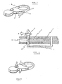
- the clasp has a main element 1 curved in the shape of a hook.
- a closing part 2 is fixed to this main element so as to be able to pivot.
- the closing piece has a tip shaped so as to close the opening of the hook formed by the main element, when the closing piece is in the closed position.
- the closure element has a another end 3, which protrudes from the main element and thus allows the closure part to be pivoted with the finger. In the embodiment shown here, the closure part pivots in the plane of the main element.
- the closing part is subjected to the action of a spring, which is not shown here, and which tends to keep it in the closed position.
- the closing part has a notch 4, which can also be a protuberance.
- a locking member 5 which here has the shape of a rod, preferably metallic, elastic, is fixed to the main element.
- This locking member appears entirely only in FIG. 2. It consists of a doubly bent rod. A first part of this rod is pressed perpendicularly into the main element. This first portion is followed by an elongated portion 7 substantially parallel to the plane of the main element, and which acts as a spring. This elongated portion is itself followed by a portion substantially perpendicular 8 to the plane of the main element and which passes through the latter. On the other side of the main element, that is to say on the side opposite to that where the elongated portion is located, the perpendicular portion ends with a button 6.
- the opening in the main element for the passage of the perpendicular portion is wide enough to allow a movement of the perpendicular portion when pressure is exerted on the button.
- the perpendicular portion is in contact with the closure part.
- the perpendicular portion of the locking member In the open position, the perpendicular portion of the locking member is introduced into the notch 4 and thus prevents the closure part from closing.
- To release the closing part it suffices to exert a pressure on the button 6, in the direction indicated by the vertical arrow in FIG. 2.
- the perpendicular portion of the locking member then deviates in the direction of the arrow B of Figure 2 and emerges from the notch, taking the position indicated by dotted lines.
- the closing part released, pivots in the direction of arrow C in FIG. 3 and closes the opening of the main element.
- To open the clasp simply operate the end 3 in the direction of arrow A in Figure 1.
- the perpendicular portion of the locking member first pushed by the edge of the notch, will be house
- the locking member 5 includes a spiral spring which assumes the function of spring provided in the embodiment represented here by the elongated portion 7.
- the embodiment shown in the drawings and described here shows a closure part provided with a notch in which is housed the perpendicular portion 8 of the locking member. None prevents, however, from replacing the notch by a protuberance which cooperates with the perpendicular portion. This is simply an inversion of functions, the result of which remains the same.
- the clasp according to the invention has a simple and elegant structure. It is easy to maneuver, even with one hand, and even behind the neck.
- An additional advantage of the clasp lies in the fact that, when the closing part 2 is released by the pressure exerted on the button 6, it closes under the action of the spring with a click which confirms the operation of the device at the person who sets the adornment without seeing the clasp.
Landscapes
- Engineering & Computer Science (AREA)
- General Engineering & Computer Science (AREA)
- Mechanical Engineering (AREA)
- Adornments (AREA)
- Hooks, Suction Cups, And Attachment By Adhesive Means (AREA)
- Supports Or Holders For Household Use (AREA)
- Cosmetics (AREA)
Abstract
Description
- La présente invention a trait à un fermoir pour parure, et plus particulièrement à un fermoir destiné à des colliers. Le but de l'invention est de fournir un fermoir qui facilite l'ouverture et la fermeture, et qui permette par conséquent de mettre et d'enlever facilement la parure.
- Il existe des fermoirs pour parure, et notamment pour des colliers ou des bracelets, qui comprennent un élément principal recourbé en crochet et une pièce de fermeture mue par un ressort de manière à fermer l'ouverture présentée par l'élément principal en forme de crochet. Dans la forme d'exécution la plus commune de ce genre de fermoirs, l'ouverture de la pièce de fermeture est commandée par l'ongle du porteur, et le crochet est introduit dans un anneau attachée à l'autre bout de la parure; une fois le crochet dans l'anneau, il suffit de relâcher la pression de l'ongle sur la pièce de fermeture pour que celle-ci se referme sous l'action d'un ressort et empêche ainsi le crochet de sortir de l'anneau.
- On a également proposé récemment un bracelet destiné aux montres, qui est verrouillé à un anneau attenant à la boîte au moyen d'un fermoir du même type, qui permet de mettre et d'enlever la montre. Il s'agit là d'une nouveauté dans le dessin si on la compare aux produits classiques dans lesquels l'ouverture et la fermeture du bracelet se font grâce à une partie métallique située dans une portion intermédiaire du bracelet de montre.
- Habituellement, la pièce de fermeture de tels fermoirs classiques, et spécialement pour des colliers, est tellement petite qu'il est difficile à une femme qui a de longs ongles d'ouvrir la pièce de fermeture en la pressant avec le bout d'un ongle. De plus, dans le cas d'un collier, la difficulté est accrue du fait que la porteuse du collier doit agir sans voir ce qu'elle fait, le fermoir se trouvant derrière son cou. Dans le cas du bracelet de montre, la pièce de fermeture doit être ouverte d'une seule main. En règle générale, les femmes considèrent donc qu'il est difficile d'enlever et de mettre des parures, sauf si elles sont particulièrement habiles.
- On a certes proposé, dans un domaine extérieur à celui des parures, des fermoirs qui peuvent être maniés d'une seule main et qui présentent certains avantages par rapport aux fermoirs classiques. Par exemple, le brevet allemand 1'261'402 décrit un mousqueton qui présente un élément principal recourbé et une pièce de fermeture qui, en position ouverte, est retenue par un crochet; ce crochet est solidaire d'un levier extérieur pivotant et maintenu en position par un ressort. Pour libérer la pièce de fermeture, qui tend elle-même à se refermer sous l'action d'un ressort, il suffit de presser le levier, qui se trouve à l'extérieur du dispositif, en soulevant ainsi le crochet qui libère la pièce de fermeture; sous l'action du ressort, cette pièce se referme. Ce dispositif présente l'avantage de conserver ouverte la pièce de fermeture sans qu'il soit besoin d'exercer une pression constante.
- Cependant, un tel dispositif présente une construction peu élégante et n'est guère utilisable pour une parure. De plus, sa construction dans des dimensions réduites est assez difficile.
- La présente invention vise à fournir un fermoir utilisable pour des parures, d'une construction simple et qui puisse être de faibles dimensions, et qui permette à l'utilisateur de conserver ouverte la pièce de fermeture sans exercer une pression constante sur celle-ci.
- L'invention est décrite dans les revendications.
- Les dessins représentent, à titre d'exemple, une forme d'exécution de l'invention.
- La figure 1 est une vue en perspective cavalière montrant le fermoir en position fermée.
- La figure 2 est une coupe partielle d'un fermoir selon l'invention.
- La figure 3 est une vue en perspective du fermoir en position ouverte.
- Le fermoir présente un élément principal 1 recourbé en forme de crochet. Une pièce de fermeture 2 est fixée à cet élément principal de manière à pouvoir pivoter. La pièce de fermeture présente un bout conformé de manière à fermer l'ouverture du crochet formé par l'élément principal, lorsque la pièce de fermeture est en position fermée. L'élément de fermeture présente un autre bout 3, qui dépasse de l'élément principal et permet ainsi de faire pivoter la pièce de fermeture avec le doigt. Dans la forme d'exécution représentée ici, la pièce de fermeture pivote dans le plan de l'élément principal. La piéce de fermeture est soumise à l'action d'un ressort, qui n'est pas représenté ici, et qui tend à la maintenir en position fermée. La pièce de fermeture présente un cran 4, qui peut aussi être une protubérance. Un membre de verrouillage 5, qui présente ici la forme d'une tige, de préférence métallique, élastique, est fixé à l'élément principal. Ce membre de verrouillage n'apparaît entièrement que dans le figure 2. Il consiste en une tige doublement coudée. Une première partie de cette tige est enfoncée perpendiculairement dans l'élément principal. Cette première portion est suivie d'une portion allongée 7 sensiblement parallèle au plan de l'élément principal, et qui fait office de ressort. Cette portion allongée est elle-même suivie d'une portion sensiblement perpendiculaire 8 au plan de l'élément principal et qui traverse ce dernier. De l'autre côté de l'élément principal, c'est-à-dire du côté opposé à celui où se trouve la portion allongée, la portion perpendiculaire se termine par un bouton 6. L'ouverture ménagée dans l'élément principal pour le passage de la portion perpendiculaire est suffisamment large pour permettre un débattement de la portion perpendiculaire lorsqu'une pression est exercée sur le bouton. La portion perpendiculaire est en contact avec la pièce de fermeture. En position ouverte, la portion perpendiculaire du membre de verrouillage est introduite dans le cran 4 et empêche ainsi la pièce de fermeture de se refermer. Pour dégager la piéce de fermeture, il suffit ainsi d'exercer une pression sur le bouton 6, dans le sens indiqué par la flèche verticale de la figure 2. La portion perpendiculaire du membre de verrouillage s'écarte alors dans le sens de la flèche B de la figure 2 et se dégage du cran, en prenant la position indiquée par des pointillés. La pièce de fermeture, libérée, pivote dans le sens de la flèche C de la figure 3 et referme l'ouverture de l'élément principal. Pour ouvrir le fermoir, il suffit de manoeuvrer le bout 3 dans le sens de la flèche A de la figure 1. La portion perpendiculaire du membre de verrouillage, d'abord repoussée par le bord du cran, viendra se loger dans ce dernier au moment où il se trouvera en face d'elle.
- Dans une autre forme d'exécution, qui n'est pas représentée ici, le membre de verrouillage 5 inclut un ressort spiral qui assume la fonction de ressort assuré dans la forme d'exécution représentée ici par la portion allongée 7.
- D'autre part, la forme d'exécution représentée dans les dessins et décrite ici montre une pièce de fermeture pourvue d'un cran dans lequel vient se loger la portion perpendiculaire 8 du membre de verrouillage. Rien n'empêche cependant de remplacer le cran par une protubérance qui coopère avec la portion perpendiculaire. Il s'agit là simplement d'une interversion des fonctions dont le résultat reste le même.
- Le fermoir selon l'invention a une structure simple et élégante. Il est aisé à manoeuvré, même d'une seule main, et même derrière le cou. Un avantage supplémentaire du fermoir réside dans le fait que, au moment où la pièce de fermeture 2 est relâchée par la pression exercée sur le bouton 6, elle se ferme sous l'action du ressort avec un déclic qui confirme le fonctionnement du dispositif à la personne qui met la parure sans voir le fermoir.
Claims (4)
Priority Applications (1)
| Application Number | Priority Date | Filing Date | Title |
|---|---|---|---|
| AT87810390T ATE62111T1 (de) | 1986-07-18 | 1987-07-09 | Schmuckverschluss. |
Applications Claiming Priority (2)
| Application Number | Priority Date | Filing Date | Title |
|---|---|---|---|
| JP61167829A JPH0720443B2 (ja) | 1986-07-18 | 1986-07-18 | 装身具用留め金 |
| JP167829/86 | 1986-07-18 |
Publications (3)
| Publication Number | Publication Date |
|---|---|
| EP0253771A2 true EP0253771A2 (fr) | 1988-01-20 |
| EP0253771A3 EP0253771A3 (en) | 1989-01-04 |
| EP0253771B1 EP0253771B1 (fr) | 1991-04-03 |
Family
ID=15856865
Family Applications (1)
| Application Number | Title | Priority Date | Filing Date |
|---|---|---|---|
| EP87810390A Expired - Lifetime EP0253771B1 (fr) | 1986-07-18 | 1987-07-09 | Fermoir pour parure |
Country Status (6)
| Country | Link |
|---|---|
| US (1) | US4712279A (fr) |
| EP (1) | EP0253771B1 (fr) |
| JP (1) | JPH0720443B2 (fr) |
| AT (1) | ATE62111T1 (fr) |
| DE (1) | DE3769022D1 (fr) |
| ES (1) | ES2021750B3 (fr) |
Families Citing this family (4)
| Publication number | Priority date | Publication date | Assignee | Title |
|---|---|---|---|---|
| IT8801226A0 (it) * | 1988-06-30 | 1988-06-30 | Spinelli Andrea | Struttura contenitrice della chiusura "a pappagallo" e metodo di realizzazione |
| US7126484B1 (en) | 2002-05-03 | 2006-10-24 | Luquire L Hanson | Snap-hook assemblies with added components |
| US7343760B2 (en) * | 2004-07-30 | 2008-03-18 | Melissa Tyler | Body jewelry |
| FR3082707A1 (fr) * | 2018-06-21 | 2019-12-27 | Louis Pueyo | Fermoir pour bracelets de bijouterie et d'horlogerie |
Citations (7)
| Publication number | Priority date | Publication date | Assignee | Title |
|---|---|---|---|---|
| DE60359C (de) * | P. M. WEIMAR und W. WEIMAR in Kiel, Ringstr. 72 | Sicherheitshaken mit an der Aufhängeöse festem Schliefstheil | ||
| FR593136A (fr) * | 1925-02-10 | 1925-08-17 | Fermoir à ressort | |
| US1576352A (en) * | 1925-03-21 | 1926-03-09 | Nordling Peter August | Hook |
| FR1160603A (fr) * | 1956-11-22 | 1958-07-22 | Porte-clés | |
| DE1261402B (de) * | 1957-12-21 | 1968-02-15 | Ing Sepp Steinbichler | Karabinerhaken |
| GB2106584A (en) * | 1981-09-29 | 1983-04-13 | Britax Excelsior | Fasteners |
| DE8515574U1 (de) * | 1985-05-25 | 1985-07-11 | Pfitzenmeier, Wulf, 7530 Pforzheim | Verschlußelement, insbesondere für Schmuckketten |
Family Cites Families (8)
| Publication number | Priority date | Publication date | Assignee | Title |
|---|---|---|---|---|
| US544483A (en) * | 1895-08-13 | Wesley eckert | ||
| US158220A (en) * | 1874-12-29 | Improvement in snap-hooks | ||
| US90938A (en) * | 1869-06-08 | Improved tug-hook | ||
| US628619A (en) * | 1897-08-17 | 1899-07-11 | Josiah K Alwood | Harness-snap. |
| US739226A (en) * | 1903-05-28 | 1903-09-15 | Osmer W Sanborn | Safety snap-hook. |
| US1166952A (en) * | 1915-04-14 | 1916-01-04 | Oscar W Wahlstrom | Chain-link. |
| US2216499A (en) * | 1940-05-08 | 1940-10-01 | John H Ohotto | Snap fastener |
| US3950828A (en) * | 1975-02-03 | 1976-04-20 | American Gold Chain Company, Inc. | Chain clasp |
-
1986
- 1986-07-18 JP JP61167829A patent/JPH0720443B2/ja not_active Expired - Lifetime
- 1986-09-16 US US06/907,913 patent/US4712279A/en not_active Expired - Fee Related
-
1987
- 1987-07-09 AT AT87810390T patent/ATE62111T1/de not_active IP Right Cessation
- 1987-07-09 ES ES87810390T patent/ES2021750B3/es not_active Expired - Lifetime
- 1987-07-09 DE DE8787810390T patent/DE3769022D1/de not_active Expired - Fee Related
- 1987-07-09 EP EP87810390A patent/EP0253771B1/fr not_active Expired - Lifetime
Patent Citations (7)
| Publication number | Priority date | Publication date | Assignee | Title |
|---|---|---|---|---|
| DE60359C (de) * | P. M. WEIMAR und W. WEIMAR in Kiel, Ringstr. 72 | Sicherheitshaken mit an der Aufhängeöse festem Schliefstheil | ||
| FR593136A (fr) * | 1925-02-10 | 1925-08-17 | Fermoir à ressort | |
| US1576352A (en) * | 1925-03-21 | 1926-03-09 | Nordling Peter August | Hook |
| FR1160603A (fr) * | 1956-11-22 | 1958-07-22 | Porte-clés | |
| DE1261402B (de) * | 1957-12-21 | 1968-02-15 | Ing Sepp Steinbichler | Karabinerhaken |
| GB2106584A (en) * | 1981-09-29 | 1983-04-13 | Britax Excelsior | Fasteners |
| DE8515574U1 (de) * | 1985-05-25 | 1985-07-11 | Pfitzenmeier, Wulf, 7530 Pforzheim | Verschlußelement, insbesondere für Schmuckketten |
Also Published As
| Publication number | Publication date |
|---|---|
| ES2021750B3 (es) | 1991-11-16 |
| EP0253771B1 (fr) | 1991-04-03 |
| JPH0720443B2 (ja) | 1995-03-08 |
| DE3769022D1 (de) | 1991-05-08 |
| US4712279A (en) | 1987-12-15 |
| JPS6324905A (ja) | 1988-02-02 |
| EP0253771A3 (en) | 1989-01-04 |
| ATE62111T1 (de) | 1991-04-15 |
Similar Documents
| Publication | Publication Date | Title |
|---|---|---|
| US5117539A (en) | Clasp mechanism | |
| EP0253771B1 (fr) | Fermoir pour parure | |
| US5379611A (en) | Jewelry converter apparatus | |
| US6438809B1 (en) | Parrot clasp with an opening button | |
| EP0427634B1 (fr) | Fermeture de lien souple tel qu'un bracelet ou une ceinture | |
| US3319308A (en) | Jewelry clasp | |
| CH96026A (fr) | Fermoir automatique de sûreté pour bracelets, colliers, ceintures, etc. | |
| FR2495449A1 (fr) | Bijou transformable | |
| US6588075B2 (en) | Fish-hook clasp with a double activation mechanism | |
| US3001258A (en) | Jewelry clasp | |
| FR2500729A1 (fr) | Dispositif formant porte-objet, tel qu'un porte-cles, adaptable sur une ceinture | |
| FR2602648A1 (fr) | Dispositif de fixation pour article de bijouterie, horlogerie et maroquinerie et, notamment, d'une montre | |
| CH676073B5 (fr) | ||
| EP1269879B1 (fr) | Dispositif de fixation des brins de bracelet à une boîte | |
| US20050268651A1 (en) | Hands-free jewelry | |
| FR2955467A1 (fr) | Systeme de fermeture destine notamment a un bracelet, un collier ou une chaine | |
| EP0158152B1 (fr) | Fermoir à double sécurité pour bracelet | |
| EP0046123A1 (fr) | Fermoir pour chaînes, colliers ou bracelets | |
| EP1048991A1 (fr) | Dispositif d'interchangeabilité d'un bracelet de montre | |
| US20120279026A1 (en) | Ornament lock with wide opening ornament clasp | |
| CH675054A5 (fr) | ||
| EP1183958B1 (fr) | Fermoir de bracelet de montre | |
| WO2020225654A1 (fr) | Fermoir à boucle déployante | |
| US2596405A (en) | Jewelry clasp | |
| CH283851A (fr) | Fermoir pour article de bijouterie, notamment pour collier. |
Legal Events
| Date | Code | Title | Description |
|---|---|---|---|
| PUAI | Public reference made under article 153(3) epc to a published international application that has entered the european phase |
Free format text: ORIGINAL CODE: 0009012 |
|
| 17P | Request for examination filed |
Effective date: 19870717 |
|
| AK | Designated contracting states |
Kind code of ref document: A2 Designated state(s): AT BE CH DE ES FR GB IT LI |
|
| PUAL | Search report despatched |
Free format text: ORIGINAL CODE: 0009013 |
|
| AK | Designated contracting states |
Kind code of ref document: A3 Designated state(s): AT BE CH DE ES FR GB IT LI |
|
| 17Q | First examination report despatched |
Effective date: 19900629 |
|
| ITF | It: translation for a ep patent filed |
Owner name: STUDIO MASSARI S.R.L. |
|
| GRAA | (expected) grant |
Free format text: ORIGINAL CODE: 0009210 |
|
| AK | Designated contracting states |
Kind code of ref document: B1 Designated state(s): AT BE CH DE ES FR GB IT LI |
|
| REF | Corresponds to: |
Ref document number: 62111 Country of ref document: AT Date of ref document: 19910415 Kind code of ref document: T |
|
| GBT | Gb: translation of ep patent filed (gb section 77(6)(a)/1977) | ||
| REF | Corresponds to: |
Ref document number: 3769022 Country of ref document: DE Date of ref document: 19910508 |
|
| PLBE | No opposition filed within time limit |
Free format text: ORIGINAL CODE: 0009261 |
|
| STAA | Information on the status of an ep patent application or granted ep patent |
Free format text: STATUS: NO OPPOSITION FILED WITHIN TIME LIMIT |
|
| 26N | No opposition filed | ||
| PGFP | Annual fee paid to national office [announced via postgrant information from national office to epo] |
Ref country code: GB Payment date: 19930607 Year of fee payment: 7 |
|
| PGFP | Annual fee paid to national office [announced via postgrant information from national office to epo] |
Ref country code: CH Payment date: 19930618 Year of fee payment: 7 |
|
| PGFP | Annual fee paid to national office [announced via postgrant information from national office to epo] |
Ref country code: BE Payment date: 19930621 Year of fee payment: 7 |
|
| PGFP | Annual fee paid to national office [announced via postgrant information from national office to epo] |
Ref country code: ES Payment date: 19930623 Year of fee payment: 7 |
|
| PGFP | Annual fee paid to national office [announced via postgrant information from national office to epo] |
Ref country code: FR Payment date: 19930708 Year of fee payment: 7 |
|
| PGFP | Annual fee paid to national office [announced via postgrant information from national office to epo] |
Ref country code: AT Payment date: 19930715 Year of fee payment: 7 |
|
| PGFP | Annual fee paid to national office [announced via postgrant information from national office to epo] |
Ref country code: DE Payment date: 19930819 Year of fee payment: 7 |
|
| PG25 | Lapsed in a contracting state [announced via postgrant information from national office to epo] |
Ref country code: GB Effective date: 19940709 Ref country code: AT Effective date: 19940709 |
|
| PG25 | Lapsed in a contracting state [announced via postgrant information from national office to epo] |
Ref country code: ES Free format text: LAPSE BECAUSE OF EXPIRATION OF PROTECTION Effective date: 19940711 |
|
| PG25 | Lapsed in a contracting state [announced via postgrant information from national office to epo] |
Ref country code: LI Effective date: 19940731 Ref country code: CH Effective date: 19940731 Ref country code: BE Effective date: 19940731 |
|
| BERE | Be: lapsed |
Owner name: HEIWADO BOUEKI K.K. Effective date: 19940731 |
|
| GBPC | Gb: european patent ceased through non-payment of renewal fee |
Effective date: 19940709 |
|
| PG25 | Lapsed in a contracting state [announced via postgrant information from national office to epo] |
Ref country code: FR Effective date: 19950331 |
|
| REG | Reference to a national code |
Ref country code: CH Ref legal event code: PL |
|
| PG25 | Lapsed in a contracting state [announced via postgrant information from national office to epo] |
Ref country code: DE Effective date: 19950401 |
|
| REG | Reference to a national code |
Ref country code: FR Ref legal event code: ST |
|
| REG | Reference to a national code |
Ref country code: ES Ref legal event code: FD2A Effective date: 19990601 |
|
| PG25 | Lapsed in a contracting state [announced via postgrant information from national office to epo] |
Ref country code: IT Free format text: LAPSE BECAUSE OF NON-PAYMENT OF DUE FEES;WARNING: LAPSES OF ITALIAN PATENTS WITH EFFECTIVE DATE BEFORE 2007 MAY HAVE OCCURRED AT ANY TIME BEFORE 2007. THE CORRECT EFFECTIVE DATE MAY BE DIFFERENT FROM THE ONE RECORDED. Effective date: 20050709 |