EP0253093A2 - Device for fixing a bearing area of a ski binding part to a ski - Google Patents
Device for fixing a bearing area of a ski binding part to a ski Download PDFInfo
- Publication number
- EP0253093A2 EP0253093A2 EP87107035A EP87107035A EP0253093A2 EP 0253093 A2 EP0253093 A2 EP 0253093A2 EP 87107035 A EP87107035 A EP 87107035A EP 87107035 A EP87107035 A EP 87107035A EP 0253093 A2 EP0253093 A2 EP 0253093A2
- Authority
- EP
- European Patent Office
- Prior art keywords
- screws
- base plate
- ski
- bearing body
- binding part
- Prior art date
- Legal status (The legal status is an assumption and is not a legal conclusion. Google has not performed a legal analysis and makes no representation as to the accuracy of the status listed.)
- Granted
Links
Images


Classifications
-
- A—HUMAN NECESSITIES
- A63—SPORTS; GAMES; AMUSEMENTS
- A63C—SKATES; SKIS; ROLLER SKATES; DESIGN OR LAYOUT OF COURTS, RINKS OR THE LIKE
- A63C9/00—Ski bindings
- A63C9/08—Ski bindings yieldable or self-releasing in the event of an accident, i.e. safety bindings
- A63C9/085—Ski bindings yieldable or self-releasing in the event of an accident, i.e. safety bindings with sole hold-downs, e.g. swingable
- A63C9/08592—Structure or making
-
- A—HUMAN NECESSITIES
- A63—SPORTS; GAMES; AMUSEMENTS
- A63C—SKATES; SKIS; ROLLER SKATES; DESIGN OR LAYOUT OF COURTS, RINKS OR THE LIKE
- A63C9/00—Ski bindings
- A63C9/003—Non-swivel sole plate fixed on the ski
-
- A—HUMAN NECESSITIES
- A63—SPORTS; GAMES; AMUSEMENTS
- A63C—SKATES; SKIS; ROLLER SKATES; DESIGN OR LAYOUT OF COURTS, RINKS OR THE LIKE
- A63C9/00—Ski bindings
- A63C9/08—Ski bindings yieldable or self-releasing in the event of an accident, i.e. safety bindings
- A63C9/081—Ski bindings yieldable or self-releasing in the event of an accident, i.e. safety bindings with swivel sole-plate
-
- A—HUMAN NECESSITIES
- A63—SPORTS; GAMES; AMUSEMENTS
- A63C—SKATES; SKIS; ROLLER SKATES; DESIGN OR LAYOUT OF COURTS, RINKS OR THE LIKE
- A63C9/00—Ski bindings
- A63C9/08—Ski bindings yieldable or self-releasing in the event of an accident, i.e. safety bindings
- A63C9/084—Ski bindings yieldable or self-releasing in the event of an accident, i.e. safety bindings with heel hold-downs, e.g. swingable
- A63C9/0841—Ski bindings yieldable or self-releasing in the event of an accident, i.e. safety bindings with heel hold-downs, e.g. swingable with a single jaw
-
- A—HUMAN NECESSITIES
- A63—SPORTS; GAMES; AMUSEMENTS
- A63C—SKATES; SKIS; ROLLER SKATES; DESIGN OR LAYOUT OF COURTS, RINKS OR THE LIKE
- A63C9/00—Ski bindings
- A63C9/08—Ski bindings yieldable or self-releasing in the event of an accident, i.e. safety bindings
- A63C9/084—Ski bindings yieldable or self-releasing in the event of an accident, i.e. safety bindings with heel hold-downs, e.g. swingable
- A63C9/0848—Structure or making
-
- A—HUMAN NECESSITIES
- A63—SPORTS; GAMES; AMUSEMENTS
- A63C—SKATES; SKIS; ROLLER SKATES; DESIGN OR LAYOUT OF COURTS, RINKS OR THE LIKE
- A63C7/00—Devices preventing skis from slipping back; Ski-stoppers or ski-brakes
- A63C7/10—Hinged stoppage blades attachable to the skis in such manner that these blades can be moved out of the operative position
- A63C7/1006—Ski-stoppers
- A63C7/1013—Ski-stoppers actuated by the boot
-
- A—HUMAN NECESSITIES
- A63—SPORTS; GAMES; AMUSEMENTS
- A63C—SKATES; SKIS; ROLLER SKATES; DESIGN OR LAYOUT OF COURTS, RINKS OR THE LIKE
- A63C9/00—Ski bindings
- A63C9/001—Anti-friction devices
-
- A—HUMAN NECESSITIES
- A63—SPORTS; GAMES; AMUSEMENTS
- A63C—SKATES; SKIS; ROLLER SKATES; DESIGN OR LAYOUT OF COURTS, RINKS OR THE LIKE
- A63C9/00—Ski bindings
- A63C9/08—Ski bindings yieldable or self-releasing in the event of an accident, i.e. safety bindings
- A63C9/084—Ski bindings yieldable or self-releasing in the event of an accident, i.e. safety bindings with heel hold-downs, e.g. swingable
- A63C9/0845—Ski bindings yieldable or self-releasing in the event of an accident, i.e. safety bindings with heel hold-downs, e.g. swingable the body or base or a jaw pivoting about a vertical axis, i.e. side release
-
- A—HUMAN NECESSITIES
- A63—SPORTS; GAMES; AMUSEMENTS
- A63C—SKATES; SKIS; ROLLER SKATES; DESIGN OR LAYOUT OF COURTS, RINKS OR THE LIKE
- A63C9/00—Ski bindings
- A63C9/08—Ski bindings yieldable or self-releasing in the event of an accident, i.e. safety bindings
- A63C9/085—Ski bindings yieldable or self-releasing in the event of an accident, i.e. safety bindings with sole hold-downs, e.g. swingable
- A63C9/08535—Ski bindings yieldable or self-releasing in the event of an accident, i.e. safety bindings with sole hold-downs, e.g. swingable with a mobile body or base or single jaw
- A63C9/08542—Ski bindings yieldable or self-releasing in the event of an accident, i.e. safety bindings with sole hold-downs, e.g. swingable with a mobile body or base or single jaw pivoting about a transversal axis
Definitions
- the invention relates to a screw connection according to the preamble of claim 1.
- the solution proposed in DE-OS 27 32 099 uses a separate holding part for receiving the screw, this holding part being conically shaped on its surfaces facing the head of the screw and having at least one longitudinal slot or a predetermined breaking point, which leads to the deformation and destruction of the holding part, so that it breaks off when the screw penetrates, or at least can be easily removed.
- this holding part being conically shaped on its surfaces facing the head of the screw and having at least one longitudinal slot or a predetermined breaking point, which leads to the deformation and destruction of the holding part, so that it breaks off when the screw penetrates, or at least can be easily removed.
- the use of an additional component is also necessary in this case, which - in contrast to the solution mentioned above - does not include the separate holding part after assembly.
- the aim of the invention is to find all known solutions compared to a simplified solution, which is not very expensive both in the production process and in assembly, in which the holding of a screw for fastening a ski binding part on a ski allows without additional components and also without specially designed holding devices is and in which the screws prevent the bearing body from moving relative to the base plate during the transport of the ski binding that has not yet been mounted and / or during the mounting of the ski binding.
- each screw in its associated hole in the bearing body is kept from falling out immediately, the bearing body is safe for the time of transport and assembly relative to the base plate itself against resetting and vibrations held.
- the ski binding parts can thus be assembled immediately by inserting and operating the assembly tool, in particular if the screws, as is known per se, are designed as self-tapping screws.
- a simple and advantageous securing against the screws falling out is characterized by the features of claim 2. This securing only requires that the dimensions of the screw heads match those of the bores.
- a thread can be cut immediately according to the features of claim 3, which also or additionally prevents the individual screws from falling out.
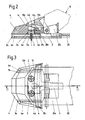
- FIG. 1 shows a part of a ski binding according to the invention in longitudinal section, the front ski binding part being cut along the line II in FIG. 3, FIG. 2 a section along the line II in FIG. 3, FIG. 3 a plan view of FIG. 2, with the sole holding-down device being omitted and FIGS. 4 to 7 details of further embodiments of the ski binding according to the invention.
- a ski binding designated in its entirety with 1 is for mounting on a ski by means of screws 2 with a base plate 3 for a a first ski binding part serving front jaws 10 and a mounting plate 5 for a sole plate 20 pivotable about a vertical axis.
- the base plate 3 has bores 3b for the screws 2 and on both sides extending in the longitudinal direction of the ski, upwardly projecting guide rails 3a.
- a bearing body 4 is mounted so as to be longitudinally displaceable but not detachable, side parts 4a of the bearing body 4 embracing or engaging around the guide rails 3a of the base plate 3 (see FIGS. 2 and 3).
- a guide groove 4b which runs parallel to the ski surface and transverse to the longitudinal axis of the ski, is excluded.
- the guide groove 4b has at its front end an upward extension 4b1.
- On the top of the bearing body 4 a downward and rearward sloping guide surface 4c is formed.
- a control nose 4d rises in the region of the longitudinal axis of the guide surface 4c.
- bores 4e are also provided for the screws 2, which bores 4e are aligned with the bores 3b in the base plate 3 when the ski binding 1 is in the ready-to-install position.
- the front area of the sole plate 20 is also shown, which is pivotally mounted in a known manner on a pivot 6 to be described in more detail later.
- the front end region of the sole plate 20 is designed as a bearing block 20a for the front jaw 10, which is only indicated here, with its control member 10a.
- the control member 10a is provided with bores 10b for the screws 2, which bores 10b in the ready-to-install position of the ski binding 1 are aligned with the bores 4e in the bearing body 4 and the bores 3b in the base plate 3.
- the front area of the bearing block 20a is designed as an extension 20b and has the shape of an inverted L in cross section.
- the extension 20b of the bearing block 20a engages in the guide groove 4b of the bearing body 4, with an upwardly projecting part 20c of the Approach 20b in the extension 4b1 of the guide groove 4b extends.
- the pivot 6 is firmly connected to the mounting plate 5 and supports the sole plate 20 by means of a sleeve 7.
- the rear end region of the mounting plate 5 is designed as a guide for the pivot plate 20 in a manner to be described in more detail.
- An intermediate element 5a and a control cam element 5b arranged above are firmly connected to the mounting plate 5, for example riveted.
- the front region of the cam element 5b is designed as a holding rail 5b 1 and overlaps a holding element 20 d which is connected to the sole plate 20 and is approximately U-shaped in cross section.
- the rear area of the cam element 5b is designed as a cam 5b2 for a heel holder 30 attached to the sole plate 20 and serving as a second ski binding part and cooperates with a control roller 30a connected to the heel holder 30.
- the heel holder 30, like a ski brake 40, is not the subject of the invention and is therefore not described in detail.
- the screws 2 for mounting the base plate 3 are inserted into the holes 4e of the bearing body 4 and the holes 3b of the base plate in such a way that they move the bearing body 4 relative to the base plate 3 during transport or assembly of the Prevent ski binding 1.
- the diameters of the heads 2a of the screws 2 are adapted to the diameters of the bores 4e.
- the screws 2 can also be held in the bores 4e of the bearing body 4 in the region of the shaft of the individual screws 2.
- the individual bores 4e of the bearing body 4 are provided with disk-shaped elements 9 made of a deformable material.
- the screws 2 can be screwed in without additional effort.
- the bushings or sleeves 8 can be provided with threads for the screws 2. Such a measure is not necessary when using self-tapping screws.
Abstract
Die Erfindung betrifft eine Vorrichtung zum Befestigen einer Lagerstelle eines Skibindungsteils auf einem Ski. Der Skibindungsteil weist eine mittels Schrauben auf dem Ski festlegbare Grundplatte auf, welche Grundplatte mit Bohrungen für die Schrauben versehen sind. Die Schrauben sind in den Bohrungen bereits im montagebereiten Zustand des Skibindungsteils gehalten und stehen an der Unterseite der Grundplatte mit ihren freien Endbereichen vor. Erfindungsgemäß ist der Skibindungsteil (10) unter Zwischenschaltung eines relativ zur Grundplatte (3) verschiebbaren Lagerkörpers (4) festlegbar, wobei sich die Schrauben (2) im montagebereiten Zustand auch in die Bohrungen (4e) des Lagerkörpers (4) erstrecken. Es ist weiters erfindungswesentlich, daß jede Schraube (2) in ihrer in dem Lagerkörper (4) vorgesehenen Bohrung (4e) gegen Herausfallen gesichert (gehalten) ist.The invention relates to a device for fastening a bearing point of a ski binding part on a ski. The ski binding part has a base plate which can be fixed on the ski by means of screws, which base plate is provided with holes for the screws. The screws are already held in the holes when the ski binding part is ready for installation and protrude from the underside of the base plate with its free end areas. According to the invention, the ski binding part (10) can be fixed with the interposition of a bearing body (4) which can be displaced relative to the base plate (3), the screws (2) also extending into the bores (4e) of the bearing body (4) when ready for installation. It is furthermore essential to the invention that each screw (2) is secured (held) in its bore (4e) provided in the bearing body (4) against falling out.
Description
Die Erfindung betrifft eine Schraubenverbindung nach dem Oberbegriff des Anspruches 1.The invention relates to a screw connection according to the preamble of
Vorrichtungen dieser Art sind in verschiedenen Formen bereits bekannt. Bei einer Lösung nach der DE-OS 23 59 489 werden die einzelnen Schrauben der Schraubenverbindung in ein verformbares Halteorgan eingesetzt, in welches die Schraube eingreift und in welchem sie gehalten ist, wogegen das verformbare Halteorgan gegen Rotation gesichert ist. Die bekannte Lösung weist verschiedene Ausführungsformen auf, ist jedoch mit dem Nachteil verbunden, daß die Halterung der Schraube eine zusätzliche Ausgestaltung zu erfahren hat, und daß das verformbare Halteorgan ein zusätzliches Bauelement bildet. Dadurch werden aber das Herstellungsverfahren und die Montage kompliziert, wobei zu beachten ist, daß die Mehraufwendungen der Technologie von der Anzahl der jeweils zur Verwendung gelangenden Schrauben abhängig sind.Devices of this type are already known in various forms. In a solution according to DE-OS 23 59 489, the individual screws of the screw connection are inserted into a deformable holding member in which the screw engages and in which it is held, whereas the deformable holding member is secured against rotation. The known solution has various embodiments, but is associated with the disadvantage that the mounting of the screw has to undergo an additional configuration and that the deformable holding member forms an additional component. This, however, complicates the manufacturing process and the assembly, it being noted that the additional expenditure of the technology depends on the number of screws used in each case.
Bei einer anderen bekannten Lösung nach der AT-PS 372.863 werden für das Festhalten der eingesetzten Schrauben in deren nicht montiertem Zustand Ansätze verwendet. Diese müssen unterschiedliche Radien aufweisen, wobei die Kreise der RAdien einander tangential berühren und die beiden Berührungspunkte der Kreise der beiden Ansätze relativ zueinander um 180° versetzt sind. Dadurch wird ebenso wie bei jenem Stand der Technik, aus dem bei dieser Lösung ausgegangen wurde, das Herstellungsverfahren für das Anbringen der Ansätze mit erhöhtem Zeit- und Kostenaufwand verbunden, wobei bei dem dort berücksichtigten Stand der Technik diese Aufwendungen noch höher sind.In another known solution according to AT-PS 372.863 approaches are used to hold the screws used in their unmounted state. These must have different radii, the circles of the radii touching each other tangentially and the two points of contact of the circles of the two approaches being offset relative to one another by 180 °. As with the prior art from which this solution was based, this means that the manufacturing process for attaching the approaches is associated with increased expenditure of time and money, these expenses being even higher in the prior art taken into account there.
Die in der DE-OS 27 32 099 vorgeschlagene Lösung verwendet einen gesonderten Halteteil zur Aufnahme der Schraube, wobei dieser Halteteil an seinen dem Kopf der Schraube zugewandten Flächen konisch geformt ist und mindestens einen Längsschlitz oder eine Sollbruchstelle aufweist, die zur Verformung und Zerstörung des Halteteils führt, so daß dieser bei Eindringen der Schraube abbricht, oder zumindest leicht entfernt werden kann. Hiezu wird also auch in diesem Fall die Verwendung eines zusätzlichen Bauelementes erforderlich, welches - im Gegensatz zu der an erster Stelle erwähnten Lösung - den gesonderten Halteteil nach der Montage nicht beinhaltet. Hinsichlich jener Lösungen, zu deren Verbesserung dieser Vorschlag dient, wird auf die in der DE-OS 27 32 099 angeführten Vorveröffentlichungen, insbesondere auf die NL-PS 128.844, hingewiesen.The solution proposed in DE-OS 27 32 099 uses a separate holding part for receiving the screw, this holding part being conically shaped on its surfaces facing the head of the screw and having at least one longitudinal slot or a predetermined breaking point, which leads to the deformation and destruction of the holding part, so that it breaks off when the screw penetrates, or at least can be easily removed. For this purpose, the use of an additional component is also necessary in this case, which - in contrast to the solution mentioned above - does not include the separate holding part after assembly. With regard to those solutions for the improvement of which this proposal serves, reference is made to the prior publications cited in DE-OS 27 32 099, in particular to NL-PS 128.844.
Aus der DE-OS 26 12 069 ist auch bekannt geworden, zur Betätigung der Befestigungsschrauben bei Vorderbacken die beiden Sohlenhalter mit einer Durchgangsöffnung für ein Werkzeug, z.B. für einen Schraubendreher, zu versehen.From DE-OS 26 12 069 it has also become known to actuate the fastening screws for toe pieces, the two sole holders with a through opening for a tool, e.g. for a screwdriver.
Ziel der Erfindung ist es, allen bekannten Lösungen gegenüber eine vereinfachte, sowohl im Herstellungsverfahren als auch in der Montage wenig aufwendige Lösung zu finden, bei der die Halterung einer Schraube zum Befestigen eines Skibindungsteils auf einem Ski ohne zusätzliche Bauteile und auch ohne besonders gestaltete Haltevorrichtungen ermöglicht wird und bei der die Schrauben während des Transportes der noch nicht montierten Skibindung und/oder während der Montage der Skibindung ein Verschieben des Lagerkörpers relativ zur Grundplatte verhindern.The aim of the invention is to find all known solutions compared to a simplified solution, which is not very expensive both in the production process and in assembly, in which the holding of a screw for fastening a ski binding part on a ski allows without additional components and also without specially designed holding devices is and in which the screws prevent the bearing body from moving relative to the base plate during the transport of the ski binding that has not yet been mounted and / or during the mounting of the ski binding.
Gelöst wird die gestellte Aufgabe erfindungsgemäß durch die kennzeichnenden Merkmale des Anspruches 1.The object is achieved according to the invention by the characterizing features of
Dadurch, daß jede Schraube in der ihr zugehörigen Bohrung in des Lagerkörpers gegen ein Herausfallen unmittelbar behalten ist, wird der Lagerkörper für die Zeit des Transports und der Montage relativ zur Grundplatte selbst gegen Rückstellungen und Erschütterungen sicher gehalten. Somit können die Skibindungsteile durch Einsetzen und Betätigen des Montagewerkzeuges, insbesondere, wenn die Schrauben, wie für sich bekannt, als selbstschneidende Schrauben ausgestaltet sind, sogleich montiert werden.Characterized in that each screw in its associated hole in the bearing body is kept from falling out immediately, the bearing body is safe for the time of transport and assembly relative to the base plate itself against resetting and vibrations held. The ski binding parts can thus be assembled immediately by inserting and operating the assembly tool, in particular if the screws, as is known per se, are designed as self-tapping screws.
Eine einfache und vorteilhafte Sicherung gegen das Herausfallen der Schrauben ist durch die Merkmale des Anspruches 2 gekennzeichnet. Diese Sicherung bedarf lediglich einer Abstimmung der Abmessungen der Schraubenköpfe an jene der Bohrungen.A simple and advantageous securing against the screws falling out is characterized by the features of
Beim Herstellen der Bohrungen der Grundplatte kann gemäß den Merkmalen des Anspruches 3 sogleich ein Gewinde eingeschnitten werden, wodurch ein Herausfallen der einzelnen Schrauben ebenfalls oder zusätzlich verhindert wird.When producing the bores of the base plate, a thread can be cut immediately according to the features of
Diese Maßnahme kann auch in Verbindung mit einem Einsatz, wie durch die Merkmale der Ansprüche 4 bis 6 gekennzeichnet ist, Verwendung finden.This measure can also be used in conjunction with an insert as characterized by the features of
Weitere Merkmale, Vorteile und Einzelheiten der Erfindung werden anhand der Zeichnung, die eine beispielsweise Ausführungsform zeigt, näher beschrieben. Dabei zeigen: Fig.1 Teile einer erfindungsgemäßen Skibindung im Längsschnitt, wobei der vordere Skibindungsteil nach der Linie I-I der Fig.3 geschnitten ist, Fig.2 einen Schnitt nach der Linie I-I der Fig.3, Fig.3 eine Draufsicht zu Fig.2, wobei der Sohlenniederhalter weggelassen wurde und die Fig.4 bis 7 Details weiterer Ausführungsformen der erfindungsgemäßen Skibindung.Further features, advantages and details of the invention are described in more detail with reference to the drawing, which shows an example embodiment. 1 shows a part of a ski binding according to the invention in longitudinal section, the front ski binding part being cut along the line II in FIG. 3, FIG. 2 a section along the line II in FIG. 3, FIG. 3 a plan view of FIG. 2, with the sole holding-down device being omitted and FIGS. 4 to 7 details of further embodiments of the ski binding according to the invention.
Die mit strichpunktierten Linien dargestellten Teile sind nicht Gegenstand der Erfindung und wurden nur der besseren Übersicht wegen gezeichnet.The parts shown with dash-dotted lines are not the subject of the invention and have only been drawn for the sake of clarity.
Eine in ihrer Gesamtheit mit 1 bezeichnete Skibindung ist für die Montage auf einem Ski mittels Schrauben 2 mit einer Grundplatte 3 für einen als ein erster Skibindungsteil dienenden Vorderbacken 10 und einer Montageplatte 5 für eine um eine Hochachse schwenkbare Sohlenplatte 20 ausgestattet. Die Grundplatte 3 weist Bohrungen 3b für die Schrauben 2 und an beiden Seiten sich in Skilängsrichtung erstreckende, nach oben ragende Führungsschienen 3a auf. Auf der Grundplatte 3 ist ein Lagerkörper 4 längsverschiebbar aber nicht abhebbar gelagert, wobei Seitenteile 4a des Lagerkörpers 4 die Führungsschienen 3a der Grundplatte 3 umgreifen bzw. untergreifen (s.Fig.2 und Fig.3). Am schuhseitigen Ende des Lagerkörpers 4 ist eine Führungsnut 4b, die parallel zur Skioberfläche und quer zur Skilängsachse verläuft, ausgenommen. Die Führungsnut 4b weist an ihrem vorderen Ende eine nach oben gerichtete Erweiterung 4b₁ auf. An der Oberseite des Lagerkörpers 4 ist eine nach unten und hinten schräge Führungsfläche 4c ausgebildet. Im Bereich der Längsachse der Führungsfläche 4c erhebt sich eine Steuernase 4d. In dem Lagerkörper 4 sind weiters Bohrungen 4e für die Schrauben 2 vorgesehen, welche Bohrungen 4e in der montagebereiten Stellung der Skibindung 1 mit den Bohrungen 3b in der Grundplatte 3 fluchten.A ski binding designated in its entirety with 1 is for mounting on a ski by means of
In der Zeichnung ist weiters der vordere Bereich der Sohlenplatte 20 dargestellt, welche in bekannter Weise an einem später noch näher zu beschriebenden Drehzapfen 6 schwenkbar gelagert ist. Der vordere Endbereich der Sohlenplatte 20 ist als Lagerbock 20a für den hier nur angedeuteten Vorderbacken 10 mit seinem Steuerglied 10a ausgebildet. Das Steuerglied 10a ist mit Bohrungen 10b für die Schrauben 2 versehen, welche Bohrungen 10b in der montagebereiten Stellung der Skibindung 1 mit den Bohrungen 4e in des Lagerkörpers 4 und den Bohrungen 3b in der Grundplatte 3 fluchten.In the drawing, the front area of the
Der vordere Bereich des Lagerbockes 20a ist als Ansatz 20b ausgebildet und hat im Querschnitt die Form eines seitenverkehrten liegenden L. Der Ansatz 20b des Lagerbockes 20a greift in die Führungsnut 4b des Lagerkörpers 4 ein, wobei sich ein nach oben ragender Teil 20c des Ansatzes 20b in die Erweiterung 4b₁ der Führungsnut 4b erstreckt.The front area of the
Der Drehzapfen 6 ist mit der Montageplatte 5 fest verbunden und trägt mittels einer Hülse 7 die Sohlenplatte 20. Der hintere Endbereich der Montageplatte 5 ist in noch näher zu beschreibender Weise als Führung für die Schwenkplatte 20 ausgebildet. Ein Zwischenelement 5a und ein darüber angeordnetes Steuerkurvenelement 5b sind mit der Montageplatte 5 fest verbunden, beispielsweise vernietet. Der vordere Bereich des Steuerkurvenelements 5b ist als Halteschiene 5b₁ ausgebildet und übergreift ein mit der Sohlenplatte 20 verbundenes im Querschnitt annähernd U-förmiges Halteelement 20d. Der hintere Bereich des Steuerkurvenelementes 5b ist als Steuerkurve 5b₂ für einen, an der Sohlenplatte 20 befestigten, als zweiter Skibindungsteil dienenden Fersenhalter 30 ausgebildet und wirkt mit einer mit dem Fersenhalter 30 verbundenen Steuerrolle 30a zusammen. Der Fersenhalter 30 ist ebenso wie eine Skibremse 40 nicht Gegenstand der Erfindung und daher nicht näher beschrieben.The
Wie besonders in Figur 2 erkennbar, sind die Schrauben 2 zur Montage der Grundplatte 3 so in die Bohrungen 4e des Lagerkörpers 4 und die Bohrungen 3b der Grundplatte gesteckt, daß sie ein Verschieben des Lagerkörpers 4 relativ zur Grundplatte 3 während des Transportes oder der Montage der Skibindung 1 verhindern. Um die Schrauben 2 gegen ein Herausfallen aus den Bohrungen 4e bzw. 3b zu sichern, sind die Durchmesser der Köpfe 2a der Schrauben 2 an die Durchmesser der Bohrungen 4e angepaßt. Das Halten der Schrauben 2 in den Bohrungen 4e des Lagerkörpers 4 kann auch im Bereich des Schaftes der einzelnen Schrauben 2 erfolgen. In diesem Fall sind die einzelnen Bohrungen 4e des Lagerkörpers 4 (wie Fig.6 zeigt) mit scheibenförmigen Elementen 9 aus einem deformierbaren Material versehen. Dadurch, daß die scheibenförmigen Elemente 9 jeweils einen Schlitz 9a aufweisen (s.Fig.7), ist das Eindrehen der Schrauben 2 ohne zusätzliche Kraftanstrengung möglich. Es ist aber ebenfalls oder zusätzlich möglich, die Bohrungen 3b in der Grundplatte 3 mit Gewindegängen 3c zu versehen, um damit die Schrauben 2 gegen ein Herausfallen zu sichern (s.Fig.5). Weiters wäre es möglich, die Schrauben 2 in den Bohrungen 3b der Grundplatte 3 durch Einsetzen geeigneter Buchsen oder Hülsen 8 in diese Bohrungen zu sichern (s.Fig.4). Dabei können die Buchsen oder Hülsen 8 mit Gewindegängen für die Schrauben 2 versehen sein. Bei Verwendung selbstschneidender Schrauben ist eine solche Maßnahme aber nicht erforderlich.As can be seen particularly in Figure 2, the
Claims (6)
Applications Claiming Priority (2)
| Application Number | Priority Date | Filing Date | Title |
|---|---|---|---|
| AT1914/86 | 1986-07-15 | ||
| AT0191486A AT385417B (en) | 1986-07-15 | 1986-07-15 | DEVICE FOR ATTACHING A STORAGE OF A SKI BINDING PART ON A SKI |
Publications (3)
| Publication Number | Publication Date |
|---|---|
| EP0253093A2 true EP0253093A2 (en) | 1988-01-20 |
| EP0253093A3 EP0253093A3 (en) | 1988-06-01 |
| EP0253093B1 EP0253093B1 (en) | 1990-12-05 |
Family
ID=3523747
Family Applications (1)
| Application Number | Title | Priority Date | Filing Date |
|---|---|---|---|
| EP87107035A Expired - Lifetime EP0253093B1 (en) | 1986-07-15 | 1987-05-15 | Device for fixing a bearing area of a ski binding part to a ski |
Country Status (5)
| Country | Link |
|---|---|
| US (1) | US4813700A (en) |
| EP (1) | EP0253093B1 (en) |
| JP (1) | JPS6324964A (en) |
| AT (1) | AT385417B (en) |
| DE (1) | DE3766552D1 (en) |
Cited By (1)
| Publication number | Priority date | Publication date | Assignee | Title |
|---|---|---|---|---|
| EP0464624A1 (en) * | 1990-07-06 | 1992-01-08 | HTM Sport- und Freizeitgeräte Aktiengesellschaft | Base-plate for ski bindings |
Families Citing this family (5)
| Publication number | Priority date | Publication date | Assignee | Title |
|---|---|---|---|---|
| AT395114B (en) * | 1987-12-11 | 1992-09-25 | Tyrolia Freizeitgeraete | FOR SKI BINDINGS OF SPECIFIC JAWS |
| DE8905417U1 (en) * | 1989-04-28 | 1990-05-31 | Marker Deutschland Gmbh, 8116 Eschenlohe, De | |
| DE8907527U1 (en) * | 1989-06-20 | 1990-08-16 | Marker Deutschland Gmbh, 8116 Eschenlohe, De | |
| FR2671288B1 (en) * | 1991-01-04 | 1993-03-12 | Salomon Sa | ALPINE SKI SAFETY ATTACHMENT. |
| FR2741275B1 (en) * | 1995-11-21 | 1998-01-23 | Look Fixations Sa | SKI BINDING EQUIPPED WITH A REMOVABLE BRAKE |
Citations (3)
| Publication number | Priority date | Publication date | Assignee | Title |
|---|---|---|---|---|
| CH512923A (en) * | 1970-07-22 | 1971-09-30 | Salomon Georges P J | Assembly ensuring the maintenance of a device for fixing a boot on a ski |
| FR2378201A1 (en) * | 1977-01-20 | 1978-08-18 | Salomon & Fils F | Ski-binding base mounting - with material removed rom around under-size hole so that walls collapse on tightening |
| FR2569990A1 (en) * | 1984-09-10 | 1986-03-14 | Salomon & Fils F | Ski binding having flexible piece and rigid insert |
Family Cites Families (11)
| Publication number | Priority date | Publication date | Assignee | Title |
|---|---|---|---|---|
| US2709470A (en) * | 1951-06-14 | 1955-05-31 | Illinois Tool Works | Screw and washer assembly |
| NL128844C (en) * | 1964-12-31 | |||
| FR2208692B1 (en) * | 1972-12-01 | 1976-08-20 | Salomon Georges P J | |
| DE2612069A1 (en) * | 1976-03-22 | 1977-09-29 | Marker Hannes | TOE FOR SAFETY SKI BINDINGS |
| FR2360385A1 (en) * | 1976-08-06 | 1978-03-03 | Beyl Jean Joseph Alfred | SUPPORT FOR RETAINING THE FIXING SCREWS ON A PART INTENDED TO BE FIXED BY MEANS OF THESE |
| AT359898B (en) * | 1977-04-15 | 1980-12-10 | Tyrolia Freizeitgeraete | SAFETY SKI BINDING |
| AT372863B (en) * | 1982-02-12 | 1983-11-25 | Tyrolia Freizeitgeraete | BASIC BODY, ESPECIALLY FOR SKI BINDINGS |
| AT381455B (en) * | 1983-10-21 | 1986-10-27 | Amf Sport Freizeitgeraete | ANTI-THEFT SECURITY FOR A SKI WITH A BINDING |
| AT379748B (en) * | 1983-12-19 | 1986-02-25 | Amf Sport Freizeitgeraete | SAFETY SKI BINDING |
| DE8410539U1 (en) * | 1984-04-04 | 1985-05-02 | Marker Patentverwertungsgesellschaft mbH, Baar | Device on components that can be screwed onto an object |
| DE3415272A1 (en) * | 1984-04-24 | 1985-10-31 | Marker Patentverwertungsgesellschaft mbH, Baar | SAFETY SKI BINDING WITH A SOLE PANEL |
-
1986
- 1986-07-15 AT AT0191486A patent/AT385417B/en not_active IP Right Cessation
-
1987
- 1987-05-15 DE DE8787107035T patent/DE3766552D1/en not_active Expired - Fee Related
- 1987-05-15 EP EP87107035A patent/EP0253093B1/en not_active Expired - Lifetime
- 1987-07-14 JP JP62174044A patent/JPS6324964A/en active Pending
- 1987-07-15 US US07/073,681 patent/US4813700A/en not_active Expired - Fee Related
Patent Citations (3)
| Publication number | Priority date | Publication date | Assignee | Title |
|---|---|---|---|---|
| CH512923A (en) * | 1970-07-22 | 1971-09-30 | Salomon Georges P J | Assembly ensuring the maintenance of a device for fixing a boot on a ski |
| FR2378201A1 (en) * | 1977-01-20 | 1978-08-18 | Salomon & Fils F | Ski-binding base mounting - with material removed rom around under-size hole so that walls collapse on tightening |
| FR2569990A1 (en) * | 1984-09-10 | 1986-03-14 | Salomon & Fils F | Ski binding having flexible piece and rigid insert |
Cited By (1)
| Publication number | Priority date | Publication date | Assignee | Title |
|---|---|---|---|---|
| EP0464624A1 (en) * | 1990-07-06 | 1992-01-08 | HTM Sport- und Freizeitgeräte Aktiengesellschaft | Base-plate for ski bindings |
Also Published As
| Publication number | Publication date |
|---|---|
| EP0253093B1 (en) | 1990-12-05 |
| US4813700A (en) | 1989-03-21 |
| JPS6324964A (en) | 1988-02-02 |
| ATA191486A (en) | 1987-09-15 |
| EP0253093A3 (en) | 1988-06-01 |
| AT385417B (en) | 1988-03-25 |
| DE3766552D1 (en) | 1991-01-17 |
Similar Documents
| Publication | Publication Date | Title |
|---|---|---|
| EP2501875B1 (en) | Device for dividing regions | |
| DE2359489B2 (en) | ||
| DE3824192C1 (en) | ||
| AT395911B (en) | SIGNAL GAUGE FOR HINGE ASSEMBLY | |
| EP0039765B1 (en) | Device for mounting flexible printing plates on the plate cylinder of rotary printing presses | |
| EP0229973B1 (en) | Fastening device for attaching a bicycle luggage carrier | |
| EP0253093B1 (en) | Device for fixing a bearing area of a ski binding part to a ski | |
| AT405657B (en) | DEVICE FOR FIXING WHEEL ARM | |
| DE3634118C2 (en) | ||
| EP1859752B1 (en) | Bone plate | |
| EP3412246B1 (en) | Holder for abutment blank for tooth implants | |
| DE3416262A1 (en) | PLASTIC HOLDING PART | |
| DE8529634U1 (en) | Frame with circuit boards | |
| EP0300148B1 (en) | Base-plate for ski-bindings | |
| DE4430975C1 (en) | Device with a fastening element secured against falling off on a body | |
| DE3343844C2 (en) | Luggage racks for two-wheeled vehicles | |
| EP0826403A2 (en) | Game apparatus for playgrounds for children or the like | |
| DE3327865C2 (en) | ||
| DE3940926C2 (en) | Removable door hinge for motor vehicle doors | |
| DE3206529C2 (en) | Fastening device for cutting elements | |
| DE20117305U1 (en) | Adjustable door or window hinge | |
| DE3614009C2 (en) | ||
| DE10035956A1 (en) | Rail clamp holder to fix rails for sliding door system to glass or masonry sub-construction; non-positively engages rail and rail holder around more than half of rail circumference | |
| DE3441204C2 (en) | ||
| AT395114B (en) | FOR SKI BINDINGS OF SPECIFIC JAWS |
Legal Events
| Date | Code | Title | Description |
|---|---|---|---|
| PUAI | Public reference made under article 153(3) epc to a published international application that has entered the european phase |
Free format text: ORIGINAL CODE: 0009012 |
|
| AK | Designated contracting states |
Kind code of ref document: A2 Designated state(s): CH DE FR LI |
|
| PUAL | Search report despatched |
Free format text: ORIGINAL CODE: 0009013 |
|
| AK | Designated contracting states |
Kind code of ref document: A3 Designated state(s): CH DE FR LI |
|
| 17P | Request for examination filed |
Effective date: 19880930 |
|
| 17Q | First examination report despatched |
Effective date: 19890630 |
|
| GRAA | (expected) grant |
Free format text: ORIGINAL CODE: 0009210 |
|
| AK | Designated contracting states |
Kind code of ref document: B1 Designated state(s): CH DE FR LI |
|
| REF | Corresponds to: |
Ref document number: 3766552 Country of ref document: DE Date of ref document: 19910117 |
|
| ET | Fr: translation filed | ||
| PLBE | No opposition filed within time limit |
Free format text: ORIGINAL CODE: 0009261 |
|
| STAA | Information on the status of an ep patent application or granted ep patent |
Free format text: STATUS: NO OPPOSITION FILED WITHIN TIME LIMIT |
|
| RAP2 | Party data changed (patent owner data changed or rights of a patent transferred) |
Owner name: TMC CORPORATION |
|
| 26N | No opposition filed | ||
| REG | Reference to a national code |
Ref country code: CH Ref legal event code: PUE Owner name: HTM SPORT- UND FREIZEITGERAETE GMBH |
|
| REG | Reference to a national code |
Ref country code: FR Ref legal event code: TP |
|
| PGFP | Annual fee paid to national office [announced via postgrant information from national office to epo] |
Ref country code: DE Payment date: 19930322 Year of fee payment: 7 |
|
| PGFP | Annual fee paid to national office [announced via postgrant information from national office to epo] |
Ref country code: CH Payment date: 19930518 Year of fee payment: 7 |
|
| REG | Reference to a national code |
Ref country code: CH Ref legal event code: PFA Free format text: HTM SPORT- UND FREIZEITGERAETE AKTIENGESELLSCHAFT |
|
| PGFP | Annual fee paid to national office [announced via postgrant information from national office to epo] |
Ref country code: FR Payment date: 19940427 Year of fee payment: 8 |
|
| PG25 | Lapsed in a contracting state [announced via postgrant information from national office to epo] |
Ref country code: LI Effective date: 19940531 Ref country code: CH Effective date: 19940531 |
|
| REG | Reference to a national code |
Ref country code: CH Ref legal event code: PL |
|
| PG25 | Lapsed in a contracting state [announced via postgrant information from national office to epo] |
Ref country code: DE Effective date: 19950201 |
|
| PG25 | Lapsed in a contracting state [announced via postgrant information from national office to epo] |
Ref country code: FR Effective date: 19960229 |
|
| REG | Reference to a national code |
Ref country code: FR Ref legal event code: ST |
|
| REG | Reference to a national code |
Ref country code: FR Ref legal event code: ST |