EP0253048B2 - Garment pressing machine - Google Patents
Garment pressing machine Download PDFInfo
- Publication number
- EP0253048B2 EP0253048B2 EP86890212A EP86890212A EP0253048B2 EP 0253048 B2 EP0253048 B2 EP 0253048B2 EP 86890212 A EP86890212 A EP 86890212A EP 86890212 A EP86890212 A EP 86890212A EP 0253048 B2 EP0253048 B2 EP 0253048B2
- Authority
- EP
- European Patent Office
- Prior art keywords
- plate
- pressing machine
- cover
- lower plate
- tensioning frame
- Prior art date
- Legal status (The legal status is an assumption and is not a legal conclusion. Google has not performed a legal analysis and makes no representation as to the accuracy of the status listed.)
- Expired - Lifetime
Links
- 239000000463 material Substances 0.000 claims description 10
- 238000010409 ironing Methods 0.000 abstract description 30
- 239000004744 fabric Substances 0.000 description 3
- 238000000034 method Methods 0.000 description 3
- XEEYBQQBJWHFJM-UHFFFAOYSA-N Iron Chemical compound [Fe] XEEYBQQBJWHFJM-UHFFFAOYSA-N 0.000 description 2
- 238000010586 diagram Methods 0.000 description 1
- 238000001035 drying Methods 0.000 description 1
- 229910052742 iron Inorganic materials 0.000 description 1
- 238000012986 modification Methods 0.000 description 1
- 230000004048 modification Effects 0.000 description 1
Images
Classifications
-
- D—TEXTILES; PAPER
- D06—TREATMENT OF TEXTILES OR THE LIKE; LAUNDERING; FLEXIBLE MATERIALS NOT OTHERWISE PROVIDED FOR
- D06F—LAUNDERING, DRYING, IRONING, PRESSING OR FOLDING TEXTILE ARTICLES
- D06F71/00—Apparatus for hot-pressing clothes, linen or other textile articles, i.e. wherein there is substantially no relative movement between pressing element and article while pressure is being applied to the article; Similar machines for cold-pressing clothes, linen or other textile articles
- D06F71/18—Apparatus for hot-pressing clothes, linen or other textile articles, i.e. wherein there is substantially no relative movement between pressing element and article while pressure is being applied to the article; Similar machines for cold-pressing clothes, linen or other textile articles specially adapted for pressing particular garments or parts thereof
- D06F71/28—Apparatus for hot-pressing clothes, linen or other textile articles, i.e. wherein there is substantially no relative movement between pressing element and article while pressure is being applied to the article; Similar machines for cold-pressing clothes, linen or other textile articles specially adapted for pressing particular garments or parts thereof for pressing sleeves, trousers, or other tubular garments or tubular parts of garments
- D06F71/29—Trousers
Definitions
- the invention relates to an ironing machine, each with an upper and lower plate, which are arranged such that they can be pressed against one another and have an ironing surface on their mutually facing sides, the upper plate being assigned a tensioning frame with a fabric cover and this tensioning frame being adjustable independently of the plate assigned to it is arranged.
- the upper and lower plates In ironing machines with upper and lower plates which can be pressed against one another and which have an ironing surface on their mutually facing sides, the upper and lower plates can each form a shaped iron body, which is provided with a steam supply.
- a disadvantage of known machines of this type e.g. US-A 3 501 857) is that when ironing goods which have different layers of material, e.g. the seam area of trouser legs, so-called footprints, i.e. form depressions that require ironing by hand.
- the frame In an ironing machine of the type mentioned at the outset, in which a clamping frame with a fabric cover that can be rotated about a horizontal axis and brought into a horizontal position is assigned to the upper plate (GB-A 335 341), the frame can be operated at the same level as the lower plate by actuating a foot pedal to be brought.
- the fabric cover is only used to protect the ironing material that is spread out before using the frame.
- the mobility of the frame by means of the foot pedal is intended to keep hands free in order to manipulate the items to be ironed and to be able to actuate the top plate. It follows that the stretching of the ironing goods is reserved for manual work.
- the invention has for its object to provide an arrangement in which before and during the actual ironing process the leveling of the items to be ironed is ensured.
- each of the top and bottom plates is assigned a tensioning frame with an elastically stretchable cover and is arranged to be adjustable independently of the top or bottom plate assigned to it parallel to the movement of its assigned plate and a tension directed from the center of the press plate towards the side edges thereof can be exerted from the tenter frame cover onto the ironing material, under the effect of which the ironing material is tensioned and held even before the top and bottom plates are closed.
- one, preferably both, clamping frames can be adjusted out of the plane of the ironing surface, so that the ironing material in contact with him or her is caused by the tension of the cover (s) stretching during adjustment, while pulling from the center of the press plate to the side edges, clamped and thereby kept flat when the top and bottom plates are subsequently closed and then the actual ironing takes place.
- This tension of the ironing material can also be maintained during drying by means of vacuum; so there are no more marks.
- the ironing machine has an upper plate 1, below which a lower plate 2 is located.
- These plates 1, 2 are expediently guided, adjustable parallel to one another, vertically one above the other, the top plate 1 preferably being able to be moved laterally away, in particular pivoting away, from the position shown in FIG enable.
- the top plate 1 is associated with a stretching frame 5 provided with a stretchable cover 3, and accordingly the bottom plate 2 is assigned a stretching frame 6 provided with a stretchable cover 4.
- each clamping frame 4 or 6 lies with an unstretched cover 3 or 5, approximately at the height of the ironing surface, which is formed by the facing serial surfaces of top and bottom plates 1 and 2.
- Each of the clamping frames 5, 6, between their covers 3 a pair of trousers 7 is movably supported on a schematically indicated vertical guide 8.
- An elastic stretch cord e.g. for ski pants is proven to be particularly cheap.
- the ironing machine can be provided in the usual way with a central control unit, not shown, from which corresponding, also not shown, pneumatic, in particular electropneumatic, or hydraulic actuating devices for actuating or adjusting the top and bottom plate 1, 2 and their associated clamping frame 5.6 are controllable.
- the legs 3, 4 of the tensioning frame 5, 6 are not only parallel to each other, but also parallel to the associated edges of the ironing surfaces, formed by the edges of the top and bottom plates 1, 2.
- the trousers 7 are placed on the cover 3 of the clamping frame 4 of the lower plate 2, and then the upper plate 1, together with the associated clamping frame 5 carrying the cover 3, is moved into the position above the lower plate 2 , as shown in Fig. 3.
- top plate 1 is lowered onto the bottom plate 2, as indicated by the vertical arrows in FIG. 4, and in doing so presses the ironed item, here the trousers 7, which is held stretched.
- the press plates 1, 2 are opened, i.e. the top plate 1, together with its tensioning frame 5 moving back into the starting position, is moved upward and possibly pivoted away, whereupon the trousers 7 can be removed from the cover 4 of the tensioning ram 6 also moved back into its starting position.
- the tensioning frame 5, 6 can, instead of as shown as two parallel rods, also be designed in the form of a U-bracket or a closed rectangular frame; in some cases it may be appropriate to train them according to the shape of the ironing material, e.g. B. sector-shaped or circular.
Abstract
Description
Die Erfindung bezieht sich auf eine Bügelmaschine mit je einer Ober- und Unterplatte, die gegeneinander preßbar angeordnet sind und an ihren einander zugekehrten Seiten eine Bügelfläche aufweisen, wobei der Oberplatte ein Spannrahmen mit einem Stoffbezug zugeordnet ist und dieser Spannrahmen unabhängig von der ihm zugeordneten Platte verstellbar angeordnet ist.The invention relates to an ironing machine, each with an upper and lower plate, which are arranged such that they can be pressed against one another and have an ironing surface on their mutually facing sides, the upper plate being assigned a tensioning frame with a fabric cover and this tensioning frame being adjustable independently of the plate assigned to it is arranged.
Bei Bügelmaschinen mit gegeneinanderpreßbar angeordneten Ober- und Unterplatten, die an ihren einander zugekehrten Seiten eine Bügelfläche aufweisen, können in üblicher Weise die Ober- und Unterplatte je einen Bügelformkörper bilden, der mit einer Dampfzuführung versehen ist. Nachteilig ist bei bekannten Maschinen dieser Art (z.B. US-A 3 501 857), daß beim Bügeln von Gut, das verschieden hohe Materiallagen aufweist, wie z.B. der Nahtbereich von Hosenbeinen, sogenannte Abdrükke entstehen, d.h. sich Vertiefungen ausbilden, die ein Nachbügeln von Hand erfordern.In ironing machines with upper and lower plates which can be pressed against one another and which have an ironing surface on their mutually facing sides, the upper and lower plates can each form a shaped iron body, which is provided with a steam supply. A disadvantage of known machines of this type (e.g. US-A 3 501 857) is that when ironing goods which have different layers of material, e.g. the seam area of trouser legs, so-called footprints, i.e. form depressions that require ironing by hand.
Bei einer Bügelmaschine der eingangs erwähnten Art, bei der der Oberplatte ein um eine horizontale Achse drehbarer, in eine horizontale Lage bringbarer Spannrahmen mit Stoffbezug zugeordnet ist (GB-A 335 341), kann durch Betätigen eines Fußpedals der Rahmen auf gleiches Niveau mit der Unterplatte gebracht werden. Der Stoffbezug dient nur dazu, das Bügelgut, das vor der Benutzung des Rahmens ausgebreitet ist, zu schützen. Die Bewegbarkeit des Rahmens mittels des Fußpedals bezweckt bei der bekannten Bügelmaschine, die Hände frei zu halten, um das Bügelgut manipulieren und die Oberplatte betätigen zu können. Daraus folgt, daß das Spannen des Bügelgutes der Handarbeit vorbehalten bleibt.In an ironing machine of the type mentioned at the outset, in which a clamping frame with a fabric cover that can be rotated about a horizontal axis and brought into a horizontal position is assigned to the upper plate (GB-A 335 341), the frame can be operated at the same level as the lower plate by actuating a foot pedal to be brought. The fabric cover is only used to protect the ironing material that is spread out before using the frame. In the known ironing machine, the mobility of the frame by means of the foot pedal is intended to keep hands free in order to manipulate the items to be ironed and to be able to actuate the top plate. It follows that the stretching of the ironing goods is reserved for manual work.
Die Erfindung stellt sich die Aufgabe, eine Anordnung zu schaffen, bei der vor und während des eigentlichen Bügelvorganges das Ebenliegen des Bügelgutes gewährleistet ist.The invention has for its object to provide an arrangement in which before and during the actual ironing process the leveling of the items to be ironed is ensured.
Die Lösung dieser Angabe erfolgt bei einer Bügelmaschine der eingangs genannten Art dadurch, daß jeder der Ober- und Unterplatten ein Spannrahmen mit einem elastisch dehnbaren Bezug zugeordnet und unabhängig von der ihm zugeordneten Ober- bzw. Unterplatte parallel zur Bewegung seiner zugeordneten Platte verstellbar angeordnet ist und vom Spannrahmenbezug auf das Bügelgut ein von der Mitte der Preßplatte zu deren Seitenkanten hin gerichteter Zug ausübbar ist, unter dessen Wirkung schon vor dem Schließen von Ober- bzw. Unterplatte das Bügelgut gespannt und eben gehalten wird. Somit kann vor dem Schließen von Ober- und Unterplatte ein, bevorzugt beide, Spannrahmen aus der Ebene der Bügelfläche heraus verstellt werden, so daß das mit ihm bzw. ihnen in Berührung stehende Bügelgut durch die Spannung des bzw. der sich beim Verstellen dehnenden Bezüge, unter Ausübung eines Zuges von der Mitte der Preßplatte aus zu deren Seitenkanten hin, mitgespannt und dadurch eben gehalten wird, wenn nachfolgend Ober- und Unterplatte geschlossen werden und dann das eigentliche Bügeln erfolgt. Diese Spannung des Bügelgutes kann auch während des Trocknens mittels Vakuum aufrechterhalten werden; es treten also keine Abdrücke mehr auf.This information is solved in an ironing machine of the type mentioned in the introduction in that each of the top and bottom plates is assigned a tensioning frame with an elastically stretchable cover and is arranged to be adjustable independently of the top or bottom plate assigned to it parallel to the movement of its assigned plate and a tension directed from the center of the press plate towards the side edges thereof can be exerted from the tenter frame cover onto the ironing material, under the effect of which the ironing material is tensioned and held even before the top and bottom plates are closed. Thus, before the top and bottom plates are closed, one, preferably both, clamping frames can be adjusted out of the plane of the ironing surface, so that the ironing material in contact with him or her is caused by the tension of the cover (s) stretching during adjustment, while pulling from the center of the press plate to the side edges, clamped and thereby kept flat when the top and bottom plates are subsequently closed and then the actual ironing takes place. This tension of the ironing material can also be maintained during drying by means of vacuum; so there are no more marks.
Wertere Einzelheiten und Vorteile der Erfindung ergeben sich aus der folgenden Beschreibung anhand eines in der Zeichnung schematisch dargestellten Ausführungsbeispieles; es zeigen:
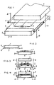
- Fig. 1 ein Schaubild der wesentlichen Teile der Bügelmaschine, nämlich je einer Ober- und Unterplatte als Preßplatten mit je einem zugeordneten Spannrahmen, und
- die Fig. 2 bis 4 die Stellungen dieser Teile zueinander, vor und während des Bügelvorganges.
- Fig. 1 is a diagram of the essential parts of the ironing machine, namely an upper and lower plate as press plates, each with an associated clamping frame, and
- 2 to 4, the positions of these parts to each other, before and during the ironing process.
Wie aus Fig. 1 ersichtlich, weist die Bügelmaschine eine Oberplatte 1 auf, unterhalb welcher sich eine Unterplatte 2 befindet. Zweckmäßig liegen diese Platten 1, 2, zueinander parallel verstellbar geführt, vertikal übereinander, wobei die Oberplatte 1 bevorzugt aus der in Fig. 1 ersichtlichen Lage seitlich wegbewegbar, insbesondere wegschwenkbar, angeordnet sein kann, um das ungehinderte Auflegen von Bügelgut auf die Unterplatte 2 zu ermöglichen.As can be seen from FIG. 1, the ironing machine has an
Der Oberplatte 1 ist ein mit einem dehnbaren Bezug 3 versehener Spannrahmen 5 zugeordnet, und entsprechend ist der Unterplatte 2 ein mit einem dehnbaren Bezug 4 versehener Spannrahmen 6 zugeordnet. Wie aus Fig. 2 erkenntlich, liegt jeder Spannrahmen 4 bzw. 6, und zwar mit ungedehntem Bezug 3 bzw. 5, etwa in der Höhe der Bügelfläche, die durch die einander zugekehrten Serienflächen von Ober- und Unterplatte 1 bzw. 2 gebildet ist.The
Jeder der Spannrahmen 5,6, zwischen deren Bezügen 3,4 als Bügelgut hier z.B. eine Hose 7, liegt, ist an einer schematisch angedeuteten Vertikalführung 8 beweglich gelagert.Each of the
Als Bezug für die Spannrahmen 5,6 hat sich ein elastischer Stretchcord, wie er z.B. für Skihosen gebraucht wird, als besonders günstig erwiesen.An elastic stretch cord, e.g. for ski pants is proven to be particularly cheap.
Die Bügelmaschine kann in üblicher Weise mit einer nicht dargestellten Zentralsteuereinheit versehen sein, von der aus entsprechende, ebenfalls nicht dargestellte, pneumatische, insbesondere elektropneumatische, oder hydraulische Stellvorrichtungen für das Betätigen bzw. die Verstellung von Ober- und Unterplatte 1, 2 und deren zugeordneten Spannrahmen 5,6 steuerbar sind.The ironing machine can be provided in the usual way with a central control unit, not shown, from which corresponding, also not shown, pneumatic, in particular electropneumatic, or hydraulic actuating devices for actuating or adjusting the top and
Wie ersichtlich, sind die den Bezug 3, 4 tragenden Schenkel der Spannrahmen 5,6 nicht nur zueinander parallel, sondern auch parallel zu den zugeordneten Kanten der Bügelflächen, gebildet durch die Ränder von Ober- und Unterplatte 1,2, angeordnet.As can be seen, the
Die Wirkungsweise dieser Anordnung ist folgende:This arrangement works as follows:
Wie aus Fig. 2 ersichtlich, wird die Hose 7 auf den Bezug 3 des Spannrahmens 4 der Unterplatte 2 aufgelegt, und dann wird die Oberplatte 1, zusammen mit dem zugeordneten, den Bezug 3 tragenden Spannrahmen 5, in die Stellung über die Unterplatte 2 verfahren, wie in Fig. 3 dargestellt.As can be seen from FIG. 2, the
Hierauf erfolgt gleichzeitig eine Verstellung der beiden Spannrahmen 5,6 an den Führungen 8 nach unten, wie durch vertikale Pfeile in Fig. 3 veranschaulicht. Dabei werden die Bezüge 3, 4 gedehnt, d.h. sie gleiten mit ihren Randbereichen über die Ränder der Unterplatte 2 hinweg nach unten und üben somit, von der Mitte der Unterplatte 1, in der sich die Hosennähte befinden, ausgehend in Richtung auf die Bügelfalten der Hose 7 hin einen durch horizontale Pfeile angedeuteten Zug auf diese aus, sodaß diese eben gespannt gehalten wird.This is followed simultaneously by an adjustment of the two
Nun wird die Oberplatte 1 auf die Unterplatte 2 abgesenkt, wie durch die vertikalen Pfeile in Fig. 4 angedeutet, und preßt dabei das gestreckt gehaltene Bügelgut, hier die Hose 7.Now the
Nach dem Bügelvorgang erfolgt das Öffnen der Preßplatten 1,2, d.h. die Oberplatte 1 wird samt ihrem sich in die Ausgangsstellung zurückbewegenden Spannrahmen 5 nach oben verfahren und allenfalls weggeschwenkt, worauf vom Bezug 4 des ebenfalls in seine Ausgangsstellung zurückbewegten Spannrhamens 6 die Hose 7 abnehmbar ist.After the ironing process, the
Im Rahmen der Erfindung sind Abänderungen an dem beschriebenen Ausführungsbeispiel möglich. So kann es in manchen Fällen genügen, auch bloß eine der beiden Preßplatten 1,2 mit einem Spannrahmen auszustatten. Das Strecken des Bügelgutes könnte, anders als beim erläuterten Beispiel, auch dadurch erfolgen, daß beide Spannrahmen nach oben über die Höhe der Bügelfläche verstellt werden. Auch muß die Oberplatte 1 nicht unbedingt zusätzlich seitlich zur Unterplatte 2 verfahrbar angeord net sein. Ferner können nach Bedarf die einzelnen Arbeits- und Verstellschritte der Teile der Bügelmaschine programmgesteuert sein.Modifications to the described embodiment are possible within the scope of the invention. So in some cases it may be sufficient to provide only one of the two
Die Spannrahmen 5,6 können, anstelle wie dargestellt als zwei parallele Stangen, auch in Form eines U-Bügels oder eines geschlossenen rechtekkigen Rahmens ausgebildet sein,; in manchen Fällen mag es zweckmäßig sein, sie entsprechend der Form des Bügelgutes auszubilden, z. B. sektorförmig oder kreisrund.The
Claims (7)
Priority Applications (5)
| Application Number | Priority Date | Filing Date | Title |
|---|---|---|---|
| AT86890212T ATE44057T1 (en) | 1986-07-18 | 1986-07-18 | IRONING MACHINE. |
| EP86890212A EP0253048B2 (en) | 1986-07-18 | 1986-07-18 | Garment pressing machine |
| DE8686890212T DE3663964D1 (en) | 1986-07-18 | 1986-07-18 | Garment pressing machine |
| CA000542379A CA1272947A (en) | 1986-07-18 | 1987-07-17 | Ironing machine |
| US07/074,768 US4819350A (en) | 1986-07-18 | 1987-07-17 | Ironing machine |
Applications Claiming Priority (1)
| Application Number | Priority Date | Filing Date | Title |
|---|---|---|---|
| EP86890212A EP0253048B2 (en) | 1986-07-18 | 1986-07-18 | Garment pressing machine |
Publications (3)
| Publication Number | Publication Date |
|---|---|
| EP0253048A1 EP0253048A1 (en) | 1988-01-20 |
| EP0253048B1 EP0253048B1 (en) | 1989-06-14 |
| EP0253048B2 true EP0253048B2 (en) | 1994-12-07 |
Family
ID=8196575
Family Applications (1)
| Application Number | Title | Priority Date | Filing Date |
|---|---|---|---|
| EP86890212A Expired - Lifetime EP0253048B2 (en) | 1986-07-18 | 1986-07-18 | Garment pressing machine |
Country Status (5)
| Country | Link |
|---|---|
| US (1) | US4819350A (en) |
| EP (1) | EP0253048B2 (en) |
| AT (1) | ATE44057T1 (en) |
| CA (1) | CA1272947A (en) |
| DE (1) | DE3663964D1 (en) |
Families Citing this family (13)
| Publication number | Priority date | Publication date | Assignee | Title |
|---|---|---|---|---|
| US5359792A (en) * | 1991-09-10 | 1994-11-01 | Matsushita Electric Industrial Co., Ltd. | Free standing, upright clothes press |
| DE4322493A1 (en) * | 1993-07-06 | 1995-01-12 | Harald Engel | Tensioning and ironing device for pants envelopes and pocket flaps and their use |
| DE9313979U1 (en) * | 1993-09-15 | 1993-12-02 | Brisay Maschinen Gmbh | Device for separately folding and ironing the edge areas of two pieces of fabric sewn together |
| DE4409876C1 (en) * | 1994-03-22 | 1995-05-18 | Harald Engel | Ironing machine yielding items of improved appearance |
| JP2002191900A (en) * | 2000-12-27 | 2002-07-10 | Miyata Koki:Kk | Method and device for shaping and finishing texture |
| DE102009015001A1 (en) | 2009-03-26 | 2010-09-30 | Brisay Maschinen Gmbh | Ironing press cover for use in trousers press for stretching trousers to be ironed, has elastic section comprising two elastic strips that extend along strip longitudinal directions that run perpendicular to each other |
| CN101824739B (en) * | 2010-05-18 | 2011-11-02 | 中山益达服装有限公司 | Loop ironing press |
| KR102099175B1 (en) | 2013-07-17 | 2020-05-22 | 엘지전자 주식회사 | Laundry Treating Apparatus |
| KR102099179B1 (en) | 2013-12-05 | 2020-04-09 | 엘지전자 주식회사 | Laundry Treating Apparatus |
| US10081905B2 (en) | 2014-01-09 | 2018-09-25 | Modiron, LLC | Ironing device |
| EP3034684B1 (en) * | 2014-12-19 | 2017-10-04 | LG Electronics Inc. | Clothes treatment apparatus |
| JP2016150177A (en) * | 2015-02-19 | 2016-08-22 | 株式会社三幸社 | Medium iron of trouser press and medium iron cover |
| CN112981890B (en) * | 2021-02-04 | 2022-06-14 | 郑州市娅丽达服饰有限公司 | Dress designing clothes ironing device |
Family Cites Families (10)
| Publication number | Priority date | Publication date | Assignee | Title |
|---|---|---|---|---|
| US1392289A (en) * | 1918-07-05 | 1921-10-04 | American Laundry Mach Co | Garment-press and steaming mechanism |
| GB281074A (en) * | 1926-11-08 | 1927-12-01 | Charles Clark | Improvements in garment pressing machines |
| US1725514A (en) * | 1927-10-24 | 1929-08-20 | Harootniain Ogasap | Pressing machine for clothes |
| US1835254A (en) * | 1929-09-16 | 1931-12-08 | Prosperity Co Inc | Work holding means for pressing machines |
| FR1528869A (en) * | 1967-05-03 | 1968-06-14 | Anciens Etablissements P Lemai | Ironing process, in particular of clothes, and press allowing the implementation |
| US3501857A (en) * | 1968-06-11 | 1970-03-24 | George Schlemon | Garment treatment method |
| US3665624A (en) * | 1970-08-21 | 1972-05-30 | Charles D Briddell | Portable garment pressing device |
| US3722115A (en) * | 1971-07-12 | 1973-03-27 | Mc Graw Edison Co | Garment press |
| US3835559A (en) * | 1972-03-27 | 1974-09-17 | G Kotter | Machine for ironing trousers |
| GB1493581A (en) * | 1975-09-19 | 1977-11-30 | Ibis Engineers Ltd | Garment pressing machines |
-
1986
- 1986-07-18 DE DE8686890212T patent/DE3663964D1/en not_active Expired
- 1986-07-18 AT AT86890212T patent/ATE44057T1/en not_active IP Right Cessation
- 1986-07-18 EP EP86890212A patent/EP0253048B2/en not_active Expired - Lifetime
-
1987
- 1987-07-17 CA CA000542379A patent/CA1272947A/en not_active Expired
- 1987-07-17 US US07/074,768 patent/US4819350A/en not_active Expired - Fee Related
Also Published As
| Publication number | Publication date |
|---|---|
| ATE44057T1 (en) | 1989-06-15 |
| EP0253048A1 (en) | 1988-01-20 |
| CA1272947A (en) | 1990-08-21 |
| EP0253048B1 (en) | 1989-06-14 |
| DE3663964D1 (en) | 1989-07-20 |
| US4819350A (en) | 1989-04-11 |
Similar Documents
| Publication | Publication Date | Title |
|---|---|---|
| EP0253048B2 (en) | Garment pressing machine | |
| DE1274062B (en) | Ironing press for pants | |
| DE1150042B (en) | Ironing press for pants | |
| DE3341487A1 (en) | Device for stretching mocassins | |
| DE10019383B4 (en) | Device for transporting a flat piece of goods | |
| AT388189B (en) | IRONING MACHINE | |
| DE2847805A1 (en) | METHOD AND DEVICE FOR STEAM IRONING OF THE HEM AREAS OF TUBE-SHAPED CLOTHES | |
| DE2435366B2 (en) | Ironing machine | |
| DE3535837C2 (en) | ||
| DE3409943C1 (en) | Device for skinning skins | |
| DE4409876C1 (en) | Ironing machine yielding items of improved appearance | |
| DE632607C (en) | Device for ironing items of clothing or the like. | |
| DE1460996A1 (en) | Method and device for ironing trousers | |
| DE2250678A1 (en) | PROCEDURE FOR THE MECHANICAL PLUGGING OF BAGS, IN PARTICULAR VALVE BOTTOM BAGS, ON THE NECK OF FILLING MACHINES AND MACHINE FOR PERFORMING THE PROCEDURE | |
| DE932836C (en) | Method and apparatus for forming cigar rolls | |
| DE1296120B (en) | Trouser ironing machine for smoothing trousers | |
| DE219798C (en) | ||
| DE1125399B (en) | Method and device for simultaneous press ironing of the sleeves of garments that are open on one side | |
| DE255731C (en) | ||
| DE483281C (en) | Folding machine for handkerchiefs u. like | |
| DE2646764A1 (en) | METHOD AND DEVICE FOR IRONING PANTS | |
| DE1785188B2 (en) | Method and device for producing a shoe on a device having a stretch bar | |
| DE2644695A1 (en) | DEVICE FOR THE TRANSFER OF ARTICLES TO AN AUTOMATIC ASSEMBLY MACHINE EQUIPPED WITH AN INSERTION SLIDE AND METHOD FOR TRANSFER OF ARTICLES TO SUCH MACHINE | |
| DE958195C (en) | Double-sided ironing press for shirts u. like items of clothing | |
| DE906908C (en) | Method and device for polishing zippers |
Legal Events
| Date | Code | Title | Description |
|---|---|---|---|
| PUAI | Public reference made under article 153(3) epc to a published international application that has entered the european phase |
Free format text: ORIGINAL CODE: 0009012 |
|
| AK | Designated contracting states |
Kind code of ref document: A1 Designated state(s): AT BE CH DE FR GB IT LI LU NL SE |
|
| 17P | Request for examination filed |
Effective date: 19880127 |
|
| 17Q | First examination report despatched |
Effective date: 19881020 |
|
| GRAA | (expected) grant |
Free format text: ORIGINAL CODE: 0009210 |
|
| AK | Designated contracting states |
Kind code of ref document: B1 Designated state(s): AT BE CH DE FR GB IT LI LU NL SE |
|
| PG25 | Lapsed in a contracting state [announced via postgrant information from national office to epo] |
Ref country code: SE Effective date: 19890614 Ref country code: NL Effective date: 19890614 Ref country code: BE Effective date: 19890614 |
|
| REF | Corresponds to: |
Ref document number: 44057 Country of ref document: AT Date of ref document: 19890615 Kind code of ref document: T |
|
| PG25 | Lapsed in a contracting state [announced via postgrant information from national office to epo] |
Ref country code: AT Effective date: 19890718 |
|
| REF | Corresponds to: |
Ref document number: 3663964 Country of ref document: DE Date of ref document: 19890720 |
|
| PG25 | Lapsed in a contracting state [announced via postgrant information from national office to epo] |
Ref country code: LU Free format text: LAPSE BECAUSE OF NON-PAYMENT OF DUE FEES Effective date: 19890731 Ref country code: LI Effective date: 19890731 Ref country code: CH Effective date: 19890731 |
|
| ITF | It: translation for a ep patent filed |
Owner name: MANZONI & MANZONI |
|
| ET | Fr: translation filed | ||
| GBT | Gb: translation of ep patent filed (gb section 77(6)(a)/1977) | ||
| NLV1 | Nl: lapsed or annulled due to failure to fulfill the requirements of art. 29p and 29m of the patents act | ||
| PLBI | Opposition filed |
Free format text: ORIGINAL CODE: 0009260 |
|
| REG | Reference to a national code |
Ref country code: CH Ref legal event code: PL |
|
| 26 | Opposition filed |
Opponent name: HOFFMAN MASCHINENBAU GMBH Effective date: 19900313 |
|
| ITPR | It: changes in ownership of a european patent |
Owner name: CESSIONE;HARALD ENGEL |
|
| REG | Reference to a national code |
Ref country code: FR Ref legal event code: TP |
|
| PUAH | Patent maintained in amended form |
Free format text: ORIGINAL CODE: 0009272 |
|
| STAA | Information on the status of an ep patent application or granted ep patent |
Free format text: STATUS: PATENT MAINTAINED AS AMENDED |
|
| 27A | Patent maintained in amended form |
Effective date: 19941207 |
|
| AK | Designated contracting states |
Kind code of ref document: B2 Designated state(s): AT BE CH DE FR GB IT LI LU NL SE |
|
| GBTA | Gb: translation of amended ep patent filed (gb section 77(6)(b)/1977) |
Effective date: 19950308 |
|
| ET3 | Fr: translation filed ** decision concerning opposition | ||
| PGFP | Annual fee paid to national office [announced via postgrant information from national office to epo] |
Ref country code: GB Payment date: 20010710 Year of fee payment: 16 |
|
| PGFP | Annual fee paid to national office [announced via postgrant information from national office to epo] |
Ref country code: FR Payment date: 20010717 Year of fee payment: 16 |
|
| PGFP | Annual fee paid to national office [announced via postgrant information from national office to epo] |
Ref country code: DE Payment date: 20010924 Year of fee payment: 16 |
|
| REG | Reference to a national code |
Ref country code: GB Ref legal event code: IF02 |
|
| PG25 | Lapsed in a contracting state [announced via postgrant information from national office to epo] |
Ref country code: GB Free format text: LAPSE BECAUSE OF NON-PAYMENT OF DUE FEES Effective date: 20020718 |
|
| PG25 | Lapsed in a contracting state [announced via postgrant information from national office to epo] |
Ref country code: DE Free format text: LAPSE BECAUSE OF NON-PAYMENT OF DUE FEES Effective date: 20030201 |
|
| GBPC | Gb: european patent ceased through non-payment of renewal fee |
Effective date: 20020718 |
|
| PG25 | Lapsed in a contracting state [announced via postgrant information from national office to epo] |
Ref country code: FR Free format text: LAPSE BECAUSE OF NON-PAYMENT OF DUE FEES Effective date: 20030331 |
|
| REG | Reference to a national code |
Ref country code: FR Ref legal event code: ST |
|
| PG25 | Lapsed in a contracting state [announced via postgrant information from national office to epo] |
Ref country code: IT Free format text: LAPSE BECAUSE OF NON-PAYMENT OF DUE FEES;WARNING: LAPSES OF ITALIAN PATENTS WITH EFFECTIVE DATE BEFORE 2007 MAY HAVE OCCURRED AT ANY TIME BEFORE 2007. THE CORRECT EFFECTIVE DATE MAY BE DIFFERENT FROM THE ONE RECORDED. Effective date: 20050718 |