EP0253000A1 - Machine protective system - Google Patents
Machine protective system Download PDFInfo
- Publication number
- EP0253000A1 EP0253000A1 EP86109368A EP86109368A EP0253000A1 EP 0253000 A1 EP0253000 A1 EP 0253000A1 EP 86109368 A EP86109368 A EP 86109368A EP 86109368 A EP86109368 A EP 86109368A EP 0253000 A1 EP0253000 A1 EP 0253000A1
- Authority
- EP
- European Patent Office
- Prior art keywords
- machine
- memory
- circuit
- sensor
- mat
- Prior art date
- Legal status (The legal status is an assumption and is not a legal conclusion. Google has not performed a legal analysis and makes no representation as to the accuracy of the status listed.)
- Granted
Links
Images
Classifications
-
- F—MECHANICAL ENGINEERING; LIGHTING; HEATING; WEAPONS; BLASTING
- F16—ENGINEERING ELEMENTS AND UNITS; GENERAL MEASURES FOR PRODUCING AND MAINTAINING EFFECTIVE FUNCTIONING OF MACHINES OR INSTALLATIONS; THERMAL INSULATION IN GENERAL
- F16P—SAFETY DEVICES IN GENERAL; SAFETY DEVICES FOR PRESSES
- F16P3/00—Safety devices acting in conjunction with the control or operation of a machine; Control arrangements requiring the simultaneous use of two or more parts of the body
- F16P3/12—Safety devices acting in conjunction with the control or operation of a machine; Control arrangements requiring the simultaneous use of two or more parts of the body with means, e.g. feelers, which in case of the presence of a body part of a person in or near the danger zone influence the control or operation of the machine
-
- F—MECHANICAL ENGINEERING; LIGHTING; HEATING; WEAPONS; BLASTING
- F16—ENGINEERING ELEMENTS AND UNITS; GENERAL MEASURES FOR PRODUCING AND MAINTAINING EFFECTIVE FUNCTIONING OF MACHINES OR INSTALLATIONS; THERMAL INSULATION IN GENERAL
- F16P—SAFETY DEVICES IN GENERAL; SAFETY DEVICES FOR PRESSES
- F16P3/00—Safety devices acting in conjunction with the control or operation of a machine; Control arrangements requiring the simultaneous use of two or more parts of the body
- F16P3/18—Control arrangements requiring the use of both hands
- F16P3/20—Control arrangements requiring the use of both hands for electric control systems
Definitions
- the invention relates to a machine protection circuit according to the preamble of patent claim 1.
- the known safety devices for machines have the disadvantage that they are severe disabilities train the operator and yet often do not work satisfactorily, especially in the event of a fault.
- the invention has for its object to provide a machine protection circuit according to the preamble of claim 1, the detection of people approaching the machine with certainty and has a high inherent error safety.
- a contact mat is laid in the danger area, which must not be entered while the machine is running, which provides an electrical signal for as long as it is entered by a person.
- a dynamically reacting sensor that detects changes in status in the hazardous area. Such changes in state result, for example, when a person enters the danger zone. In this case, the sensor generates a short-term signal due to the change in state, which is evaluated in addition to the signal of the step mat. If either the step mat or the dynamic sensor responds (or if both respond together), the corresponding memory is set. The memory remains in the set state even when the triggering signal has ended.
- the safety circuit can be triggered by either of the two memories to stop the machine.
- a special feature of the invention is that the devices that recognize the entry into the hazardous area of the machine are based on different operating principles. If the environmental influences as a result of any If events make one of the detection devices ineffective, the other detection device remains in operation. The same applies if the sensitivity of a detection device is temporarily reduced for some reason. In these cases, the other detection device ensures that a proper shutdown takes place.
- the (dynamic) sensor reacting to changes in state is preferably a sensor mat which consists of several plastic layers.
- a sensor mat When such a sensor mat is exposed to pressure, electrical charge carriers are displaced so that a change in potential can be determined on an electrode which is connected to one of the plastic layers.
- Such a sensor mat has the advantage that it does not react to static loads.
- the machine itself or a device required in the vicinity of the machine can be placed on it without a signal being generated as long as the object in question is not moved.
- Such a sensor mat is therefore particularly suitable for the close range of the machine. It is possible to place the machine itself or other parts on the sensor mat.
- the contact mat which should normally not be exposed to any stress, is more suitable for monitoring the wider environment of the machine.
- both mats contact mat and dynamic sensor mat
- both mats can overlap or overlap, but both mats can also be nested in such a way that they do not overlap, with one mat surrounding the other.
- the relay has current flowing through it, as long as none of the Detection devices has addressed and the machine should continue to run.
- the relay in question is de-energized because the stop signal for this relay coming from the memory then fails to appear.
- the circuit therefore has a high level of intrinsic failure safety because it switches off the machine not only when a detection device responds, but also when a defect, a line break or a short circuit occurs.
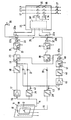
- a block diagram of the machine protection circuit is shown in the drawing.
- a contact mat 10 and a sensor mat 11 are laid on the floor a step mat are united.
- the contact mat 10 consists of two conductor tracks which are electrically insulated from one another, but come into contact with one another when they are pressed together by a load, which is indicated by the switch symbol 12.
- the output line 13 of the contact mat 10 is connected to ground potential when the contact mat 10 is loaded.
- the sensor mat 11 is laid in the hazardous area, which consists of several plastic sheets lying one on top of the other, one of which is at ground potential and while the output line 14 leads to the monitoring circuit.
- the outer foils of the foil package are provided with a metal coating and the two metal coatings are connected to one another by a high-resistance resistor 15.
- the contact mat 10 and the sensor mat 11 form a common step mat which must be entered to reach the machine and cannot be skipped.
- the foot mat is wide enough to ensure that the machine comes to a standstill in good time, so that a person entering the foot mat cannot reach into the machine while it is still running.
- the signal of the output line 14 of the sensor mat 11 is fed via a capacitor 16 and an impedance converter 17 to a threshold switch 18 which generates an output signal when the signal of the sensor mat exceeds a predetermined threshold value.
- the output of the threshold switch 18 is connected via a diode 19 to the input of the first memory 20, which is designed as a flip-flop.
- the input signal is fed to the dynamic input of the flip-flop, which tilts into the set state when a pulse is received and can be reset by a signal at its reset input R.
- the output of the flip-flop 20 is connected to the driver circuit 21, which is a transistor circuit, the structure of which is not specified in detail.
- the driver circuit 21 contains a resistor 22, via which its input line is connected to the positive pole of the supply voltage.
- the input of the driver circuit 21 sets is at plus potential if it is not forcibly set to another potential by the output of the memory 20.
- positive potential corresponds to a logic "1" signal
- ground potential corresponds to logic "0" signal.
- the output of the driver circuit 21 controls the relay 23.
- all relay contacts are shown in the idle state, that is to say when the relay is de-energized.
- the relay 23 has a normally open contact 23a (when the relay is energized) and a normally closed contact 23b (when the relay is energized).
- the normally open contact 23a is in a circuit
- the safety circuit 24 and the normally closed contact 23b is in a series circuit 25.
- the signal of the output line 14 of the sensor mat 11 is also fed via a second threshold switch 26 and a diode 27 to the anode of the diode 19, which is connected to the input of the memory 20.
- the response threshold of the threshold switch 26 is higher than that of the threshold switch 18.
- the threshold switch 26 does not respond to a signal generated by stepping on the step mat, but responds to short circuit and interruption of the output line 14, for example as a result of sabotage. He monitors whether the voltage on line 14 is within a voltage window that has a lower and an upper limit.
- the signal of the output line 13 of the contact mat 10 is fed to a threshold switch 28, the output of which is connected via a diode 29 to the input of the memory 30.
- the memory 30 is designed in the same way as the memory 20. Its output is connected to the driver circuit 31, which is designed in the same way as the driver circuit 21 and which controls the relay 32.
- the relay 32 has a normally open contact 32a, which is in a circuit of the safety circuit 24, and a normally closed contact 32b, which is contained in the series circuit 25.
- the safety circuit 24 is a commercially available two-hand safety relay that can interrupt the supply lines L1, L2 and L3 of the machine.
- the safety circuit 24 has two relays 33 and 34, each of which closes a three-pole mains switch 35 and 36 in the excited state.
- the manually operated main switch 37 of the machine is located between the safety circuit 24 and the machine.
- the safety circuit 24 has control electronics 38 which are controlled by the respective state of the normally open contacts 23a and 32a and which in turn controls the relays 33 and 34.
- the normally open contacts 23a and 32a which are manually operated in a two-hand safety relay, must be closed within 0.5 seconds, that is to say almost simultaneously will. As soon as at least one of the working contacts is opened, the safety circuit 24 switches off the machine.
- the series connection is connected via the normally open contact 40a of the further relay 40 to the reset inputs R of the two memories 20 and 30, so that these memories are reset when the contacts 23b, 32b and 40a are all closed when the reset switch 39 is actuated.
- the outputs of the threshold switches 18, 26 and 28 are each connected to a common line 44 via a diode 41, 42 and 43, respectively, which leads to the input of an impedance converter 45.
- the output signal of the impedance converter 45 controls the relay 40 via the threshold switch 46 and the driver circuit 47, which is designed in the same way as the driver circuit 21.
- a voltage pulse generated by pressure change on the sensor mat 11 passes via the capacitor 16 and the impedance converter 17 to the threshold switch 18, which then generates a square-wave pulse. Characterized in that a pulse is supplied to the memory 20 via the diode 19, this memory is set, ie a "1" signal is produced at its output. The memory 20 maintains the set state until it receives ground potential at its reset input R. The relay 23 is energized as long as a "0" signal is present at the output of the memory 20; if the memory 20 is set against it, there is a "1" signal at its output, as a result of which the relay 23 drops out.
- the relay 23 Since the input of the driver circuit 21 is pulled to a "1" signal via the resistor 22 if there is no "0" signal at the output of the memory 20, the relay 23 drops out even if one of the leads or supply lines of the driver circuit 21 upstream components is interrupted. The relay 23 thus drops out whenever a voltage pulse has been generated by the sensor mat 11 or when a supply line has been interrupted or short-circuited.
- a short circuit generated by static pressure on the contact mat 10 leads to a "1" signal at the output of the threshold circuit 28.
- the memory 30 is set and the driver 31 de-energizes the relay 32.
- the relay 32 therefore drops out whenever a short circuit is generated by the contact mat 10 or when the supply line to the contact mat has been interrupted.
- the safety circuit 24 switches off the machine.
- the safety circuit connects the machine to the supply lines L1, L2 and L3 only when both relays 23 and 32 are energized. This is only the case if the step mat, which consists of the contact mat 10 and the sensor mat 11, has not been walked on and the signal lines are error-free. If a "1" signal occurs at the output of a threshold switch, the machine is immediately switched off by the safety circuit 24 and remains switched off due to the function of the memories 20 and 30.
- the reset switch 39 which is preferably designed as a key switch.
- a prerequisite for switching on again is that when entering the step mat 10, 11 both relays 23 and 32 have dropped out and that the step mat is no longer loaded at the current time. This is checked by the threshold switch 46 which receives no signal via the OR circuit consisting of the diodes 41, 42 and 43 when the step mat is relieved. Only in this case, the relay 40 is energized via the driver circuit 47 so that the reset signal from the reset switch 39 can reach the reset inputs R of the memories 20 and 30 via the closed contacts 23b, 32b and 40a. Only then can the machine protection circuit be switched on again and the machine restarted.
- the main switch 37 When the machine's power supply is switched on, the main switch 37 is first closed. At the same time, the memories 20 and 30 are set so that the relays 23 and 32 are without current. The machine remains switched off for the time being. To switch on, it is necessary to operate the reset switch 39, as a result of which the memories 22 and 30 have been reset if the relay 40 has picked up. The machine is therefore only switched on when both memories 20 and 30 are reset by the reset signal and the relays 23 and 32 are excited via the associated drivers 21 and 31, respectively, if the electronics function correctly during the reset. This means that the electronics are self-tested each time the machine protection circuit is switched on. If the power supply to the device fails, the relays drop out and the machine is immediately switched off.
Abstract
Description
Die Erfindung betrifft eine Maschinenschutzschaltung nach dem Oberbegriff des Patentanspruchs 1.The invention relates to a machine protection circuit according to the preamble of patent claim 1.
Es sind verschiedene Maschinenschutzschaltungen bekannt, die die Maschine abschalten, sobald eine Person durch die laufende Maschine gefährdet ist. Ein Beispiel hierfür sind Zweihandsicherheits-Relais, die es erfordern, zwei Drucktasten gleichzeitig zu drücken, um die Maschine in Betrieb zu halten. Solche Zweihand-Sicherheitsrelais stellen sicher, daß sich beide Hände der Bedienungsperson auf den Drucktasten befinden, so daß die Bedienungsperson nicht mit einer Hand in die laufende Maschine greifen kann. Andere Sicherheitseinrichtungen bestehen aus Schiebegittern, die um die Maschine herum angeordnet sind und die einen Türkontakt aufweisen, welcher die Maschine stillsetzt, sobald das Gitter geöffnet wird.Various machine protection circuits are known which switch off the machine as soon as a person is endangered by the running machine. An example of this are two-hand safety relays, which require two pushbuttons to be pressed simultaneously to keep the machine in operation. Such two-hand safety relays ensure that both hands of the operator are on the push buttons, so that the operator cannot reach into the running machine with one hand. Other safety devices consist of sliding grilles which are arranged around the machine and which have a door contact which stops the machine as soon as the grille is opened.
Die bekannten Sicherheitseinrichtungen für Maschinen haben den Nachteil, daß sie starke Behinderungen für die Bedienungsperson bilden und dennoch häufig nicht zufriedenstellend arbeiten, insbesondere in Störungsfällen.The known safety devices for machines have the disadvantage that they are severe disabilities train the operator and yet often do not work satisfactorily, especially in the event of a fault.
Der Erfindung liegt die Aufgabe zugrunde, eine Maschinenschutzschaltung nach dem Oberbegriff des Patentanspruchs 1 zu schaffen, die Annäherung von Personen an die Maschine mit Sicherheit erkennt und eine hohe Eigenfehlersicherheit hat.The invention has for its object to provide a machine protection circuit according to the preamble of claim 1, the detection of people approaching the machine with certainty and has a high inherent error safety.
Die Lösung dieser Aufgabe erfolgt erfindungsgemäß mit den Merkmalen des Patentanspruchs 1.This object is achieved according to the invention with the features of patent claim 1.
Nach der Erfindung ist im Gefährdungsbereich, der bei laufender Maschine nicht betreten werden darf, eine Kontaktmatte verlegt, die so lange ein elektrisches Signal liefert, wie sie von einer Person betreten wird. Zusätzlich ist ein dynamisch reagierender Sensor vorhanden, der Zustandsänderungen im Gefährdungsbereich erkennt. Solche Zustandsänderungen ergeben sich beispielsweise, wenn eine Person den Gefährdungsbereich betritt. In diesem Fall erzeugt der Sensor aufgrund der Zustandsänderung ein kurzzeitiges Signal, das zusätzlich zu dem Signal der Trittmatte ausgewertet wird. Wenn entweder die Trittmatte oder der dynamische Sensor anspricht (oder wenn beide gemeinsam ansprechen), wird der entsprechende Speicher gesetzt. Der Speicher behält den Setzzustand auch dann bei, wenn das auslösende Signal beendet worden ist. Die Sicherheitsschaltung kann durch jeden der beiden Speicher zum Stillsetzen der Maschine ausgelöst werden. Ein spezielles Merkmal der Erfindung besteht darin, daß die Einrichtungen, die das Betreten des Gefährdungsbereichs der Maschine erkennen, auf unterschiedlichen Funktionsprinzipien beruhen. Wenn die Umwelteinflüsse infolge irgendwelcher Ereignisse eine der Erkennungseinrichtungen unwirksam machen, bleibt die andere Erkennungseinrichtung in Funktion. Entsprechendes gilt auch, wenn die Empfindlichkeit einer Erkennungseinrichtung aus irgendwelchen Gründen vorübergehend verringert ist. In diesen Fällen sorgt die andere Erkennungseinrichtung dafür, daß eine ordnungsgemäße Abschaltung erfolgt.According to the invention, a contact mat is laid in the danger area, which must not be entered while the machine is running, which provides an electrical signal for as long as it is entered by a person. In addition, there is a dynamically reacting sensor that detects changes in status in the hazardous area. Such changes in state result, for example, when a person enters the danger zone. In this case, the sensor generates a short-term signal due to the change in state, which is evaluated in addition to the signal of the step mat. If either the step mat or the dynamic sensor responds (or if both respond together), the corresponding memory is set. The memory remains in the set state even when the triggering signal has ended. The safety circuit can be triggered by either of the two memories to stop the machine. A special feature of the invention is that the devices that recognize the entry into the hazardous area of the machine are based on different operating principles. If the environmental influences as a result of any If events make one of the detection devices ineffective, the other detection device remains in operation. The same applies if the sensitivity of a detection device is temporarily reduced for some reason. In these cases, the other detection device ensures that a proper shutdown takes place.
Der auf Zustandsänderungen reagierende (dynamische) Sensor ist vorzugsweise eine Sensormatte, die aus mehreren Kunststoffschichten besteht. Wenn eine solche Sensormatte einem Druck ausgesetzt wird, erfolgen Verschiebungen elektrischer Ladungsträger, so daß an einer Elektrode, die mit einer der Kunststoffschichten verbunden ist, eine Potentialänderung festgestellt werden kann. Eine solche Sensormatte hat den Vorteil, daß sie auf statische Belastungen nicht reagiert. Beispielsweise kann auf sie die Maschine selbst oder eine in der Nähe der Maschine benötigte Einrichtung gestellt werden, ohne daß ein Signal erzeugt wird, solange der betreffende Gegenstand nicht bewegt wird. Eine solche Sensormatte eignet sich daher insbesondere für den Nahbereich der Maschine. Es ist möglich, die Maschine selbst oder andere Teile auf die Sensormatte zu stellen. Die Kontaktmatte, die normalerweise keiner Belastung ausgesetzt sein darf, eignet sich eher für die Überwachung des weiteren Umfeldes der Maschine. Grundsätzlich können sich zwar beide Matten (Kontaktmatte und dynamische Sensormatte) überlappen oder überlagern, jedoch können beide Matten auch derart ineinandergeschachtelt sein, daß sie sich nicht überlappen, wobei die eine Matte die andere umgibt.The (dynamic) sensor reacting to changes in state is preferably a sensor mat which consists of several plastic layers. When such a sensor mat is exposed to pressure, electrical charge carriers are displaced so that a change in potential can be determined on an electrode which is connected to one of the plastic layers. Such a sensor mat has the advantage that it does not react to static loads. For example, the machine itself or a device required in the vicinity of the machine can be placed on it without a signal being generated as long as the object in question is not moved. Such a sensor mat is therefore particularly suitable for the close range of the machine. It is possible to place the machine itself or other parts on the sensor mat. The contact mat, which should normally not be exposed to any stress, is more suitable for monitoring the wider environment of the machine. In principle, both mats (contact mat and dynamic sensor mat) can overlap or overlap, but both mats can also be nested in such a way that they do not overlap, with one mat surrounding the other.
Mit den Merkmalen des Anspruchs 3 wird erreicht, daß die Relais stromdurchflossen sind, solange keine der Erkennungseinrichtungen angesprochen hat und die Maschine weiterlaufen soll. Bei Ausfall eines Relais oder bei einem Defekt in der Maschinenschutzschaltung wird das betreffende Relais aberregt, weil das vom Speicher kommende Haltesignal für dieses Relais dann ausbleibt. Die Schaltung hat daher eine hohe Eigenfehlersicherheit, weil sie die Maschine nicht nur bei Ansprechen einer Erkennungseinrichtung, sondern auch bei Auftreten eines Defekts, eines Leitungsbruchs oder Kurzschlusses abschaltet.With the features of claim 3 it is achieved that the relay has current flowing through it, as long as none of the Detection devices has addressed and the machine should continue to run. In the event of a relay failure or a defect in the machine protection circuit, the relay in question is de-energized because the stop signal for this relay coming from the memory then fails to appear. The circuit therefore has a high level of intrinsic failure safety because it switches off the machine not only when a detection device responds, but also when a defect, a line break or a short circuit occurs.
Das Einschalten der Maschine bei Arbeitsbeginn oder das Wiedereinschalten nach einer Maschinenabschaltung erfolgt zweckmäßigerweise nur unter der Voraussetzung, daß ein Rücksetzschalter betätigt wird. Mit den Merkmalen des Anspruchs 5 wird erreicht, daß ein Rücksetzschalter zum Rücksetzen der Speicher nur dann wirksam werden kann, wenn die Speicher zuvor gesetzt worden sind und sich noch im Setzzustand befinden. Darüberhinaus bewirken die Merkmale des Anspruchs 6, daß eine Einschaltung der Maschine mit Hilfe des Rücksetzschalters nur möglich ist, wenn sich keine Person in der Nähe der Maschine aufhält.Switching the machine on at the start of work or switching it on again after a machine switch-off is expediently carried out only on the condition that a reset switch is actuated. With the features of claim 5 it is achieved that a reset switch for resetting the memory can only be effective if the memory has been previously set and are still in the set state. In addition, the features of claim 6 mean that the machine can only be switched on with the aid of the reset switch when there is no one in the vicinity of the machine.
Im folgenden wird unter Bezugnahme auf die einzige Figur der Zeichnung ein Ausführungsbeispiel der Erfindung näher erläutert.In the following, an embodiment of the invention is explained in more detail with reference to the single figure of the drawing.
In der Zeichnung ist ein Blockschaltbild der Maschinenschutzschaltung dargestellt.A block diagram of the machine protection circuit is shown in the drawing.
Im Bereich der (nicht dargestellten) Maschine, z.B. einer Presse oder einer anderen Werkzeug- oder Verarbeitungsmachine, sind auf dem Fußboden eine Kontaktmatte 10 und eine Sensormatte 11 verlegt, die zu einer Trittmatte vereinigt sind. Die Kontaktmatte 10 besteht aus zwei Leiterbahnen, die elektrisch gegeneinander isoliert sind, jedoch miteinander in Kontakt kommen, wenn sie durch eine Last zusammengedrückt werden, was durch das Schaltersymbol 12 angedeutet ist. Die Ausgangsleitung 13 der Kontaktmatte 10 wird an Massepotential gelegt, wenn die Kontaktmatte 10 belastet wird.In the area of the machine (not shown), for example a press or another tool or processing machine, a
Außer der Kontaktmatte 10 ist im Gefährdungsbereich die Sensormatte 11 verlegt, die aus mehreren aufeinanderliegenden Kunststoffbahnen besteht, von denen eine an Massepotential liegt und während die Ausgangsleitung 14 zu der Überwachungsschaltung führt. Die äußeren Folien des Folienpackets sind mit einer Metallbeschichtung versehen und beide Metallbeschichtungen sind durch einen hochohmigen Widerstand 15 miteinander verbunden.In addition to the
Die Kontaktmatte 10 und die Sensormatte 11 bilden eine gemeinsame Trittmatte, die zum Erreichen der Maschine zwingend betreten werden muß und nicht übersprungen werden kann. Die Trittmatte ist so breit, daß ein rechtzeitiger Stillstand der Maschine sichergestellt ist, so daß eine Person, die die Trittmatte betritt, nicht in die noch laufende Maschine greifen kann.The
Das Signal der Ausgangsleitung 14 der Sensormatte 11 wird über einen Kondensator 16 und einen Impedanzwandler 17 einen Schwellwertschalter 18 zugeführt, der ein Ausgangssignal erzeugt, wenn das Signal der Sensormatte einen vorbestimmten Schwellenwert übersteigt. Der Ausgang des Schwellwertschalters 18 ist über eine Diode 19 mit dem Eingang des ersten Speichers 20 verbunden, der als Flip-Flop ausgebildet ist. Das Eingangssignal wird dem dynamischen Eingang des Flip-Flops zugeführt, das bei Empfang eines Impulses in den Setzzustand kippt und durch ein Signal an seinem Rücksetzeingang R rückgesetzt werden kann. Der Ausgang des Flip-Flops 20 ist mit der Treiberschaltung 21 verbunden, bei der es sich um eine Transistorschaltung handelt, deren Aufbau nicht im einzelnen angegeben ist. Die Treiberschaltung 21 enthält einen Widerstand 22, über den ihre Eingangsleitung mit dem Pluspol der Versorgungsspannung verbunden wird. Auf diese Weise wird erreicht, daß der Eingang der Treiberschaltung 21 sets auf Pluspotential liegt, wenn er nicht vom Ausgang des Speichers 20 zwangsweise auf ein anderen Potential gelegt wird. Bei dem vorliegenden Ausführungsbeispiel entspricht positives Potential einem logischen "1"-Signal, während Massepotential logischem "0"-Signal entspricht. Der Ausgang der Treiberschaltung 21 steuert das Relais 23. In der Zeichnung sind sämtliche Relaiskontakte im Ruhezustand, also bei aberregten Relais, dargestellt. Das Relais 23 weist einen (bei erregtem Relais geschlossenen) Arbeitskontakt 23a auf und einen (bei erregtem Relais geöffneten) Ruhekontakt 23b. Der Arbeitskontakt 23a liegt in einem Stromkreis, der Sicherheitsschaltung 24 und der Ruhekontakt 23b liegt in einer Reihenschaltung 25.The signal of the output line 14 of the
Das Signal der Ausgangsleitung 14 der Sensormatte 11 wird ferner über einen zweiten Schwellwertschalter 26 und eine Diode 27 der Anode der Diode 19 zugeführt, welche mit dem Eingang des Speichers 20 verbunden ist. Die Ansprechschwelle des Schwellwertschalters 26 liegt höher als diejenige des Schwellwertschalters 18. Der Schwellwertschalter 26 spricht bei einem durch Betreten der Trittmatte erzeugten Signal nicht an, sondern reagiert auf Kurzschluß und Unterbrechung der Ausgangsleitung 14, z.B. als Folge von Sabotage. Er überwacht, ob die Spannung an Leitung 14 innerhalb eines Spannungsfensters liegt, das einen unteren und einen oberen Grenzwert hat.The signal of the output line 14 of the
Das Signal der Ausgangsleitung 13 der Kontaktmatte 10 wird einem Schwellwertschalter 28 zugeführt, dessen Ausgang über eine Diode 29 mit dem Eingang des Speichers 30 verbunden ist. Der Speicher 30 ist in gleicher Weise ausgebildet wie der Speicher 20. Sein Ausgang ist mit der Treiberschaltung 31 verbunden, die in gleicher Weise ausgebildet ist wie die Treiberschaltung 21 und die das Relais 32 steuert. Das Relais 32 weist einen Arbeitskontakt 32a auf, der in einem Stromkreis der Sicherheitsschaltung 24 liegt, und einen Ruhekontakt 32b, der in der Reihenschaltung 25 enthalten ist.The signal of the
Die Sicherheitsschaltung 24 ist ein handelsübliches Zweihand-Sicherheitsrelais, das die Versorgungsleitungen L1,L2 und L3 der Maschine unterbrechen kann. Zu diesem Zweck weist die Sicherheitsschaltung 24 zwei Relais 33 und 34 auf, von denen jedes im erregten Zustand einen dreipoligen Netzschalter 35 bzw. 36 schließt. Der manuell zu betätigende Hauptschalter 37 der Maschine liegt zwischen der Sicherheitsschaltung 24 und der Maschine. Die Sicherheitsschaltung 24 weist eine Steuerelektronik 38 auf, die durch den jeweiligen Zustand der Arbeitskontakte 23a und 32a gesteuert wird und die ihrerseits die Relais 33 und 34 steuert. Damit die Relais 35 und 36 die Maschine an die Versorgungsleitungen L1,L2 und L3 anschließen, müssen die Arbeitskontakte 23a und 32a, die bei einem Zweihand-Sicherheitsrelais von Hand betätigt werden, innerhalb von 0,5 Sekunden, also annähernd gleichzeitig, geschlossen werden. Sobald mindestens einer der Arbeitskontakte geöffnet wird, bewirkt die Sicherheitsschaltung 24 das Abschalten der Maschine.The
Die Reihenschaltung 25, die die Ruhekontakte 23b und 32b in Reihe enthält, ist über den manuell zu betätigenden Rücksetzschalter 39 mit Massepotential verbindbar. Die Reihenschaltung ist über den Arbeitskontakt 40a des weiteren Relais 40 mit den Rücksetzeingängen R der beiden Speicher 20 und 30 verbunden, so daß diese Speicher rückgesetzt werden, wenn bei Betätigung des Rücksetzschalters 39 die Kontakte 23b,32b und 40a sämtlich geschlossen sind.The
Die Ausgänge der Schwellwertschalter 18,26 und 28 sind über je eine Diode 41,42 bzw. 43 mit einer gemeinsamen Leitung 44 verbunden, die zum Eingang eines Impedanzwandlers 45 führt. Das Ausgangssignal des Impedanzwandlers 45 steuert über den Schwellwertschalter 46 und die Treiberschaltung 47, die in gleicher Weise ausgebildet ist, wie die Treiberschaltung 21, das Relais 40.The outputs of the threshold switches 18, 26 and 28 are each connected to a
Die beschriebene Maschinenschutzschaltung arbeitet wie folgt:The machine protection circuit described works as follows:
Ein durch Druckänderung an der Sensormatte 11 erzeugter Spannungsimpuls gelangt über den Kondensator 16 und den Impedanzwandler 17 zum Schwellwertschalter 18, der daraufhin einen Rechteckimpuls erzeugt. Dadurch, daß dem Speicher 20 über die Diode 19 ein Impuls zugeführt wird, wird dieser Speicher gesetzt, d.h. an seinem Ausgang entsteht ein "1"-Signal. Der Speicher 20 hält den Setzzustand bei, bis er an seinem Rücksetzeingang R Massepotential empfängt. Das Relais 23 ist erregt, solange am Ausgang des Speichers 20 "0"-Signal ansteht; wird der Speicher 20 dagegen gesetzt, dann steht an seinem Ausgang "1"-Signal, wodurch das Relais 23 abfällt. Da der Eingang der Treiberschaltung 21 über den Widerstand 22 auf "1"-Signal gezogen wird, wenn am Ausgang des Speichers 20 kein "0"-Signal ansteht, fällt das Relais 23 auch dann ab, wenn eine der Zuleitungen oder Versorgungsleitungen der der Treiberschaltung 21 vorgeschalteten Komponenten unterbrochen ist. Das Relais 23 fällt somit immer dann ab, wenn durch die Sensormatte 11 ein Spannungsimpuls erzeugt wurde, oder wenn eine Zuleitung unterbrochen oder kurzgeschlossen wurde.A voltage pulse generated by pressure change on the
Ein durch statischen Druck erzeugter Kurzschluß an der Kontaktmatte 10 führt zu einem "1"-Signal am Ausgang der Schwellwertschaltung 28. Hierdurch wird der Speicher 30 gesetzt und der Treiber 31 macht das Relais 32 stromlos. Das Relais 32 fällt also immer dann ab, wenn durch die Kontaktmatte 10 ein Kurzschluß erzeugt wird oder wenn die Zuleitung zur Kontaktmatte unterbrochen wurde.A short circuit generated by static pressure on the
Wenn mindestens eines der Relais 23 oder 32 abfällt, schaltet die Sicherheitsschaltung 24 die Maschine ab. Die Sicherheitsschaltung verbindet die Maschine nur dann mit den Versorgungsleitungen L1,L2 und L3, wenn beide Relais 23 und 32 erregt sind. Dies ist nur dann der Fall, wenn die Trittmatte, die aus der Kontaktmatte 10 und der Sensormatte 11 besteht, nicht betreten wurde und die Signalleitungen fehlerfrei sind. Wenn an dem Ausgang eines Schwellwertschalters ein "1"-Signal auftritt, wird die Maschine durch die Sicherheitsschaltung 24 unverzüglich abgeschaltet und bleibt wegen der Funktion der Speicher 20 und 30 abgeschaltet.If at least one of the
Das Wiedereinschalten ist nur durch Betätigung des Rücksetzschalters 39 möglich, der vorzugsweise als Schlüsselschalter ausgebildet ist. Voraussetzung für das Wiedereinschalten ist, daß beim Betreten der Trittmatte 10,11 beide Relais 23 und 32 abgefallen sind und daß die Trittmatte zum gegenwärtigen Zeitpunkt nicht mehr belastet ist. Dies wird durch den Schwellwertschalter 46 geprüft, der über die aus den Dioden 41,42 und 43 bestehende ODER-Schaltung kein Signal empfängt, wenn die Trittmatte entlastet ist. Nur in diesem Fall wird über die Treiberschaltung 47 das Relais 40 erregt, so daß das Rücksetzsignal vom Rücksetzschalter 39 über die geschlossenen Kontakte 23b, 32b und 40a zu den Rücksetzeingängen R der Speicher 20 und 30 gelangen kann. Nur dann ist ein Wiedereinschalten der Maschinenschutzschaltung und eine erneute Inbetriebnahme der Maschine möglich.It can only be switched on again by actuating the
Beim Einschalten der Stromversorgung der Maschine wird zunächst der Hauptschalter 37 geschlossen. Gleichzeitig werden die Speicher 20 und 30 gesetzt, so daß die Relais 23 und 32 stromlos sind. Die Maschine bleibt also zunächst abgeschaltet. Zum Einschalten ist es erforderlich, den Rücksetzschalter 39 zu betätigen, wodurch die Speicher 22 und 30 rückgesetzt wurden, sofern das Relais 40 angezogen hat. Die Maschine wird also nur dann eingeschaltet, wenn beide Speicher 20 und 30 durch das Rücksetzsignal rückgesetzt werden und über die zugehörigen Treiber 21 bzw. 31 die Relais 23 und 32 erregt sind, wenn also die Elektronik beim Zurücksetzen fehlerfrei funktioniert. Damit wird bei jedem Einschalten der Maschinenschutzschaltung ein Selbsttest der Elektronik durchgeführt. Ein Ausfall der Stromversorgung bei dem Gerät führt zum Abfallen der Relais und somit zur sofortigen Abschaltung der Maschine.When the machine's power supply is switched on, the
Tritt bereits beim Einschalten der Maschinenschutzschaltung ein Fehler auf, gehen also nicht die Ausgänge beider Speicher 20 und 30 auf "1", bzw. zieht eines der beiden Relais 23,32 fälschlicherweise an, dann ist der Rücksetzvorgang nicht möglich. Weiterhin schaltet die Maschine dann nicht ein, wenn durch das Rücksetzsignal nicht beide Speicher rückgesetzt worden sind. Dadurch ist doppelte Sicherheit gegeben. Der Ausfall einer der beiden Matten 10,11 oder der zugehörigen Verarbeitungskomponenten führt dazu, daß die Maschine sich nicht einschalten läßt.If an error already occurs when the machine protection circuit is switched on, ie the outputs of both
Tritt beim Betreten der Trittmatte 10,11 ein Fehler auf, d.h. werden durch das Betreten nicht beide Speicher 20 und 30 gesetzt, bzw. fallen nicht beide Relais 23 und 32 ab, so genügt zum Abschalten der Maschine auf jeden Fall die Funktion der einen Signalgruppe, d.h. es ist für die Abschaltung ausreichend, wenn ein Relais abfällt. Ein Wiedereinschalten ist in einem solchen Fall nicht mehr möglich. Auch bei Betreten der Trittmatte ist also doppelte Sicherheit gegeben.If an error occurs when entering the
Claims (7)
dadurch gekennzeichnet,
daß im Gefährdungsbereich auf dem Boden eine Kontaktmatte (10) verlegt ist, die während der Zeit ihres Betretens ein Dauersignal liefert, daß zusätzlich der Gefährdungsbereich durch einen nur auf Zustandsänderungen reagierenden Sensor überwacht ist, daß das Signal des Sensors einem ersten Speicher (20) und dasjenige der Kontaktmatte (10) einem zweiten Speicher (30) zugeführt wird und daß die in diesen Speichern gespeicherten Signale die Sicherheitsschaltung (24) steuern.1.Machine protection circuit for switching off a machine when a person enters the hazardous area of the machine, with a safety circuit (24) that monitors at least two conditions that must be fulfilled together so that a machine switch (35, 36) can be switched on or in operation remains,
characterized,
that a contact mat (10) is laid on the floor in the danger zone, which provides a continuous signal while it is being entered, that the danger zone is additionally monitored by a sensor that only reacts to changes in state, that the sensor signal is sent to a first memory (20) and that the contact mat (10) is fed to a second memory (30) and that the signals stored in these memories control the safety circuit (24).
Priority Applications (3)
| Application Number | Priority Date | Filing Date | Title |
|---|---|---|---|
| EP86109368A EP0253000B1 (en) | 1986-07-09 | 1986-07-09 | Machine protective system |
| DE8686109368T DE3668492D1 (en) | 1986-07-09 | 1986-07-09 | MACHINE PROTECTION CIRCUIT. |
| AT86109368T ATE49800T1 (en) | 1986-07-09 | 1986-07-09 | MACHINE PROTECTION CIRCUIT. |
Applications Claiming Priority (1)
| Application Number | Priority Date | Filing Date | Title |
|---|---|---|---|
| EP86109368A EP0253000B1 (en) | 1986-07-09 | 1986-07-09 | Machine protective system |
Publications (2)
| Publication Number | Publication Date |
|---|---|
| EP0253000A1 true EP0253000A1 (en) | 1988-01-20 |
| EP0253000B1 EP0253000B1 (en) | 1990-01-24 |
Family
ID=8195257
Family Applications (1)
| Application Number | Title | Priority Date | Filing Date |
|---|---|---|---|
| EP86109368A Expired - Lifetime EP0253000B1 (en) | 1986-07-09 | 1986-07-09 | Machine protective system |
Country Status (3)
| Country | Link |
|---|---|
| EP (1) | EP0253000B1 (en) |
| AT (1) | ATE49800T1 (en) |
| DE (1) | DE3668492D1 (en) |
Cited By (6)
| Publication number | Priority date | Publication date | Assignee | Title |
|---|---|---|---|---|
| DE3838449A1 (en) * | 1988-11-12 | 1989-04-13 | Uwe Zimmermann | Clamping-in protection device |
| FR2631138A1 (en) * | 1988-05-03 | 1989-11-10 | Croguennec Philippe | Device for controlling the starting of a dangerous machine and for protection in the vicinity of such a machine and method of starting such a machine |
| WO1995013906A1 (en) * | 1993-11-16 | 1995-05-26 | Ab Liros Elektronik | Safety reset device |
| US7093350B2 (en) * | 2003-10-07 | 2006-08-22 | Mitek Holdings, Inc. | Truss fabrication system with obstruction detection device |
| EP2230063A1 (en) * | 2009-03-20 | 2010-09-22 | Sumitomo (SHI) Demag Plastics Machinery GmbH | Accessible safety floor |
| US9409309B2 (en) | 2013-03-01 | 2016-08-09 | Mitek Holdings, Inc. | Obstruction detection device |
Families Citing this family (1)
| Publication number | Priority date | Publication date | Assignee | Title |
|---|---|---|---|---|
| DE102017207701B4 (en) * | 2017-05-08 | 2021-04-22 | Kuka Deutschland Gmbh | Safety device for monitoring a work area of a robot and a robot workstation with such a safety device |
Citations (2)
| Publication number | Priority date | Publication date | Assignee | Title |
|---|---|---|---|---|
| US4054935A (en) * | 1976-05-28 | 1977-10-18 | Leon Ginsberg | Safety control circuit |
| CH639788A5 (en) * | 1979-03-23 | 1983-11-30 | Bircher Ag | Safety device for prompt de-activation or switchover of an installation when a dangerous situation occurs |
-
1986
- 1986-07-09 AT AT86109368T patent/ATE49800T1/en not_active IP Right Cessation
- 1986-07-09 DE DE8686109368T patent/DE3668492D1/en not_active Expired - Fee Related
- 1986-07-09 EP EP86109368A patent/EP0253000B1/en not_active Expired - Lifetime
Patent Citations (2)
| Publication number | Priority date | Publication date | Assignee | Title |
|---|---|---|---|---|
| US4054935A (en) * | 1976-05-28 | 1977-10-18 | Leon Ginsberg | Safety control circuit |
| CH639788A5 (en) * | 1979-03-23 | 1983-11-30 | Bircher Ag | Safety device for prompt de-activation or switchover of an installation when a dangerous situation occurs |
Cited By (6)
| Publication number | Priority date | Publication date | Assignee | Title |
|---|---|---|---|---|
| FR2631138A1 (en) * | 1988-05-03 | 1989-11-10 | Croguennec Philippe | Device for controlling the starting of a dangerous machine and for protection in the vicinity of such a machine and method of starting such a machine |
| DE3838449A1 (en) * | 1988-11-12 | 1989-04-13 | Uwe Zimmermann | Clamping-in protection device |
| WO1995013906A1 (en) * | 1993-11-16 | 1995-05-26 | Ab Liros Elektronik | Safety reset device |
| US7093350B2 (en) * | 2003-10-07 | 2006-08-22 | Mitek Holdings, Inc. | Truss fabrication system with obstruction detection device |
| EP2230063A1 (en) * | 2009-03-20 | 2010-09-22 | Sumitomo (SHI) Demag Plastics Machinery GmbH | Accessible safety floor |
| US9409309B2 (en) | 2013-03-01 | 2016-08-09 | Mitek Holdings, Inc. | Obstruction detection device |
Also Published As
| Publication number | Publication date |
|---|---|
| EP0253000B1 (en) | 1990-01-24 |
| DE3668492D1 (en) | 1990-03-01 |
| ATE49800T1 (en) | 1990-02-15 |
Similar Documents
| Publication | Publication Date | Title |
|---|---|---|
| EP1493064B1 (en) | Device for the error-proof switching off of an electric consumer, particularly in industrial production plants | |
| EP2017868B1 (en) | Three-phase power output stage | |
| EP0563787B1 (en) | Monitoring circuit for computer controlled safety devices | |
| DE4117099A1 (en) | CIRCUIT ARRANGEMENT FOR A REGULATOR | |
| DE19813143A1 (en) | Emergency switching system for motors, e.g. for use in robots and machine tools | |
| DE19517958A1 (en) | Electric motor drive system for car window or sliding roof | |
| DE2021507B2 (en) | Circuit arrangement for regulating the speed of an electric motor | |
| EP0253000B1 (en) | Machine protective system | |
| DE3401761A1 (en) | MONITORED CONTROL DEVICE | |
| EP0149727B1 (en) | Supervisory circuit for the safety contacts of elevators | |
| EP0060326A2 (en) | Safety and monitoring arrangement for vehicle control devices | |
| DE3642233C2 (en) | Self-monitoring device for relay contacts | |
| EP2215533B1 (en) | Control device for a safety switching apparatus with integrated monitoring of the supply voltage | |
| EP0721200B1 (en) | Safety combination | |
| DE69630182T2 (en) | CONTROL CIRCUIT OF A SUBMERSIBLE RELAY | |
| EP0809361A2 (en) | Electronic switching device and circuit arrangement for monitoring a technical installation | |
| EP0034854B1 (en) | Monitoring circuit for a signalling circuit of a braking device of a vehicle | |
| EP0565745B1 (en) | Monitoring of a signal-switching, particularly in self-checking controlling systems | |
| EP0890058B1 (en) | Protective circuit | |
| DE2614748A1 (en) | Circuit to monitor function of indirectly acting switch - having reversing switch assigned to each switch position formed from 2 diodes in antiparallel | |
| DE3130809C1 (en) | Conveyor control for automatic conveying system - prevents operation of drive if associated velocity sensor is faulty | |
| DE19700898B4 (en) | Circuit arrangement for a protective device | |
| DE3434474C2 (en) | Circuit arrangement for speed monitoring for at least one motor | |
| DE2419919A1 (en) | Fire alarm system with smoke detectors - has parallel contacts in closed loop and series failure contacts operating when alarm fails | |
| DE2458914A1 (en) | Light barrier with transmitter receiver and clock pulse generator - has generator separated from transmitter through safety zone |
Legal Events
| Date | Code | Title | Description |
|---|---|---|---|
| PUAI | Public reference made under article 153(3) epc to a published international application that has entered the european phase |
Free format text: ORIGINAL CODE: 0009012 |
|
| AK | Designated contracting states |
Kind code of ref document: A1 Designated state(s): AT BE CH DE FR GB IT LI LU NL SE |
|
| 17P | Request for examination filed |
Effective date: 19880617 |
|
| 17Q | First examination report despatched |
Effective date: 19890407 |
|
| GRAA | (expected) grant |
Free format text: ORIGINAL CODE: 0009210 |
|
| AK | Designated contracting states |
Kind code of ref document: B1 Designated state(s): AT BE CH DE FR GB IT LI LU NL SE |
|
| PG25 | Lapsed in a contracting state [announced via postgrant information from national office to epo] |
Ref country code: IT Free format text: LAPSE BECAUSE OF FAILURE TO SUBMIT A TRANSLATION OF THE DESCRIPTION OR TO PAY THE FEE WITHIN THE PRE;WARNING: LAPSES OF ITALIAN PATENTS WITH EFFECTIVE DATE BEFORE 2007 MAY HAVE OCCURRED AT ANY TIME BEFORE 2007. THE CORRECT EFFECTIVE DATE MAY BE DIFFERENT FROM THE ONE RECORDED.SCRIBED TIME-LIMIT Effective date: 19900124 Ref country code: FR Effective date: 19900124 Ref country code: BE Effective date: 19900124 Ref country code: GB Effective date: 19900124 Ref country code: SE Effective date: 19900124 Ref country code: NL Effective date: 19900124 |
|
| REF | Corresponds to: |
Ref document number: 49800 Country of ref document: AT Date of ref document: 19900215 Kind code of ref document: T |
|
| REF | Corresponds to: |
Ref document number: 3668492 Country of ref document: DE Date of ref document: 19900301 |
|
| EN | Fr: translation not filed | ||
| NLV1 | Nl: lapsed or annulled due to failure to fulfill the requirements of art. 29p and 29m of the patents act | ||
| PG25 | Lapsed in a contracting state [announced via postgrant information from national office to epo] |
Ref country code: LU Free format text: LAPSE BECAUSE OF NON-PAYMENT OF DUE FEES Effective date: 19900731 |
|
| GBV | Gb: ep patent (uk) treated as always having been void in accordance with gb section 77(7)/1977 [no translation filed] | ||
| PLBE | No opposition filed within time limit |
Free format text: ORIGINAL CODE: 0009261 |
|
| STAA | Information on the status of an ep patent application or granted ep patent |
Free format text: STATUS: NO OPPOSITION FILED WITHIN TIME LIMIT |
|
| 26N | No opposition filed | ||
| PGFP | Annual fee paid to national office [announced via postgrant information from national office to epo] |
Ref country code: CH Payment date: 19940720 Year of fee payment: 9 |
|
| PGFP | Annual fee paid to national office [announced via postgrant information from national office to epo] |
Ref country code: AT Payment date: 19940725 Year of fee payment: 9 |
|
| PGFP | Annual fee paid to national office [announced via postgrant information from national office to epo] |
Ref country code: DE Payment date: 19940825 Year of fee payment: 9 |
|
| PG25 | Lapsed in a contracting state [announced via postgrant information from national office to epo] |
Ref country code: AT Effective date: 19950709 |
|
| PG25 | Lapsed in a contracting state [announced via postgrant information from national office to epo] |
Ref country code: LI Effective date: 19950731 Ref country code: CH Effective date: 19950731 |
|
| REG | Reference to a national code |
Ref country code: CH Ref legal event code: PL |
|
| PG25 | Lapsed in a contracting state [announced via postgrant information from national office to epo] |
Ref country code: DE Effective date: 19960402 |