EP0149727B1 - Supervisory circuit for the safety contacts of elevators - Google Patents
Supervisory circuit for the safety contacts of elevators Download PDFInfo
- Publication number
- EP0149727B1 EP0149727B1 EP84112557A EP84112557A EP0149727B1 EP 0149727 B1 EP0149727 B1 EP 0149727B1 EP 84112557 A EP84112557 A EP 84112557A EP 84112557 A EP84112557 A EP 84112557A EP 0149727 B1 EP0149727 B1 EP 0149727B1
- Authority
- EP
- European Patent Office
- Prior art keywords
- safety
- circuit
- supply voltage
- control
- contacts
- Prior art date
- Legal status (The legal status is an assumption and is not a legal conclusion. Google has not performed a legal analysis and makes no representation as to the accuracy of the status listed.)
- Expired
Links
Images
Classifications
-
- B—PERFORMING OPERATIONS; TRANSPORTING
- B66—HOISTING; LIFTING; HAULING
- B66B—ELEVATORS; ESCALATORS OR MOVING WALKWAYS
- B66B13/00—Doors, gates, or other apparatus controlling access to, or exit from, cages or lift well landings
- B66B13/22—Operation of door or gate contacts
-
- B—PERFORMING OPERATIONS; TRANSPORTING
- B66—HOISTING; LIFTING; HAULING
- B66B—ELEVATORS; ESCALATORS OR MOVING WALKWAYS
- B66B5/00—Applications of checking, fault-correcting, or safety devices in elevators
- B66B5/0006—Monitoring devices or performance analysers
- B66B5/0018—Devices monitoring the operating condition of the elevator system
- B66B5/0031—Devices monitoring the operating condition of the elevator system for safety reasons
Definitions
- the invention relates to a monitoring circuit for safety contacts located in the safety circuit of at least one contactor of an elevator control, in particular door and bolt contacts, which are connected in series with the at least one contactor along a safety route between a first supply voltage connection and a second supply voltage connection, each of the safety contacts an evaluable control circuit which is characteristic of the state of the assigned safety switch and which has one connection connected to the side of the assigned safety contact facing away from the first supply voltage connection and the other connection of which is connected to the second supply voltage connection.
- a monitoring circuit of the type specified at the outset from GB-A-2110 388 does not meet all of the criteria listed above. In particular, no precautions have been taken by which, in the event of faults in the monitoring circuit itself, it can be avoided with certainty that a current path is formed by parts of the monitoring circuit, through which a current can flow despite the fact that one of the safety contacts is open Tightening a contactor causes or prevents a tightened contactor from falling off.
- the invention is therefore based on the object of specifying a monitoring circuit for the safety contacts of a safety circuit of the type specified at the outset, which, with a comparatively simple construction, meets the requirements mentioned above.
- a monitoring circuit which is characterized in that the internal resistance of each of the control circuits is selected such that in the worst case, namely in the event of a line break in the monitoring circuit, and with the simultaneous presence of an open safety contact, especially in the middle of the Series connection, a current which flows via the control circuits which have only a finite internal resistance and the safety route, on which at least one contactor only leads to a voltage drop which is clearly below the response threshold and the dropout threshold for the contactor.
- the basic idea of the invention is therefore to dimension each individual control circuit so that the resistance in each conceivable parallel branch which runs parallel to a section of the safety path and which has at least two control circuits is sufficiently high to prevent a contactor from pulling up or falling off.
- An essential advantage of the monitoring circuit according to the invention is that the faulty safety contact can be detected quickly and reliably on the basis of the output signals of the assigned control circuit and that consequently the downtimes for the elevator in question can be significantly reduced.
- each of the control circuits has a rectifier circuit on the input side, which rectifies the supply voltage normally present as an AC voltage and whose output signal is fed to an optocoupler, at the output of which there is a threshold circuit, at the output of which the control signal is available.
- the series connection of the safety contacts S1 to S4 is in turn connected to two RA and RS contactors connected in parallel.
- the series connection of the safety contacts S1 to S4 with the parallel connection of the contactors RA, RS is between the two connections A and B of a supply voltage source or an operating voltage source, which is usually formed by a three-phase network, which is why the conductor connected to connection A is referred to as phase conductor L. is, while the conductor connected to the connection B is referred to as the neutral conductor N, for which, according to FIG. 1, an earth connection E is provided.
- the contactors RA and RS which are assigned, for example, to the upward travel and the fast travel of an associated elevator, can only tighten in the circuit according to FIG. 1 if all four safety contacts S1 to S4 are closed. On the other hand, the contactors must drop out as soon as one of the four safety contacts S1 to S4 responds. These conditions are not met for the switching state shown in FIG. 1 since the safety contact S3 is open.
- the fact that the safety contact S3, which can be a door or a bolt contact, for example, is open, is to be recognized as a fault according to the invention, contact S3 also being to be identified as a non-closed contact.
- control circuits K1 to K4 serve this purpose, each of which is assigned to one of the safety contacts S1 to S4.
- the control circuits K1 to K4 each lie between the side of the assigned safety contact S1 to S4 facing away from the connection A and the connection B or the neutral conductor N, wherein, according to FIG. 1, one of the zero for the second connections of the control circuits K1 to K4 Conductor N branching line N 'is provided.
- FIG. 2 shows an equivalent circuit diagram of the circuit according to FIG. 1 for the case of an open safety contact and an interruption in the branch N '. 2 shows a resistance R v between the two connections A and B, which lies in series with the parallel connection of the contactors RA, RS, which are each indicated by the series connection of an ohmic resistor R and an inductance L.
- the pre-resistance Ry must still be high enough to prevent the contactors from being tightened or - as an additional condition to be taken into account - only from the only contactor RA shown in FIG. 3 or to ensure that they fall off.
- the drop in contactors must be guaranteed at 10% of the nominal voltage, although often higher from the manufacturers Values of, for example, 15% of the nominal voltage are guaranteed.
- FIG. 4 shows a schematic circuit diagram of a control circuit K i used in practice for a monitoring circuit according to the invention.
- the control circuit K comprises a bridge circuit B r , the one bridge diagonal of which is connected to the lines L and N via ohmic resistors R1, R2 and the output-side bridge diagonal of which is connected to the input side (photodiode) of an optocoupler 0, the output side (phototransistor) of which is connected to a threshold circuit SW is connected, the signal output SA signals whether the control circuit K; assigned safety contact S i is open or closed.
- the phototransistor of the optocoupler 0 and the threshold circuit SW are fed with an auxiliary direct voltage + U, which can be obtained, for example, by means of a rectifier circuit (not shown) from the output voltage of an auxiliary transformer fed with the operating voltage.
- auxiliary direct voltage + U which can be obtained, for example, by means of a rectifier circuit (not shown) from the output voltage of an auxiliary transformer fed with the operating voltage.
- the described monitoring circuit with rectifier bridge, optocoupler and threshold or trigger circuit offers the particular advantage of electrical isolation between the circuit input and output.
- control circuit according to the invention also works properly under worst case conditions (resistance tolerance, voltage tolerances, short circuit on the semiconductors).
Abstract
Description
Die Erfindung betrifft eine Überwachungsschaltung für im Sicherheitskreis von mindestens einem Fahrschütz einer Aufzugsteuerung liegende Sicherheitskontakte, insbesondere Tür- und Riegelkontakte, die in Serie mit dem mindestens einen Fahrschütz längs einer Sicherheitsstrecke zwischen einen ersten Speisespannungsanschluß und einen zweiten Speisespannungsanschluß geschaltet sind, wobei jedem der Sicherheitskontakte eine ein auswertbares, für den Zustand des zugeordneten Sicherheitsschalters charakteristisches Kontrollsignal erzeugende Kontrollschaltung zugeordnet ist, deren einer Anschluß mit der vom ersten Speisespannungsanschluß abgewandten Seite des zugeordneten Sicherheitskontaktes verbunden ist und deren anderer Anschluß mit dem zweiten Speisespannungsanschluß verbunden ist.The invention relates to a monitoring circuit for safety contacts located in the safety circuit of at least one contactor of an elevator control, in particular door and bolt contacts, which are connected in series with the at least one contactor along a safety route between a first supply voltage connection and a second supply voltage connection, each of the safety contacts an evaluable control circuit which is characteristic of the state of the assigned safety switch and which has one connection connected to the side of the assigned safety contact facing away from the first supply voltage connection and the other connection of which is connected to the second supply voltage connection.
Bei Aufzugsteuerungen ist es allgemein bekannt, in den Hauptstromkreis für je zwei parallel geschaltete Fahrschütze eine Anzahl von in Serie geschalteten Sicherheitskontakten, insbesondere Tür- und Riegelkontakten, zu legen. Hierdurch wird verhindert, daß die beiden Schütze, von denen das eine beispielsweise anzeigt, daß der Fahrkorb nach unten fahren soll, und von denen das andere beispielsweise anzeigt, daß eine schnelle Fahrt erfolgen soll, betätigt werden können, so lange einer der Sicherheitskontakte noch geöffnet ist, so daß die Informationen fehlen, die für ein Anlaufen des Antriebsmotors für den Fahrkorb bzw. für ein Einkuppeln desselben erforderlich sind, was bedeutet, daß der Fahrkorb aus seiner jeweiligen Position nicht abfahren kann, ehe der betreffende Sicherheitsschalter nicht geschlossen ist.In elevator controls, it is generally known to place a number of safety contacts, in particular door and bolt contacts, in series in the main circuit for two contactors connected in parallel. This prevents the two contactors, one of which indicates, for example, that the car should go down, and the other of which, for example, indicates that a fast journey should take place, can be actuated as long as one of the safety contacts is still open is so that the information is missing which is necessary for starting the drive motor for the car or for engaging the same, which means that the car cannot move from its respective position until the relevant safety switch is not closed.
Es hat sich gezeigt, daß die an den Türen angebrachten Sicherheitskontakte, die für den Schutz der Aufzugbenutzer zwingend vorgeschrieben sind, zu den häufigsten Störquellen an Aufzugsanlagen zählen, wobei die Fehlfunktion eines bestimmten Sicherheitsschalters jedoch von außen oft nur schwer zu erkennen ist, so daß eine schnelle Beseitigung der Störung erschwert wird. Damit verlängert sich aber auch die Zeit, für die der Aufzug für die Benutzer nicht zur Verfügung steht.It has been shown that the safety contacts attached to the doors, which are mandatory for the protection of elevator users, are among the most common sources of interference in elevator systems, but the malfunction of a certain safety switch is often difficult to detect from the outside, so that a rapid elimination of the fault is difficult. However, this also increases the time for which the elevator is not available to the users.
Es wurde bereits versucht, ein schnelles Auffinden des jeweils gestörten Sicherheitskontaktes durch eine Überwachungsschaltung mit jeweils einem zweiten Kontakt oder einem zusätzlichen Geber für jeden der Sicherheitskontakte zu ermöglichen. Diese Kontrolle der mechanischen Betätigung der Sicherheitsschalter ist jedoch nicht aus reichend, da hierdurch Kontaktstörungen am Sicherheitsschalter selbst nicht erfasst werden können.Attempts have already been made to enable the faulty safety contact to be found quickly by means of a monitoring circuit with a second contact in each case or an additional transmitter for each of the safety contacts. However, this control of the mechanical actuation of the safety switch is not sufficient, since this means that contact faults on the safety switch itself cannot be detected.
Außerdem muß bei der Realisierung einer Überwachungsschaltung für die Sicherheitskontakte von Aufzügen stets geprüft werden, inwieweit eine direkte Überwachung von Sicherheitskontakten zulässig bzw. technisch durchführbar ist. Insbesondere muß die Überwachungs- bzw. Kontrollschaltung folgenden Kriterien genügen:
- 1. Die Funktion des Sicherheitskontaktes im Sicherheitskreis muß auch im Fehlerfall der Überwachungsschatung gewährleisten sein;
- 2. eine Überbrückung des Sicherheitsschalters durch fehlerhafte Verdrahtung in der Steuerung oder im Schacht darf nicht möglich sein;
- 3. die Dimensionierung der Überwachungsschaltung muß derart erfolgen, daß auch im ungünstigsten Falle eine einwandfreie Funktion gewährleistet ist;
- 4. der technische Aufwand für die Überwachungsschaltung soll so gering wie möglich sein, da bei einer größeren Anzahl von Stockwerken, die von dem betreffenden Aufzug bedient wird, eine entsprechend hohe Zahl von Tür- und Riegelkontakten vorhanden ist.
- 1. The function of the safety contact in the safety circuit must also be guaranteed in the event of a fault in the monitoring advice;
- 2. A bridging of the safety switch due to incorrect wiring in the control or in the shaft must not be possible;
- 3. The dimensioning of the monitoring circuit must be such that a perfect function is guaranteed even in the worst case;
- 4. The technical effort for the monitoring circuit should be as low as possible, since with a larger number of floors served by the elevator in question there is a correspondingly high number of door and bolt contacts.
Eine aus der GB-A-2110 388 bekannte Überwachungsschaltung der eingangs angegebenen Art genügt den vorstehend aufgeführten Kriterien nicht in allen Punkten. Insbesondere sind keine Vorkehrungen getroffen, durch die bei Fehlern in der Überwachungsschaltung selbst mit Sicherheit vermieden werden kann, daß durch Teile der Überwachungsschaltung ein Strompfad gebildet wird, über den trotz der Tatsache, daß einer der Sicherheitskontakte offen ist, ein Strom fließen kann, der ein Anziehen eines Fahrschützes bewirkt bzw. ein Abfallen eines angezogenen Fahrschützes verhindert.A monitoring circuit of the type specified at the outset from GB-A-2110 388 does not meet all of the criteria listed above. In particular, no precautions have been taken by which, in the event of faults in the monitoring circuit itself, it can be avoided with certainty that a current path is formed by parts of the monitoring circuit, through which a current can flow despite the fact that one of the safety contacts is open Tightening a contactor causes or prevents a tightened contactor from falling off.
Ausgehend vom Stand der Technik liegt der Erfindung somit die Aufgabe zugrunde, eine Überwachungsschaltung für die Sicherheitskontakte eines Sicherheitskreises der eingangs angegebenen Art anzugeben, welche bei vergleichsweise einfachem Aufbau den vorstehend aufgeführten Forderungen genügt.Starting from the prior art, the invention is therefore based on the object of specifying a monitoring circuit for the safety contacts of a safety circuit of the type specified at the outset, which, with a comparatively simple construction, meets the requirements mentioned above.
Diese Aufgabe wird erfindungsgemäß durch eine Überwachungsschaltung gelöst, welche dadurch gekennzeichnet ist, daß der Innenwiderstand jeder der Kontrollschaltungen derart gewählt ist, daß im ungünstigsten Fall, nämlich bei einer Leitungsunterbrechung in der Überwachungsschaltung, und bei gleichzeitigem Vorhandensein eines offenen Sicherheitskontaktes, insbesondere in der Mitte der Serienschaltung, ein Strom, welcher über die nur einen endlichen Innenwiderstand aufweisenden Kontrollschaltungen und die Sicherheitsstrecke fließt, an dem mindestens einen Fahrschütz lediglich zu einem Spannungsabfall führt, der deutlich unter der Ansprechschwelle und der Abfallschwelle für das Fahrschütz liegt.This object is achieved by a monitoring circuit, which is characterized in that the internal resistance of each of the control circuits is selected such that in the worst case, namely in the event of a line break in the monitoring circuit, and with the simultaneous presence of an open safety contact, especially in the middle of the Series connection, a current which flows via the control circuits which have only a finite internal resistance and the safety route, on which at least one contactor only leads to a voltage drop which is clearly below the response threshold and the dropout threshold for the contactor.
Der Grundgedanke der Erfindung besteht also darin, jede einzelne Kontrollschaltung so zu dimensionieren, daß der Widerstand in jedem denkbaren, parallel zu einem Abschnitt der Sicherheitsstrecke verlaufende Parallelzweig, welcher mindestens zwei Kontrollschaltungen enthält, ausreichend hoch ist, um zu verhindern, daß ein Fahrschütz anzieht bzw. nicht abfällt.The basic idea of the invention is therefore to dimension each individual control circuit so that the resistance in each conceivable parallel branch which runs parallel to a section of the safety path and which has at least two control circuits is sufficiently high to prevent a contactor from pulling up or falling off.
Ein wesentlicher Vorteil der Überwachungsschaltung gemäß der Erfindung besteht darin, daß der jeweils gestörte Sicherheitskontakt aufgrund der Ausgangssignale der zugeordneten Kontrollschaltung schnell und sicher erkannt werden kann und daß folglich die Ausfallzeiten für den betreffenden Aufzug deutlich verkürzt werden können.An essential advantage of the monitoring circuit according to the invention is that the faulty safety contact can be detected quickly and reliably on the basis of the output signals of the assigned control circuit and that consequently the downtimes for the elevator in question can be significantly reduced.
Dabei hat es sich als vorteilhaft erwiesen, wenn jede der Kontrollschaltungen eingangsseiteg eine Gleichrichterschaltung aufweist, welche die normalerweise als Wechselspannung vorliegende Speisespannung gleichrichtet und deren Ausgangssignal einem Optokoppler zugeführt wird, an dessen Ausgang eine Schwellwertschaltung liegt, an deren Ausgang das Kontrollsignal verfügbar ist.It has proven to be advantageous if each of the control circuits has a rectifier circuit on the input side, which rectifies the supply voltage normally present as an AC voltage and whose output signal is fed to an optocoupler, at the output of which there is a threshold circuit, at the output of which the control signal is available.
Weitere Vorteile und Einzelheiten der Erfindung werden nachstehend anhand von Zeichnungen noch näher erläutert.Further advantages and details of the invention are explained in more detail below with reference to drawings.
Es zeigen:
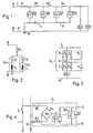
- Fig. 1 ein Prinzipschaltbild des Sicherheitskreises einer Aufzugsteuerung mit einer erfindungsgemäßen Überwachungsschaltung;
- Fig. 2 ein Ersatzschaltbild zur Erläuterung der Dimensionierung der erfindungsgemäß vorgesehenen Kontrollschaltungen;
- Fig. 3 ein weiteres Prinzipschaltbiid der erfindungsgemäßen Überwachungsschaltung zur Erläuterung des ungünstigsten Falles einer Störung und
- Fig. 4 ein schematisches Schaltbild einer bevorzugten Ausführungsform einer Kontrollschaltung der Überwachungsschaltung gemäß der Erfindung.
- 1 shows a basic circuit diagram of the safety circuit of an elevator control with a monitoring circuit according to the invention;
- 2 shows an equivalent circuit diagram to explain the dimensioning of the control circuits provided according to the invention;
- 3 shows another basic circuit diagram of the monitoring circuit according to the invention to explain the worst case of a fault and
- Fig. 4 is a schematic diagram of a preferred embodiment of a control circuit of the monitoring circuit according to the invention.
Im einzelnen zeigt Fig. 1 eine Anzahl von Sicherheitskontakten S1 bis S4, die in Reihe geschaltet sind. Die Serienschaltung der Sicherheitskontakte S1 bis S4 liegt ihrerseits in Serie zu zwei zueinander parallel geschalteten Fahrschützen RA und RS. Die Serienschaltung der Sicherheitskontakte S1 bis S4 mit der Parallelschaltung der Fahrschütze RA, RS liegt zwischen den beiden Anschlüssen A und B einer Speisespannungsquelle bzw. einer Betriebsspannungsquelle, die üblicherweise durch ein Drehstromnetz gebildet wird, weshalb der mit dem Anschluß A verbundene Leiter als Phasenleiter L bezeichnet ist, während der mit dem Anschluß B verbundene Leiter als Null-Leiter N bezeichnet ist, für den gemäß Fig. 1 ein Erdungsanschluß E vorgesehen ist. Die Fahrschütze RA und RS, die beispielsweise der Aufwärtsfahrt und der schnellen Fahrt eines zugehörigen Aufzugs zugeordnet sind, können In der Schaltung gemäß Fig. 1 nur dann anziehen, wenn alle vier Sicherheitskontakte S1 bis S4 geschlossen sind. Andererseits müssen die Schütze abfallen, sobald einer der vier Sicherheitskontakte S1 bis S4 anspricht. Diese Bedingungen sind für den in Fig. 1 gezeigten Schaltzustand nicht erfüllt, da der Sicherheitskontakt S3 geöffnet ist. Die Tatsache, daß der Sicherheitskontakt S3, der beispielsweise ein Tür- oder ein Riegelkontakt sein kann, geöffnet ist, soll gemäß der Erfindung als Störung erkannt werden, wobei gleichzeitig auch der Kontakt S3 als nicht-geschlossener Kontakt identifiziert werden soll. Diesem Ziel dienen erfindungsgemäß vier Kontrollschaltungen K1 bis K4, von denen jede jeweils einem der Sicherheitskontakte S1 bis S4 zugeordnet ist. Die Kontrollschaltungen K1 bis K4 liegen jeweils zwischen der von dem Anschluß A abgewandten Seite des zugeordneten Sicherheitskontaktes S1 bis S4 und dem Anschluß B bzw dem Null-Leiter N, wobei gemäß Fig. 1 für die zweiten Anschlüsse der Kontrollschaltungen K1 bis K4 eine von dem Null-Leiter N abzweigende Leitung N' vorgesehen ist.1 shows a number of safety contacts S1 to S4 which are connected in series. The series connection of the safety contacts S1 to S4 is in turn connected to two RA and RS contactors connected in parallel. The series connection of the safety contacts S1 to S4 with the parallel connection of the contactors RA, RS is between the two connections A and B of a supply voltage source or an operating voltage source, which is usually formed by a three-phase network, which is why the conductor connected to connection A is referred to as phase conductor L. is, while the conductor connected to the connection B is referred to as the neutral conductor N, for which, according to FIG. 1, an earth connection E is provided. The contactors RA and RS, which are assigned, for example, to the upward travel and the fast travel of an associated elevator, can only tighten in the circuit according to FIG. 1 if all four safety contacts S1 to S4 are closed. On the other hand, the contactors must drop out as soon as one of the four safety contacts S1 to S4 responds. These conditions are not met for the switching state shown in FIG. 1 since the safety contact S3 is open. The fact that the safety contact S3, which can be a door or a bolt contact, for example, is open, is to be recognized as a fault according to the invention, contact S3 also being to be identified as a non-closed contact. According to the invention, four control circuits K1 to K4 serve this purpose, each of which is assigned to one of the safety contacts S1 to S4. The control circuits K1 to K4 each lie between the side of the assigned safety contact S1 to S4 facing away from the connection A and the connection B or the neutral conductor N, wherein, according to FIG. 1, one of the zero for the second connections of the control circuits K1 to K4 Conductor N branching line N 'is provided.
Bei der Schaltung gemäß Fig. 1 können sich bei einer Unterbrechung U der Abzweigung N' auf dem Teilstück zwischen den zweiten Anschlüssen der Kontrollschaltungen K1 und K2 (sowie bei einer Unterbrechung zwischen dem Erdungsanschluß E und dem zweiten Anschluß der ersten Kontrollschaltung K1 beim Öffnen der Sicherheitskontaktes S3 dann Fehler ergeben, wenn über den in diesem Fall zur Verfügung stehenden Parallelzweig zur Sicherheitsstrecke ein Strom fließen könnte, der zu einem Ansprechen bzw. Nicht-Abfallen der Fahrschütze RA, RS führen könnte. Aus diesem Grunde müssen die Innenwiderstände R; der Kontrollschaltungen K1 bis K4 ausreichend hoch sein, um bei einer Unterbrechung U ein Anziehen der Fahrschütze RA, RS mit Sicherheit zu verhindern.1, there can be an interruption U of the branch N 'on the section between the second connections of the control circuits K1 and K2 (and an interruption between the ground connection E and the second connection of the first control circuit K1 when the safety contact is opened S3 then result in errors if a current could flow through the parallel branch available to the safety route in this case, which could cause the contactors RA, RS to respond or not to drop out. For this reason, the internal resistances R of the control circuits K1 up to K4 are high enough to reliably prevent the contactors RA, RS from being pulled in the event of an interruption U.
Fig. 2 zeigt ein Ersatzschaltbild der Schaltung gemäß Fig. 1 für den Fall elnes offenen Sicherheitskontaktes und einer Unterbrechung in der Abzweigung N'. Im einzelnen zeigt Fig. 2 zwischen den beiden Anschlüssen A und B einen Widerstand Rv, der in Serie zu der Parallelschaltung der Fahrschütze RA, RS liegt, die jeweils durch die Serienschaltung eines Ohm'schen Widerstandes R und einer Induktivität L angedeutet sind.FIG. 2 shows an equivalent circuit diagram of the circuit according to FIG. 1 for the case of an open safety contact and an interruption in the branch N '. 2 shows a resistance R v between the two connections A and B, which lies in series with the parallel connection of the contactors RA, RS, which are each indicated by the series connection of an ohmic resistor R and an inductance L.
Aus Fig. 3 der Zeichnung, wo anstelle der Parallelschaltung zweier Fahrschütze nur ein einziges Fahrschütz RA eingezeichnet ist, wird deutlich, daß für den allgemeinen Fall von n Sicherheitskontakten in der Sicherheitsstrecke und von n zugeordneten Kontrollschaltungen, die jeweils einen Innenwiderstand R; aufweisen, für den ungünstigsten Fall, nämlich bei einer Unterbrechung der Abzweigung N' zwischen dem Erdungsanschluß E und der ersten Kontrollschaltung K1 und bei einem offenen Sicherheitskontakt in der Mitte der Serienschaltung von Sicherheitskontakten für den Vorwiderstand folgender Wert erhalten wird:![]()
![]()
Für diesen Extremfall muß der Vorviderstand Ry immer noch hoch genug sein, um ein Anziehen der Fahrschütze bzw. - dies ist als Zusatzbedingung zu beachten - auch nur des einzigen in Fig. 3 gezeigten Fahrschützes RA zu verhindern bzw. das Abfallen zu gewährleisten. In der Praxis für den betrachteten, ungünstigsten Fall nur 10 % der Nennspannung zwischen den Anschlüssen A und B betragen darf, da gemäß der VDE-Vorschrift 0660 der Abfall der Schütze bei 10 % der Nennspannung gewährleistet sein muß, wobei von den Herstellerfirmen jedoch häufig höhere Werte von beispielsweise 15 % der Nennspannung garantiert werden.For this extreme case, the pre-resistance Ry must still be high enough to prevent the contactors from being tightened or - as an additional condition to be taken into account - only from the only contactor RA shown in FIG. 3 or to ensure that they fall off. In practice, in the worst-case scenario under consideration, only 10% of the nominal voltage between the connections A and B may be used, since according to VDE regulation 0660 the drop in contactors must be guaranteed at 10% of the nominal voltage, although often higher from the manufacturers Values of, for example, 15% of the nominal voltage are guaranteed.
Das erfindungsgemäße Konzept der Überwachung der einzelnen Sicherheitskontakte mit Hilfe von zugeordneten Kontrollschaltungen ist also unter Einhaltung aller Sicherheitsvorschriften dann zulässig, wenn gemäß den vorstehend erläuterten Überlegungen auch im ungünstigsten Fall eine entsprechende Höhe des Vorwiderstandes Ry bzw. des verbleibenden Widerstandswertes der Serienschaltung von Sicherheitskontakten mit den durch die zugeordneten Kontrollschaltungen gebildeten Parallelzweigen sichergestellt wird. In der Praxis läßt sich diese Forderung ohne besondere Schwierigkeiten realisieren.The concept according to the invention of monitoring the individual safety contacts with the aid of assigned control circuits is therefore permissible in compliance with all safety regulations if, in accordance with the considerations explained above, even in the worst case, a corresponding level of the series resistor Ry or the remaining resistance value of the series connection of safety contacts with the through the associated control circuits formed parallel branches is ensured. In practice, this requirement can be met without particular difficulty.
Fig. 4 zeigt ein schematisches Schaltbild einer in der Praxis für eine erfindungsgemäße Überwachungsschaltung eingesetzten Kontrollschaltung Ki. Man erkennt, daß die Kontrollschaltung K; eine Brückenschaltung Br umfasst, deren eine Brückendiagonale über Ohm'sche Widerstände R1, R2 an die Leitungen L bzw. N angeschlossen ist und deren ausgangsseitige Brückendiagonale mit der Eingangsseite (Fotodiode) eines Optokopplers 0 verbunden ist, dessen Ausgangsseite (Fototransistor) mit einer Schwellwertschaltung SW verbunden ist, deren Signalausgang SA signalisiert, ob der der Kontrollschaltung K; zugeordnete Sicherheitskontakt Si geöffnet oder geschlossen ist. Dabei werden der Fototransistor des Optokopplers 0 und die Schwellwertschaltung SW mit einer Hilfs-Gleichspannung + U gespeist, die beispielsweise mittels einer (nicht dargestellten) Gleichrichterschaltung aus der Ausgangsspannung eines mit der Betriebsspannung gespeisten Hilfstransformators gewonnen werden kann. Die beschriebene Uberwachungsschaltung mit Gleichrichterbrücke, Optokoppler und Schwellwert- bzw. Triggerschaltung bietet den besonderen Vorteil der galvanischen Trennung zwischen Schaltungseingang und -ausgang.FIG. 4 shows a schematic circuit diagram of a control circuit K i used in practice for a monitoring circuit according to the invention. It can be seen that the control circuit K; comprises a bridge circuit B r , the one bridge diagonal of which is connected to the lines L and N via ohmic resistors R1, R2 and the output-side bridge diagonal of which is connected to the input side (photodiode) of an optocoupler 0, the output side (phototransistor) of which is connected to a threshold circuit SW is connected, the signal output SA signals whether the control circuit K; assigned safety contact S i is open or closed. The phototransistor of the optocoupler 0 and the threshold circuit SW are fed with an auxiliary direct voltage + U, which can be obtained, for example, by means of a rectifier circuit (not shown) from the output voltage of an auxiliary transformer fed with the operating voltage. The described monitoring circuit with rectifier bridge, optocoupler and threshold or trigger circuit offers the particular advantage of electrical isolation between the circuit input and output.
Aus der vorstehenden Beschreibung wird deutlich, daß die erfindungsgemäße Kontrollschaltung auch unter Worstcase-Bedingungen (Widerstandstoleranz, Spannungstoleranzen, Kurzschluß an den Halbleitern) ordnungsgemäß arbeitet.From the above description it is clear that the control circuit according to the invention also works properly under worst case conditions (resistance tolerance, voltage tolerances, short circuit on the semiconductors).
Ergänzend soll noch darauf hingewiesen werden, daß durch geeignete Dimensionierung der Kontrollschaltung bis zu fünfzig in Serie liegende Sicherheitskontakte überwacht werden können.In addition, it should be pointed out that up to fifty safety contacts in series can be monitored by suitable dimensioning of the control circuit.
Claims (3)
Priority Applications (1)
| Application Number | Priority Date | Filing Date | Title |
|---|---|---|---|
| AT84112557T ATE35471T1 (en) | 1983-11-30 | 1984-10-18 | MONITORING CIRCUIT FOR ELEVATOR SAFETY CONTACTS. |
Applications Claiming Priority (2)
| Application Number | Priority Date | Filing Date | Title |
|---|---|---|---|
| DE3343303 | 1983-11-30 | ||
| DE19833343303 DE3343303A1 (en) | 1983-11-30 | 1983-11-30 | MONITORING CIRCUIT FOR THE SAFETY CONTACTS OF ELEVATOR |
Publications (2)
| Publication Number | Publication Date |
|---|---|
| EP0149727A1 EP0149727A1 (en) | 1985-07-31 |
| EP0149727B1 true EP0149727B1 (en) | 1988-06-29 |
Family
ID=6215659
Family Applications (1)
| Application Number | Title | Priority Date | Filing Date |
|---|---|---|---|
| EP84112557A Expired EP0149727B1 (en) | 1983-11-30 | 1984-10-18 | Supervisory circuit for the safety contacts of elevators |
Country Status (3)
| Country | Link |
|---|---|
| EP (1) | EP0149727B1 (en) |
| AT (1) | ATE35471T1 (en) |
| DE (2) | DE3343303A1 (en) |
Cited By (2)
| Publication number | Priority date | Publication date | Assignee | Title |
|---|---|---|---|---|
| CN104816996A (en) * | 2015-05-07 | 2015-08-05 | 广州永日电梯有限公司 | Detecting method of short circuit of door lock loop of elevator landing door |
| RU2798110C1 (en) * | 2020-10-16 | 2023-06-15 | Сучжоу Инованс Технолоджи Ко., Лтд. | Safety loop voltage control diagram |
Families Citing this family (12)
| Publication number | Priority date | Publication date | Assignee | Title |
|---|---|---|---|---|
| US5321216A (en) * | 1991-04-09 | 1994-06-14 | Otis Elevator Company | Restraining elevator car motion while the doors are open |
| FR2777087B1 (en) * | 1998-04-03 | 2000-05-05 | Otis Elevator Co | DEVICE FOR LOCATING A LOCKING DOOR CLOSING FAILURE IN AN ELEVATOR INSTALLATION |
| DE19849238C1 (en) * | 1998-10-26 | 2000-03-09 | O & K Rolltreppen Gmbh | Safety cut-out method for escalator or moving walkway has safety fault signals provided by safety chain combined with drive monitoring signals for operation of drive cut-out contacts |
| FI117797B (en) | 2005-04-08 | 2007-02-28 | Kone Corp | Elevator system |
| WO2006108433A1 (en) * | 2005-04-11 | 2006-10-19 | Otis Elevator Company | Safety circuit for a passenger conveyor system |
| AT502582B1 (en) * | 2005-09-20 | 2008-05-15 | Tuev Oesterreich Tech Ueberwac | MONITORING EQUIPMENT OF AN ELEVATOR |
| FI120088B (en) * | 2007-03-01 | 2009-06-30 | Kone Corp | Arrangement and method of monitoring the security circuit |
| MY166790A (en) * | 2009-10-26 | 2018-07-23 | Inventio Ag | Safety circuit in an elevator system |
| CN103809503A (en) * | 2014-03-04 | 2014-05-21 | 北京七星华创电子股份有限公司 | Safety door interlocking system of semiconductor equipment |
| EP3292064A1 (en) * | 2015-05-05 | 2018-03-14 | Inventio AG | Lift monitoring unit having a galvanically decoupled signal transmission |
| EP3305703A1 (en) | 2016-10-04 | 2018-04-11 | KONE Corporation | Elevator brake controller |
| CN112327984B (en) * | 2020-10-16 | 2022-04-19 | 苏州汇川技术有限公司 | Safety loop voltage regulating circuit |
Family Cites Families (5)
| Publication number | Priority date | Publication date | Assignee | Title |
|---|---|---|---|---|
| DE1068873B (en) * | 1959-11-12 | |||
| US2614160A (en) * | 1951-07-28 | 1952-10-14 | Gen Electric | Indicating system |
| DE2611145A1 (en) * | 1976-03-17 | 1977-09-22 | Grothe & Soehne Kg A | Vibration operated burglar alarm - protects many separated objects by monitoring current through line connecting vibration prone contacts |
| GB2073434B (en) * | 1980-03-28 | 1984-03-14 | Plessey Co Ltd | Remote switch monitoring circuit for mining |
| GB2110388A (en) * | 1981-10-30 | 1983-06-15 | Yorkshire Chemicals Ltd | Improvements relating to electrical controls for lifts, hoists and the like |
-
1983
- 1983-11-30 DE DE19833343303 patent/DE3343303A1/en not_active Withdrawn
-
1984
- 1984-10-18 AT AT84112557T patent/ATE35471T1/en not_active IP Right Cessation
- 1984-10-18 DE DE8484112557T patent/DE3472481D1/en not_active Expired
- 1984-10-18 EP EP84112557A patent/EP0149727B1/en not_active Expired
Cited By (2)
| Publication number | Priority date | Publication date | Assignee | Title |
|---|---|---|---|---|
| CN104816996A (en) * | 2015-05-07 | 2015-08-05 | 广州永日电梯有限公司 | Detecting method of short circuit of door lock loop of elevator landing door |
| RU2798110C1 (en) * | 2020-10-16 | 2023-06-15 | Сучжоу Инованс Технолоджи Ко., Лтд. | Safety loop voltage control diagram |
Also Published As
| Publication number | Publication date |
|---|---|
| DE3472481D1 (en) | 1988-08-04 |
| ATE35471T1 (en) | 1988-07-15 |
| DE3343303A1 (en) | 1985-08-08 |
| EP0149727A1 (en) | 1985-07-31 |
Similar Documents
| Publication | Publication Date | Title |
|---|---|---|
| DE102005055325B3 (en) | Safety switching device for use in automated operation system, has switching arrangement determining operating voltage at connecting terminals, where arrangement is arranged to control output switching signal depending on operating voltage | |
| EP0149727B1 (en) | Supervisory circuit for the safety contacts of elevators | |
| DE4041672A1 (en) | Monitoring unit for DC circuit for photovoltaic prodn. plants - which with line interference occuring within monitored stretch, current flow through monitored line section is interrupted using two monitoring lines | |
| EP0884821A1 (en) | Arrangement for power distribution, in particular for an aircraft | |
| DE102016101075B4 (en) | Motor drive having a function to detect a failure in a dynamic braking circuit | |
| DE2025743A1 (en) | Method and device for uninterrupted switching of at least one AC power consumer from one voltage source or current source to another voltage source or current source | |
| DE3044203A1 (en) | AUTOMATIC SHUTDOWN SYSTEM | |
| DE2711416C2 (en) | Arrangement for displaying the switching status of the switches | |
| DE3039575A1 (en) | FEEDING DEVICE FOR A CONSUMER LOCATED IN A REMOTE-DELIVERED NEWS TRANSMISSION ROUTE | |
| DE4325663A1 (en) | Power switch relay circuit | |
| DE2933439C2 (en) | Procedure for the commissioning of the bilateral remote feeding of intermediate points of a device of the communication technology | |
| DE4430441C2 (en) | Device for controlling electrical consumers | |
| DE2108020A1 (en) | Control circuit to prevent a load from being switched on again if the load resistance is too low | |
| DE19606894A1 (en) | Electronic circuit stage for safe control and monitoring of electrical loads in railway applications | |
| EP0165464B1 (en) | Circuit arrangement for operating a light signal in a railway system | |
| DE19808595B4 (en) | Arrangement with an electrical load in series with two controllable semiconductor devices | |
| DE19606896C2 (en) | Circuit for setting and monitoring light signals | |
| EP0678889A1 (en) | Contactor safety combination | |
| DE3029851A1 (en) | CIRCUIT ARRANGEMENT FOR THE SIGNAL TECHNOLOGY SAFE CONTROL OF A POWER CONSUMER | |
| DE3314233C2 (en) | ||
| EP0503122B1 (en) | Arrangement for commuting primary leads during faults | |
| EP0030004A1 (en) | Circuit arrangement for the remote supply of intermediate posts in a telecommunication contrivance by means of direct current series supply | |
| DE3330869A1 (en) | Circuit for detecting shorts to earth in the feed circuits of rotary current drives for sets of points | |
| DE469386C (en) | Circuit for automatic route blocking | |
| DE2808618B1 (en) | Monitoring circuit for power supply devices |
Legal Events
| Date | Code | Title | Description |
|---|---|---|---|
| PUAI | Public reference made under article 153(3) epc to a published international application that has entered the european phase |
Free format text: ORIGINAL CODE: 0009012 |
|
| AK | Designated contracting states |
Designated state(s): AT BE CH DE FR GB LI NL |
|
| 17P | Request for examination filed |
Effective date: 19851026 |
|
| 17Q | First examination report despatched |
Effective date: 19870128 |
|
| GRAA | (expected) grant |
Free format text: ORIGINAL CODE: 0009210 |
|
| AK | Designated contracting states |
Kind code of ref document: B1 Designated state(s): AT BE CH DE FR GB LI NL |
|
| REF | Corresponds to: |
Ref document number: 35471 Country of ref document: AT Date of ref document: 19880715 Kind code of ref document: T |
|
| REF | Corresponds to: |
Ref document number: 3472481 Country of ref document: DE Date of ref document: 19880804 |
|
| GBT | Gb: translation of ep patent filed (gb section 77(6)(a)/1977) | ||
| ET | Fr: translation filed | ||
| PLBE | No opposition filed within time limit |
Free format text: ORIGINAL CODE: 0009261 |
|
| STAA | Information on the status of an ep patent application or granted ep patent |
Free format text: STATUS: NO OPPOSITION FILED WITHIN TIME LIMIT |
|
| 26N | No opposition filed | ||
| PGFP | Annual fee paid to national office [announced via postgrant information from national office to epo] |
Ref country code: BE Payment date: 19901019 Year of fee payment: 7 |
|
| PGFP | Annual fee paid to national office [announced via postgrant information from national office to epo] |
Ref country code: NL Payment date: 19901031 Year of fee payment: 7 |
|
| PG25 | Lapsed in a contracting state [announced via postgrant information from national office to epo] |
Ref country code: BE Effective date: 19911031 |
|
| BERE | Be: lapsed |
Owner name: THYSSEN-M.A.N. AUFZUGE G.M.B.H. Effective date: 19911031 |
|
| PG25 | Lapsed in a contracting state [announced via postgrant information from national office to epo] |
Ref country code: NL Effective date: 19920501 |
|
| NLV4 | Nl: lapsed or anulled due to non-payment of the annual fee | ||
| PGFP | Annual fee paid to national office [announced via postgrant information from national office to epo] |
Ref country code: CH Payment date: 19981027 Year of fee payment: 15 |
|
| PGFP | Annual fee paid to national office [announced via postgrant information from national office to epo] |
Ref country code: AT Payment date: 19981030 Year of fee payment: 15 |
|
| PG25 | Lapsed in a contracting state [announced via postgrant information from national office to epo] |
Ref country code: AT Free format text: LAPSE BECAUSE OF NON-PAYMENT OF DUE FEES Effective date: 19991018 |
|
| PG25 | Lapsed in a contracting state [announced via postgrant information from national office to epo] |
Ref country code: LI Free format text: LAPSE BECAUSE OF NON-PAYMENT OF DUE FEES Effective date: 19991031 Ref country code: CH Free format text: LAPSE BECAUSE OF NON-PAYMENT OF DUE FEES Effective date: 19991031 |
|
| REG | Reference to a national code |
Ref country code: CH Ref legal event code: PL |
|
| PGFP | Annual fee paid to national office [announced via postgrant information from national office to epo] |
Ref country code: FR Payment date: 20001013 Year of fee payment: 17 |
|
| PGFP | Annual fee paid to national office [announced via postgrant information from national office to epo] |
Ref country code: GB Payment date: 20001018 Year of fee payment: 17 |
|
| PGFP | Annual fee paid to national office [announced via postgrant information from national office to epo] |
Ref country code: DE Payment date: 20001201 Year of fee payment: 17 |
|
| PG25 | Lapsed in a contracting state [announced via postgrant information from national office to epo] |
Ref country code: GB Free format text: LAPSE BECAUSE OF NON-PAYMENT OF DUE FEES Effective date: 20011018 |
|
| REG | Reference to a national code |
Ref country code: GB Ref legal event code: IF02 |
|
| GBPC | Gb: european patent ceased through non-payment of renewal fee |
Effective date: 20011018 |
|
| PG25 | Lapsed in a contracting state [announced via postgrant information from national office to epo] |
Ref country code: FR Free format text: LAPSE BECAUSE OF NON-PAYMENT OF DUE FEES Effective date: 20020628 |
|
| PG25 | Lapsed in a contracting state [announced via postgrant information from national office to epo] |
Ref country code: DE Free format text: LAPSE BECAUSE OF NON-PAYMENT OF DUE FEES Effective date: 20020702 |
|
| REG | Reference to a national code |
Ref country code: FR Ref legal event code: ST |