EP0252219A2 - Method of guiding an unmanned vehicle - Google Patents
Method of guiding an unmanned vehicle Download PDFInfo
- Publication number
- EP0252219A2 EP0252219A2 EP87104452A EP87104452A EP0252219A2 EP 0252219 A2 EP0252219 A2 EP 0252219A2 EP 87104452 A EP87104452 A EP 87104452A EP 87104452 A EP87104452 A EP 87104452A EP 0252219 A2 EP0252219 A2 EP 0252219A2
- Authority
- EP
- European Patent Office
- Prior art keywords
- vehicle
- ground
- movement
- passage
- guiding
- Prior art date
- Legal status (The legal status is an assumption and is not a legal conclusion. Google has not performed a legal analysis and makes no representation as to the accuracy of the status listed.)
- Granted
Links
- 238000000034 method Methods 0.000 title claims abstract description 46
- 238000001514 detection method Methods 0.000 claims description 14
- 230000004044 response Effects 0.000 claims description 7
- 239000011796 hollow space material Substances 0.000 claims description 5
- 238000012545 processing Methods 0.000 description 18
- 239000000463 material Substances 0.000 description 12
- 238000010586 diagram Methods 0.000 description 7
- 238000005259 measurement Methods 0.000 description 5
- 239000007769 metal material Substances 0.000 description 5
- 230000008569 process Effects 0.000 description 5
- NAWXUBYGYWOOIX-SFHVURJKSA-N (2s)-2-[[4-[2-(2,4-diaminoquinazolin-6-yl)ethyl]benzoyl]amino]-4-methylidenepentanedioic acid Chemical compound C1=CC2=NC(N)=NC(N)=C2C=C1CCC1=CC=C(C(=O)N[C@@H](CC(=C)C(O)=O)C(O)=O)C=C1 NAWXUBYGYWOOIX-SFHVURJKSA-N 0.000 description 3
- 230000006870 function Effects 0.000 description 3
- 238000005070 sampling Methods 0.000 description 3
- 230000003111 delayed effect Effects 0.000 description 2
- 230000000694 effects Effects 0.000 description 2
- 229920001971 elastomer Polymers 0.000 description 2
- 239000000835 fiber Substances 0.000 description 2
- 230000006698 induction Effects 0.000 description 2
- 230000007257 malfunction Effects 0.000 description 2
- 229910052751 metal Inorganic materials 0.000 description 2
- 239000002184 metal Substances 0.000 description 2
- 230000001960 triggered effect Effects 0.000 description 2
- 229910000838 Al alloy Inorganic materials 0.000 description 1
- 235000009074 Phytolacca americana Nutrition 0.000 description 1
- 240000007643 Phytolacca americana Species 0.000 description 1
- 241000270295 Serpentes Species 0.000 description 1
- 230000001133 acceleration Effects 0.000 description 1
- 230000002411 adverse Effects 0.000 description 1
- 229910052782 aluminium Inorganic materials 0.000 description 1
- XAGFODPZIPBFFR-UHFFFAOYSA-N aluminium Chemical compound [Al] XAGFODPZIPBFFR-UHFFFAOYSA-N 0.000 description 1
- 239000010426 asphalt Substances 0.000 description 1
- 238000004891 communication Methods 0.000 description 1
- 238000007796 conventional method Methods 0.000 description 1
- 238000012937 correction Methods 0.000 description 1
- 230000007423 decrease Effects 0.000 description 1
- 238000006073 displacement reaction Methods 0.000 description 1
- 230000005672 electromagnetic field Effects 0.000 description 1
- 238000002474 experimental method Methods 0.000 description 1
- 229910052745 lead Inorganic materials 0.000 description 1
- 230000005389 magnetism Effects 0.000 description 1
- 230000007246 mechanism Effects 0.000 description 1
- 238000012986 modification Methods 0.000 description 1
- 230000004048 modification Effects 0.000 description 1
- 239000012811 non-conductive material Substances 0.000 description 1
- 230000035699 permeability Effects 0.000 description 1
- 229920006395 saturated elastomer Polymers 0.000 description 1
- 238000004092 self-diagnosis Methods 0.000 description 1
- 239000010935 stainless steel Substances 0.000 description 1
- 229910001220 stainless steel Inorganic materials 0.000 description 1
- 239000000126 substance Substances 0.000 description 1
- MLGCXEBRWGEOQX-UHFFFAOYSA-N tetradifon Chemical compound C1=CC(Cl)=CC=C1S(=O)(=O)C1=CC(Cl)=C(Cl)C=C1Cl MLGCXEBRWGEOQX-UHFFFAOYSA-N 0.000 description 1
- 230000000007 visual effect Effects 0.000 description 1
- 229910000859 α-Fe Inorganic materials 0.000 description 1
Images


Classifications
-
- G—PHYSICS
- G05—CONTROLLING; REGULATING
- G05D—SYSTEMS FOR CONTROLLING OR REGULATING NON-ELECTRIC VARIABLES
- G05D1/00—Control of position, course or altitude of land, water, air, or space vehicles, e.g. automatic pilot
- G05D1/02—Control of position or course in two dimensions
- G05D1/021—Control of position or course in two dimensions specially adapted to land vehicles
- G05D1/0276—Control of position or course in two dimensions specially adapted to land vehicles using signals provided by a source external to the vehicle
- G05D1/028—Control of position or course in two dimensions specially adapted to land vehicles using signals provided by a source external to the vehicle using a RF signal
- G05D1/0282—Control of position or course in two dimensions specially adapted to land vehicles using signals provided by a source external to the vehicle using a RF signal generated in a local control room
-
- G—PHYSICS
- G05—CONTROLLING; REGULATING
- G05D—SYSTEMS FOR CONTROLLING OR REGULATING NON-ELECTRIC VARIABLES
- G05D1/00—Control of position, course or altitude of land, water, air, or space vehicles, e.g. automatic pilot
- G05D1/02—Control of position or course in two dimensions
- G05D1/021—Control of position or course in two dimensions specially adapted to land vehicles
- G05D1/0231—Control of position or course in two dimensions specially adapted to land vehicles using optical position detecting means
- G05D1/0246—Control of position or course in two dimensions specially adapted to land vehicles using optical position detecting means using a video camera in combination with image processing means
-
- G—PHYSICS
- G05—CONTROLLING; REGULATING
- G05D—SYSTEMS FOR CONTROLLING OR REGULATING NON-ELECTRIC VARIABLES
- G05D1/00—Control of position, course or altitude of land, water, air, or space vehicles, e.g. automatic pilot
- G05D1/02—Control of position or course in two dimensions
- G05D1/021—Control of position or course in two dimensions specially adapted to land vehicles
- G05D1/0259—Control of position or course in two dimensions specially adapted to land vehicles using magnetic or electromagnetic means
- G05D1/0261—Control of position or course in two dimensions specially adapted to land vehicles using magnetic or electromagnetic means using magnetic plots
-
- G—PHYSICS
- G05—CONTROLLING; REGULATING
- G05D—SYSTEMS FOR CONTROLLING OR REGULATING NON-ELECTRIC VARIABLES
- G05D1/00—Control of position, course or altitude of land, water, air, or space vehicles, e.g. automatic pilot
- G05D1/02—Control of position or course in two dimensions
- G05D1/021—Control of position or course in two dimensions specially adapted to land vehicles
- G05D1/0259—Control of position or course in two dimensions specially adapted to land vehicles using magnetic or electromagnetic means
- G05D1/0265—Control of position or course in two dimensions specially adapted to land vehicles using magnetic or electromagnetic means using buried wires
-
- G—PHYSICS
- G05—CONTROLLING; REGULATING
- G05D—SYSTEMS FOR CONTROLLING OR REGULATING NON-ELECTRIC VARIABLES
- G05D1/00—Control of position, course or altitude of land, water, air, or space vehicles, e.g. automatic pilot
- G05D1/02—Control of position or course in two dimensions
- G05D1/021—Control of position or course in two dimensions specially adapted to land vehicles
- G05D1/0268—Control of position or course in two dimensions specially adapted to land vehicles using internal positioning means
- G05D1/0272—Control of position or course in two dimensions specially adapted to land vehicles using internal positioning means comprising means for registering the travel distance, e.g. revolutions of wheels
-
- G—PHYSICS
- G05—CONTROLLING; REGULATING
- G05D—SYSTEMS FOR CONTROLLING OR REGULATING NON-ELECTRIC VARIABLES
- G05D1/00—Control of position, course or altitude of land, water, air, or space vehicles, e.g. automatic pilot
- G05D1/02—Control of position or course in two dimensions
- G05D1/021—Control of position or course in two dimensions specially adapted to land vehicles
- G05D1/0259—Control of position or course in two dimensions specially adapted to land vehicles using magnetic or electromagnetic means
- G05D1/0263—Control of position or course in two dimensions specially adapted to land vehicles using magnetic or electromagnetic means using magnetic strips
-
- G—PHYSICS
- G05—CONTROLLING; REGULATING
- G05D—SYSTEMS FOR CONTROLLING OR REGULATING NON-ELECTRIC VARIABLES
- G05D1/00—Control of position, course or altitude of land, water, air, or space vehicles, e.g. automatic pilot
- G05D1/02—Control of position or course in two dimensions
- G05D1/021—Control of position or course in two dimensions specially adapted to land vehicles
- G05D1/0268—Control of position or course in two dimensions specially adapted to land vehicles using internal positioning means
- G05D1/027—Control of position or course in two dimensions specially adapted to land vehicles using internal positioning means comprising intertial navigation means, e.g. azimuth detector
Definitions
- the present invention relates to a method of guiding an unmanned vehicle.
- Japanese Patent Application No. 93406/1982 discloses a technical concept that a plurality of ground marks are placed at proper positions on the moving passage and the correct position of the vehicle can be measured by detecting them on the vehicle side is disclosed.
- a so-called navigational guiding method for guiding a vehicle along a previously taught moving passage has been hitherto employed in aircraft or ship.
- direction detecting means and movement distance detecting means are used to estimate the current position of an unmanned vehicle, but error in estimated value of position is increasingly accumulated due to slippage of the vehicle, ruggedness of ground or the like factor. Accordingly, the current correct position of the vehicle is obtained and the estimated value is then corrected with reference to the current correct position.
- controlling is effected for orienting the fore wheels as seen in the direction of movement toward the target point.
- the navigational guiding process fails to function properly.
- An object of the present invention is to provide a method of guiding an unmanned vehicle which assures that the method can be practiced with the use of inexpensive ground mark detecting means.
- Another object of the present invention is to provide a method of guiding an unmanned vehicle which assures that teaching of a moving passage is effected very simply and moreover changing of the moving passage is carried out easily.
- Still another object of the present invention is to provide a method of guiding an unmanned vehicle which assures that the vehicle moves on a moving passage having complicated curved portions without any occurrence of delayed steering.
- Another object of the present invention is to provide a method of guiding an unmanned vehicle which assures that guiding of the vehicle is effected with a proper steering angle in the case where rear wheels as seen in the direction of movement of the vehicle serves as steering wheel.
- a certain number of ground marks each of which comprises a plurality of line segments are placed on a moving passage of an unmanned vehicle and a relative positional relation between the ground mark and the vehicle is obtained by measuring amount of movement of the vehicle between the adjacent line segments when the vehicle moves across the ground mark.
- ground marks are placed at a plurality of predetermined positions within the moving area of the vehicle and a moving passage of the vehicle is determined by selectively assigning the ground marks. Further, by interpolating an area between the adjacent assigned ground marks, the position of each of ground points on the moving passage is obtained and the thus obtained position is then taught to the vehicle.
- a distance between the current position of a target ground point on the moving passage and the current position of the vehicle is obtained during navigational guiding and when the distance becomes shorter than a predetermined one or it increases as the vehicle goes on, the current target ground point is changed to next one.
- an imaginary steering wheel is supposed at the position located forwardly of a non-steering wheel by a length of the wheel base of the vehicle in the case where the rear wheel as seen in the direction of movement of the vehicle serves as steering wheel.
- a steering angle is then obtained when the imaginary steering wheel is oriented toward the current target ground point on the moving passage and a value of the steering angle of which sign is reversed is used as a steering command value.
- reference numeral 1 designates an unmanned vehicle on which no operator rides
- reference numeral 2 does a ground mark
- reference numeral 3 does a track on which it is planned that the unmanned vehicle 1 moves
- reference numeral 4 does a locus along which the unmanned vehicle 1 has moved actually
- reference numeral 5 does a sensor which is mounted on .the unmanned vehicle 1.
- the unmanned vehicle 1 is equipped with a direction detector and a running distance detector (both of which are not shown in the drawing) and automatic steering for alowing the vehicle 1 to move on the track 3 is carried out by estimating with the use of the above-mentioned detectors the current position where the vehicle is located at present.
- each of the ground marks 2 is constituted by three line segments 2a, 2b and 2c which extend across the passage 3 in the transverse direction.
- the line segments 2a and 2c are in parallel with one another and the line segment 2b diagonally extends between the tail end of the line segment 2a and the leading end of the line segment 2c.
- the line segments 2a and 2c extend at a right angle relative to the passage 3 and the passage 3 extends through the middle point of each of the line segments.
- Metallic plate, metallic tape, metallic wire or the like is employed as material constituting each of the line esgments on the assumption that floor is built by concrete without any piece of metallic material embedded therein.
- a metallic material sensor for instance, eddy current sensor is employable for the sensor 5 mounted on the vehicle to detect line segments.
- eddy current sensor is employable for the sensor 5 mounted on the vehicle to detect line segments.
- the locus 4 intersects the line segment 2a at point P 1 , then it does the line segments 2b at point P 2 and finally it does the line segment 2c at point P 3 .
- the sensor 5 generates signals which inform that the sensor 5 detects the line segments 2a, 2b and 2c at points P 1 , P 2 and P 3 (see Fig. 3).
- a ratio of distance L 1 between point P 1 and P 2 to distance L 2 between P 2 and P 3 is equal to a ratio of time interval T 1 to time interval T 2 in Fig. 3 and moreover it is equal to a ratio of length l 1 to length l 2 .
- an amount of course deviation l 3 of the vehicle from the center line on the ground mark 2 (which is identical to the passage 3) can be determined by receiving output signals from the sensor 5 and measuring time intervals T 1 and T 2 . This is because amount of the course deviation l 3 can be expressed as follows: where V is the width of the mark 2.
- the width of the ground mark that is, (l 1 +l 2 ) defines a scope of detection.
- the vehicle is equipped with two sensors 5 which are located in a spaced relation in the transverse direction it results that a scope of detection can be widened by a distance between the sensors.
- the senor 5 may sense the ground mark 2 incorrectly when certain article made of metallic material is placed on the floor. Similarly, in the case where white lines are employed for the line segments 2a to 2c, incorrect sensing may be effected when the floor has a spot which is coated with white ink.
- one or more additional line segments are provided at the position located before or after the ground mark 2.
- Fig. 4 illustrates the case where new line segments 2d and 2e are added to the ground mark 2 which comprises lines segments 2a, 2b and 2c. As is apparent from the drawing, the line segments 2d and 2e extend in parallel with the line segments 2a and 2c. In this case five sensor outputs indicative of movement of the sensor 5 on the locus 4 are as shown in Fig. 5.
- ratio of time interval T 3 to time interval T 4 or T 5 relative to output signals from the sensor does not vary irrespective of how the vehicle is deviated from the correct course but ratio of time interval T 1 to time interval T 2 varies in dependence on an amount of deviation of the vchicle from the course. Namely, sensor signals appear at time intervals T 41 T 5 and T 3t as long as any signal outputted from the sensor 5 does not contain noise. Accordingly, it can be discriminated with reference to ratios relative to time intervals as mentioned above whether or not a detection signal from the sensor is generated by line segment or noise.
- a shape of the ground mark 2 should not be limited only to that as shown in Fig. 2.
- a ground mark 2' including line segments 2'a, 2'b and 2'c of which both the sides are cut off as shown in Fig. 6 may be employable.
- ground marks whose shape is reversed to those shown in Figs. 2 and 6 may be employable also.
- the ground mark 2 by locating the ground mark 2 at a known position on the track 3, it is possible to detect the current correct position of the vehicle when the latter moves past the ground mark 2. Since the current correct position can be sensed in that way, the existent position which is estimated continuously on the vehicle side can be corrected to the above-mentioned current correct position at every time when the ground mark is detected.
- an entrance angle of the vehicle into the ground mark can be obtained by measuring a period of time required for moving by the aforesaid distance.
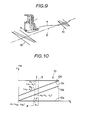
- Fig. 7 shows an embodiment in which two ground marks 6 each of which is constructed by two line segments 6a and 6b as shown in Fig. 8 are placed on the moving track in the spaced relation and an unattained vehicle 1 is equipped with two sensors 5 and 5' to guide movement thereof.
- both the line segments 6a and 6b are not in parallel with one another. In this embodiment they are so arranged that the line segment 6a extends at a right angle relative to the planned moving track 3 and the line segment 6b intersects the lino segment 6a at the one end (intersection 0) of the line segment 6a at an inclination angle of ⁇ .
- the locus 7 first intersects the line segment 6a at point P 11 located on the line segment 6a and then it intersects the line segment 6b at point P 12 located on the line segment 6b.
- the locus 8 first intersects the line segment 6a at point P 11 ' located on the line segment 6a and then it intersects the line segment 6b at point P 12 ' located on the line setment 6b. Accordingly, there are generated signals which inform that the sensor 5 detects the line segments by intersections P 11 and P 12 and the sensor 5' detects the line segments by intersections P 11 ' and P 12 '.
- the point P 0 represents the position where the sensor 5 is located when the sensor 5' reaches the point P 11 '. Since a triangle P 11 , P 11 ', P 0 defined by intersections P 11 and P 11 ' and position P 0 is a right-angled triangle, an angle of 0 is represented by the following formula (1). where L designates a distance between both the sensors 5 and 5'.
- the aforesaid angle e can be obtained in accordance with the formula (1) by measuring the distance P 0 P 11 of movement of the vehicle 1 from the time when the sensor 5' reaches the intersection P 11 ' to the time when the sensor 5 reaches the intersection P 11 , wherein measurement is achieved by using means, for instance, length measuring ring or the like.
- Distance OP 11 between the intersection O (reference point) of the line segments 6a and 6b and the interesection P 11 as well as distance OP 11 ' between the intersection O and the intersection P 11 ' are represented by the following formulas (2). where ⁇ designates an angle formed by the line segments 6a and 6b.
- the position of the sensors 5 and 5' as seen in the transverse direction relative to the line segment 6a can be obtained with reference to the aforesaid distances, angle 8 and angle
- the amount of course deviation obtained in the above-described manner is typically utilized as an information for controlling steering of the vehicle so as to cancel this amount of course deviation. Further, it may be utilized for correcting the estimated position of the vehicle when navigational guidance to be described later is carried out. Namely, since a true coordinate position of the vehicle can be detected with reference to the coordinate position where ground marks 2 or 6 is placed and the aforesaid amount of course deviation, the existent position which is estimated on the vehicle side during navigational guiding can be corrected with reference to the above-mentioned true coordinate position.
- both the position of the vehicle 1 and the direction of movement of the same can be detected with the use of a single sensor 5.
- each of the ground marks 10 is constituted by two line segments 10a and 10d which are in parallel with one another and other two line segments 10b and 10c which are interposed between the two line segments 10a and 10d in such a manner as not to be in parallel with them.
- the line segments 10a and 10d extend at a right angle relative to the planned moving passage 3 or the vehicle 1 and the line segments 10b and 10c at least intersect the planned moving passage 3.
- the locus 4 first intersects the line segment 10a at point m 1 and then it intersects the line segment 10b at point m 2 . Further, it intersects the line segment 10c at point m 3 and finally it intersects the line segment 10d at point m 4 .
- Coordinates (x 2 , y 2 ) of the intersection m 2 and coordinates (x 3 , y 3 ) of the intersection m 3 can be obtained by measuring four distances between the intersections, that is, m 1 m 2 , m 2 m 4 , m 1 m 3 and m 3 m 4 .
- V designates width of the ground mark 2 as seen in the x-direction, while Y does a distance between line segments as seen in the y-direction.
- coordinates (x 2 , y 2 ) of the intersection m 2 and coordinates (x 3 , y 3 ) in the x-y coordinate system in Fig. 10 can be obtained in compliance with the above-mentioned step of obtaining coordinate (x 1 , x 2 ) of point P 2 with the use of distances between the intersections m 1 m 2 , m 2 m 4 and m 1 m 3 , m 3 m 4 .
- coordinates (x 4 , y 4 ) of the intersection m 4 are determined in accordance with the following formulas.
- an angle of ⁇ 1 can be obtained in accordance with the formula (6). Further after the angle of ⁇ 1 is obtained in this way, the position where the vehicle 1 is located can be obtained in accordance with the formula (7).
- line segments 10b and 10c are not necessarily parallel with each other. z 0 (x z0 , y z0 ) of the ground mark 2 and the position T where the sensors intersects the line segment 2b can be represented in accordance with the following formula (8).
- an angle of 8 3 formed by the angle ⁇ z0 indicative of the direction of extension of the ground mark 2 and the angle ⁇ indicative of the direction of movement of the vehicle 1 can be represented in accordance with the following formula (9).
- coordinates of the reference position z 0 (x z0 , y z0 ) can be represented in accordance with the following formulas (11).
- the angle ⁇ indicative of the direction of the vehicle 1 can be obtained from the formula (10) with reference to the above-noted ⁇ l and the angle ⁇ z0 indicative of the direction of extension of the ground mark 2. Further, when the coordinates (x z0 , y z0 ) of the reference position of the ground mark 2 and the angle ⁇ z0 indicative of the direction of extension of the ground mark 2 are given and the distance e is measured with the use of length measuring means, the coordinates (x t , y t ) of the position T, that is, coordinates representative of the position where the vehicle 1 is located are obtainable from the formula (11).
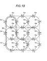
- a plurality of ground marks Z12 to Z 76 are previously arranged within a moving area for the unmanned vehicle 1. It should be noted that each of the ground marks as mentioned above is placed at the predetermined position while extending in the predetermined direction.
- Fig. 14 schematically illustrates one example of an apparatus for carrying out the method of teaching a moving passage for an attended vehicle as well as the method of guiding movement of the same.
- the position of all ground marks Z 12 to Z 76 and the direction of extension of the same are stored in an all ground mark coordinate memory 30.
- a passage setting device 31 is manually operated when a moving passage is determined, and a required moving passage is determined by successively selecting and assigning the ground marks Z 12 to Z 76 . For instance, in the case where a moving passage as represented by a real line 50 in Fig.
- ground mark Z 21 serves as starting point and terminating point.
- a passage teaching computor 32 successively reads from the all mark coordinate memory 30 positional coordinates and direction for each of the ground marks assigned by the passage setting device 31 and thereby obtains positional coordinates of each ground point between the adjacent ground marks by linear or arch interpolation. Then, data indicative of positional coordinates and direction relative to each of the ground marks as well as data indicative of positional coordinates relative to each of ground points obtained by interpolation in that way are transmitted via a transmitter 33.
- Step 100 data indicative of its coordinates (x z1 , y z1 ) and data indicative of direction ⁇ z1 are transmitted from the transmitter 33 (Step 101).
- Step 101 data indicative of coordinates (x zi , y zi ) and direction ( ⁇ zi ) relative to the assigned ground mark Z i are inputted (step 103).
- Step 104 the program goes to Step 105 (Step 104).
- Step 105 comparison is made between direction ⁇ zi of the ground mark which has been inputted at this time and direction ⁇ zi-1 of the ground mark which was inputted at the preceding time.
- Step 106 the program goes to Step 106. If not, the program goes to Step 107.
- a linear line extending between ground marks z i and Z i-1 is interpolated by series of ground points, while at Step 107 both the ground marks z i and z i-1 are connected to one another by an assigned arch and then interpolated by a series of ground points.
- Z i ground marks Z i and Z i-1 are ground marks Z 61 and Z 41 in Fi g. 13
- the intermediate area between both the ground marks is interpolated by a series of ground points and positional coordinates relative to each ground point among the series of ground points are objtained at Step 106.
- ground marks Z i and Z i-1 are ground marks Z 72 and Z 61 in Fi g. 13
- the intermediate area between both the ground marks is interporated with tespect to an arch by a series of ground points and positional coordinates relative to each ground point on the thus interpolated arch are obtained at Step 107.
- Coordinate data indicative of position of each ground point among the series of ground points between the ground marks Z i and Z i-1 as obtained by interpolation, coordinate data (x zi , y zi ) indicative of position of the ground mark Z 3 and data indicative of direction ⁇ z of the same are transmitted from the transmitter 33 at Step 108.
- Step 109 After i has an increment by 1 at Step 109, the step is caused to return to Step 103.
- an assigned moving passage is the moving passage 50 as shown in Fig. 15
- data indicative of positional coordinates and direc- tion of the ground marks Z 21 , Z 41 , Z 61 --- Z 12 , Z 21 and data indicative of positional coordinate of each ground point between the adjacent ground marks are transmitted from the transmitter 33.
- the above-mentioned data transmitted from the transmitter 33 are received by a receiver 40 mounted on the vehicle 1.
- Data indicative of coordinates and direction of each of the ground marks on the moving passage are successively stored in a mark coordinate memory 41, while coordinate data indicative of position of each ground point between the adjacent ground marks are successively stored in a passage memory 42.
- a direction detector 43 is constructed in the form of a rate gyroscope which is adapted to detect direction of movement of the vehicle 1 by detecting an amount of displacement (angular speed) in the direction of movement of the vehicle 1 and integrating it.
- a running distance detector 44 detects a distance of movement of the vehicle 1 which moves momently by using the number of revolutions of wheels or the like.
- a mark detector 45 detects existence of line segments constituting the ground mark when the vehicle 1 moves across the ground mark. Incidentally, this detector 45 corresponds to two sensors 5 and 5' in Fig. 11.
- a estimated vehicle position processing circuit 46 is effective for estimating the current position of the vehicle 1 in response to signals indicative of direction and running distance of the vehicle 1 which are momently outputted from a direction detector 43 and a running distance detector 44 and outputs a signal indicative of the estimated position of the vehicle 1.
- a vehicle position processing circuit 47 obtains the position of the vehicle 1 relative to the ground mark with reference to each of output signals from the running distance detector 44 and a mark detector 45 and moreover specifically designates the ground mark detected by the ground mark detector 45 with reference to signals outputted from the estimated position processing circuit 46 to indicate an estimated position of the vehicle 1. Then, data indicative of positional coordinates and direction of extension of the specifically designated ground mark are read from a memory 41 and the current correct position of the vehicle 1 in a x-y coordinate system representative of the passage thereof is obtained from the thus read data with reference to the position of the vehicle 1 relative to the ground mark. Thereafter, the estimated position obtained with the aid of the vehicle estimated position processing circuit 46 is corrected to the above-mentioned correct position. It should be noted that this position correction is carried out at every time when the vehicle moves past the ground mark.
- a steering command processing circuit 48 successively reads coordinate data relative to a series . of ground points on the passage stored in the passage memory 42, that is, coordinate data relative to each ground point between the adjacent ground marks obtained by interpolation in response to signals added from the vehicle estimated position processing circuit 46 to indicate the estimated position of the vehicle 1 so that a steering command is issued to a steering mechanism 49 in order that the vehicle 1 follows the series of ground points.
- the steering command processing circuit 48 sets as new target ground point a ground point located next to the stored series of ground points. Description will be made later as to setting of the new target ground point.
- a required passage can be taught merely by successively designating ground marks, that is, without any necessity for allowing the vehicle to move and moreover changing of the passage can be easily achieved. Further, the estimated position of the vehicle 1 is corrected to a proper position at every time when the vehicle 1 moves past the ground mark while movement of the vehicle 1 is guided. Accordingly, movement of the vehicle 1 can be guided with high accuracy even when the passage has a long length.
- the present invention should not be limited only to the above-mentioned embodiment in which the passage is taught via communication means.
- the passage for the vehicle 1 may be guided with the aid of a calculator or the like means mounted on the vehicle 1 to instruct the moving passage therefor. Further, since the direction of movement of the vehicle can be detected when it moves past the ground mark, this leads to a result that detection output from the direction detector 43 can be corrected.
- This method of teaching a passage consists in that for instance, Z-shaped ground marks 2 as illustrated in Fig. 11 are disposed at proper positions in a moving area of the vehicle 1, movement of the vehicle 1 is manually guided so as to allow it to move past the ground marks 2 and the position of each ground point on the moving passage is stored as a series of ground points with reference to the track of estimated position of the vehicle 1 at that time and that estimated positional coordinates of the ground mark on which the vehicle is adapted to move is obtained with reference to estimated position of the vehicle and the thus obtained estimated positional coordinates are stored as coordinate of the ground mark.
- position P b (x b' y b ) is represented by the: following formulas (12), when it is assumed that the direction of movement of the vehicle at position P a is identified by ⁇ a the direction of movement of the same at position P b is identified by ⁇ b and a distance between position P a and P b is identified by 1.
- the current position of the vehicle 1 can be estimated by totaling the initial position and the latter changed position.
- direction ⁇ z0 of the ground mark 2 can be estimated from the formula (10) by obtaining an angle of 83 on the basis of the formula (9) and then detecting direction ; of movement of the vehicle on the vehicle side.
- position Z 0 (x z0 ,y z0 ) of the ground mark 2 can be estimated with reference to the formula (11).
- the ground marks 2 are previously disposed at a plurality of positions within a moving area of the vehicle 1 in the above-described manner and movement of the vehicle is manually guided so as to allow it to move across them whereby running locus of the vehicle is taught as moving passage.
- estimated position processing circuit 46 outputs to a passage memory 60 data indicative of estimated position (x, y) of the vehicle while movement of the latter is guided manually and thereby positional coordinates relative to each ground point on the moving passage of the vehicle are successively stored in the memory 60. Namely, data indicative of passage of the vehicle are stored therein in the form of a series of ground points.
- a coordinate-direction processing circuit 61 estimates coordinates (x , y ) and direction ⁇ z0 of the ground mark in accordance with the formulas (8) to (11) so that data indicative of the thus estimated coordinates and direction are outputted to a mark coordinate memory 62.
- coordinate data and direction data relative to the ground mark are successively stored in the memory 62 in such a manner as illustrated in the drawing.
- the estimated position of the vehicle is corrected with the use of data (X z0 , y z0 ), (x z1 , Y zl ) ---- and data ⁇ z0 , ⁇ z1 ---- each of which is stored in the memory 62, when the vehicle moves past the ground mark.
- the position of the vehicle is estimated in accordance with the principle as illustrated in Fig. 16 and an estimated value is corrected in dependence on the content of the memory 62 when the vehicle moves past the ground mark.
- Z-shaped ground marks 2 are employed for the embodiment as illustrated in Fig. 11.
- a ground mark as illustrated in F ig. 8, 10 and 18 to 20 may be used.
- any combination of ground mark by means of which the position of a vehicle can be detected and a sensor is employable.
- a landmark by means of which direction of movement of a vehicle can be detected is used as ground mark and a television camera for photographying the landmark is used as sensor so that the position of the vehicle can be detected with reference to the position and direction of the landmark appearing on the screen of the television.
- ground marks 71 and 72 as shown in Figs. 20 and 21 will be described briefly.
- Line segments 71a to 7le constituting the ground mark 71 include intersections A, B, C, D and E at which they intersect a locus 71f of a sensor for detecting them.
- length of line segments AB, BC, CD and DE between the adjacent intersections is represented by d l , d 2 , d3 and d4
- positional deviation CO of the vehicle and inclination ⁇ 5 are obtainable in accordance with the following formulas (13).
- K is defined in the form of d 2 /( d l + d 2 ) + d 3 / (d 3 + d 4 ), Li represents a length of the line segment 71a and L 2 represents a distance between both the line segments 71a and 71c.
- the ground mark 72 as illustrated in Fig. 21 is constituted by four line segments 72a to 72d among which only line segments 72a and 72c extend in parallel with one another.
- the line segments 72a to 72d have intersections A, B, C and D at which they intersect a locus 72f of the sensor for detecting them.
- a distance AB and a distance B C the position where the intersection B is located can be obtained in the same manner as described above.
- a declination angle 8 6 of the vehicle can be obtained in accordance with the following formula (14).
- the direction of inclination of the vehicle can be specifically determined by measuring a distance CU or AD.
- the senor 5 is mounted on the side wall of the vehicle 1.
- the sensor in the case where the sensor is constructed in such a manner as to magnetically detect the ground mark, it can be accommodated within the hollow space of a wheel 80 as shown in Figs. 22 and 23.
- reference numeral 81 designates a wheel surface structure made of rubber or the like material which is rotatably supported by means of bearings 82.
- the sensor 5 When the sensor 5 is an eddy current type sensor, it is constructed by coils and it is held - within the hollow space of the wheel in the downward direction. In this case a ground mark made of metallic material, ferrite or the like is subjected to function of magnetic field, causing alternate current to flow through the sensor 5. When the sensor 5 reaches the position where it is located above the ground mark, an intensity of electric current which flows through the sensor 5 varies under the effect of electromagnetic field whereby the fact that the sensor 5 is located above the ground mark can be detected.
- the ground mark is constructed to generate a magnetic field
- means for detecting the magnetic field is employed for the sensor 5.
- Fig. 24 shows a wheel 86 in which a motor 85 serving as driving force power is accommodated.
- the wheel 86 is fixedly secured to the housing of the vehicle via a support column 87, but it can be used as a steering wheel by connecting it to a steering rod (not shown) on the housing side.
- rotational force of the motor 85 is transmitted to the surface structure 93 via a plurality of gears 90, 91 and 92.
- the senor 5' as shown in Fig. 11 can be accommodated within the hollow space of the wheel in the same manner and even in the case where the wheel is a so-called caster, the sensor 5 can be accommodated in this caster.
- the vehicle may be provided with a wheel which does not come in contact with the ground so that a sensor is accommodated in the aforesaid wheel. In this case it is recommendable to interpose spring means between the wheel and the housing of the vehicle, because an occurrence of raising of the wheel can be avoided when the wheel rides on a certain projection on the ground surface.
- ground mark as identified by reference numerals 2, 6 and 10 is constructed.
- the ground mark is so constructed that little or no wear and damage take place.
- the ground mark has flexibility.
- the Z-shaped ground mark 2 as shown in Figs. 2 and 11 is concretely constructed as illustrated in Fig. 25.
- the ground mark 2 is so constructed that line segments 2a, 2b and 2c made of flexible material are embedded in a fibrous plate 25 having also flexibility and rubber sheets 26 and 27 are adhesively attached to both the upper and lower surfaces of the fibrous plate 25.
- ground marks other than the ground mark 2 in the same manner as mentioned above, improved durability is assured.
- the time when the sensors 5 and 5' detect the line segments of the ground mark corresponds to the time when sensor output reaches a peak value, the time when sensor output is being raised or the time when sensor output is lowering from the peak value.
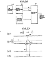
- the senor 5 or 5' outputs a detection signal as shown in Fig. 27fb) in dependence on the positional relation relative to a line segment 95 as shown in Fig. 27(a).
- the detection signal has a symmetrical wave form relative to the center position A of the line segment 95.
- a signal generating circuit 96 as shown in Fig. 26 has a suitable threshold Vs as shown in Fig. 27(b) which is smaller than the peak value of a detection signal generated by the sensor 5 and larger than an output level at the time when the line segment is detected. Further, it outputs a signal S 1 shown in Fig. 27(c) at the time when the detection signal generated by the sensor 5 becomes larger thnn the threshold Vs and moreover output a signal S 2 shown in Fig. 27(d) at the time when the detection signal of the sensor 5 becomes smaller than the threshold Vs.
- Both the signal S 1 and S 2 are inputted into a processing circuit 97, while a signal indicative of distance of movement of the vehicle 10 is inputted thereinto from the distance detector 44 as shown in Figs. 14 and 17.
- the processing circuit 97 receives from the distance detector 44 signals indicative of movement distances A1 and A 2 at the time when the signal S 1 and S 2 are inputted thereinto whereby a movement distance D of the unattended vehicle at the time when the sensor 5 moves past the center position of the line segment 95 is obtainable by the following formula (15).
- reference letters a, b and c designate an output signal from the sensor 5 respectively in the case where the sensor 5 is placed at a different height.
- the processing circuit 97 executes processing for each signal in accordance with the following formula (15). Each of the results obtained by processing represents a movement distance D indicative of the center position of the line segment 95.
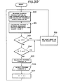
- n thresholds V sl , V s2l --- V sn as shown in Fig. 29 and then obtaining an average value D' among movement distances D 1 , D 2 --D at the center position of the line segment obtained with respect to each of the thresholds in accordance with the following formula (16), a distance of movement at the center position of the line segment can be obtained more stably and exactly.
- Each of line segments 2a, 2b and 2c constituting the ground mark 2 shown in the drawing is made of aluminum tape having a width of 5 cm and a distance between both the line segments 2a and 2c is set to 80 cm.
- a metal detecting sensor is employed for the sensor for this case and a speed of the vehicle (having, for instance, a total length of 2,130 mm) when the latter moves past the ground mark 2 is set to 4 Km/h.
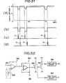
- Output voltage V from the sensor varies as illustrated in Fig. 31(a). As is apparent from the drawing, output voltage decreases from a saturated value (for instance, 10V) at every time when the vehicle moves past the line segments 2a, 2b and 2c. It should be noted that wave forms of output voltage appearing when it moves past them are different from one another due to movement of the vehicle in the vertical direction and inclination of the same.
- the signal generating circuit 96 shown in Fig. 26 is constructed, for instance, as illustrated in Fig. 32.
- voltage signal from the sensor is applied to the minus side input of a subtraction circuit 962 via an input terminal 961.
- threshold voltage (9V) is applied to the plus side input of the subtraction circuit 962 from a threshold setting unit 963.
- the subtraction circuit 962 makes subtraction with the above-mentioned two inputs and thus obtained subtraction signal is applied to schmitt circuit 964.
- This schmitt circuit 964 eliminates fine ripple noises included in the subtraction signal in response to receiving of the latter and signal as shown in Fig. 31(b) is then outputted therefrom.
- a distance of movement of the vehicle at the time when the sensor moves past the center position 95 (2a, 2b, 2c) is obtained.
- the time point (time) when the sensor movcs past the center position of the line segment 95 may be detected in the case where the vehicle moves at a constant speed.
- the distance detector 44 is typically constituted by a pulse encoder operatively associated with wheels on the vehicle 1 and means for counting output pulses from the encoder.
- the existent position (x, y) of the vehicle in the x-y coordinate system can be obtained in accordance with the following formulas (17) when the direction detector 43 and the distance detector 44 . are used to this end.
- ⁇ does an inclination of the vehicle.relative to x-coordinate (relative to the direction of movement of the vehicle)
- (x 0 , Y O ) does coordinate of the starting point of the vehicle.
- gyrocompass as means for measuring the direction of movement of the vehicle 1, gyrocompass, terrestrial magnetism vibration gyro, rate gyro, laser gyro and device for sensing the direction of movement by difference in number of rotations of left-handed and right-handed wheels are proposed. Further, the existent position of the vehicle may be measured directly by a radio wave measuring method.
- a certain four-wheeled vehicle has the minimum turning radius of 4.1 m at a moving speed of 1 m/sec under the operative condition that the body of the vehicle does not slide in the lateral direction.
- the optimum distance between the adjacent ground points is determined, it is generally determined in the range of 1/50 to 4 times of the minimum turning radius by using the latter as a reference. Determination of the range in that way is made in view of the fact that when the aforesaid distance is determined longer than 16 m that is 4 times of the minimum turning radius, unpractical delay of steering occurs during turning movement at a corner and in contrast with the foregoing case when it is determined shorter than 8 mm that is 1/50 times of the minimum turning radius, too long time is required for calculating the existent position of the vehicle and thereby undesirable delay of steering occurs.
- a radius of curvature of a circle which is defined by the adjacent three ground points among a series of ground points is determined larger than the aforesaid minimum turning radius, wherein the distance between the adjacent two points is determined in the above-described manner.
- the distance between the adjacent ground points during movement at a high speed is required to be widened in comparison with movement at a low speed.
- the radius of curvature of a circle at a low speed is required to be enlarged in comparison with movement at a low speed.
- the vehicle is steered under control in accordance with a steering angle command which is issued while the position of the series of ground points is utilized as target ground point.
- the steering angle command ⁇ required for orienting toward the target ground point P(x p , y p ) can be obtained by observing the existent position S(x , y ) and the moving direction ⁇ and using the formula (19).
- a first method is such that a predetermined range is provided for the target point, it is considered that the vehicle reaches the target point when it enters the aforesaid range and then the next point is taken as new target point.
- a predetermined range is provided for the target point, it is considered that the vehicle reaches the target point when it enters the aforesaid range and then the next point is taken as new target point.
- an area within a circle having a radius R with the target point P located at the - center thereof is defined as a range for the target point.
- a distance a between the target point P and the existent position S(x ,y ) of the vehicle is calculated and when it is found that this distance a is smaller than the radius R, it is considered that the vehicle reaches the target point.
- a second method is such that when the vehicle moves by the range which is considered as a fact that it reaches the target point, the next point is taken as new target point from the time when it moves by in that way.
- the time when the vehicle moves past the target point is determined in the following manner.
- the current position of the vehicle is represented by S t and the position of the same located before a certain unit time is represented by S t-1 . Then, a distance a t between the position S and the target point P and a distance a t-1 between the position S t-1 and the target point P are calculated, and decision is made such that the time when the following condition is established is considered as the time when the vehicle moves past the target point.
- Step 200 the current position s t and the direction ⁇ t of the vehicle are measured (Step 200).
- a distance at between the current position S t and the target ground point P is calculated (Step 201).
- Step 202 it is discriminated whether the calculated distance at is smaller than a predetermined radius S or not (Step 202).
- the program goes to Step 203 under the condition that it is considered that the vehicle reached the target ground point P.
- Step 203 a ground point next to the series of ground points on the planned moving passage is taken as new target ground point and then the program returns to Step 200.
- the program goes to Step 204 because the vehicle fails to reach the garget ground point P.
- Step 204 it is discriminated whether the distance at is larger than a t-1 as measured before a certain unit time or not.
- the vehicle moves away from the target point P.
- this time is taken as the time when the vehicle moves past the target point P and then the program goes to Step 203.
- the program goes to Step 205.
- the program since a distance a t-1 before a certain unit time is not existent when a distance a t is first calculated after new target point is determined, the program jumps over Step 204.
- a steering angle command ⁇ is calculated in accordance with the formula (19) and at Step 216 the steering angle command ⁇ is outputted.
- Fig. 37 is graph which illustrates the results of practical movement of a four-wheels vehicle 1 to which the above-mentioned controlling method is applied.
- the practical passage as identified by a real line in the drawing illustrates a locus of center point of the line segment which extends between both the left-handed and right-handed wheels of the vehicle.
- the passage is constituted by linear lines and arches having a radius of 6 m and a distance between target points is set to 50 cm. In the drawing, however, target points are plotted at every 2 meters for simplification.
- the vehicle 1 is a four-wheeled electrically driven motorcar having fore steering wheels and rear driving wheels. Detection of the direction of movement of the vehicle is effected with the use of a gyrocompass and the current position of the vehicle is obtained by a combination of moving distance as measured by a pulse encoder fitted to a wheel and the direction of movement of the vehicle. The maximum operating angle of a steering handle is net to 30°. Moving experiments were carried out on an asphalt paved ground and a speed of the vehicle was set to 4 km/h.
- Sampling time was set to 130 m sec to meet response of the steering system. As will be apparent from the drawing, a sufficiently high accuracy in guiding of movement of the vehicle could be obtained. Processing time for executing the steps as shown in the flow chart.amounts to about 10 m sec in terms of assembler worlds. Accordingly, the residual sampling time of 120 m sec can be used for the purpose of controlling of an obstacle sensor, self-diagnosis, man-machine interface or the like.
- the present invention should not be limited only to four-wheeled vehicle. Alternatively, it may be equally applied to three-wheeled vehicle, both wheel independently driven vehicle, crawler, all direction movable vehicle, six-wheeled vehicle, double feet walking machine, multi-feet walking machine or the like unattended vehicle.
- a four-wheeled vehicle is illustrated as an equi-two-wheeled vehicle in the same manner as in Fig. 33.
- an imaginary wheel lb' is located at the position forwardly of a fore wheel la that is a non-steering wheel by a distance equal to the length of a wheel base of the vehicle
- coordinates M' (x m , y m ') of the steering wheel 1b' are represented in accordance with the following formulas on the assumption that coordinates of the fore wheel la are identified by M(x m ' y m ), the length of the wheel base is identified by K and the direction of movement of the vehicle is identified by ⁇ .
- a steering angle ⁇ ' for orienting the imaginary steering wheel lb' toward a target point P through which the vehicle is to move is botainable in the following manner.
- an angle ⁇ m ' formed between the x-coordinate and a line segment PM' is represented by the following formula.
- a steering angle ⁇ of the actual steering wheel 1b is an angle which has its mark reversed to that of the steering angle ⁇ ' and therefore it is represented by the following formula.
- the steering angle ⁇ can be finally represented by using the formula (24) as well as the formulas (21) to (23) in the following.
- a steering angle t required for orienting toward the target point P (x p , y p ) can be obtained by measuring the current position M (x m , y m ) of the vehicle and the orientation angle ⁇ of the same and then putting the results of measurement into the formula (25).
- a rear wheel steering vehicle of which rear wheel lb is contrlled to assume the steering ⁇ and a fore wheel steering vehicle of which imaginary steering wheel lb' is controlled to assume the steering angle ⁇ ' have the same center 0 of turning movement and the same radius of turning movement and moreover they have an approximate transitional response characteristic relative to a predetermined.
- An orientation angle ⁇ of a vehicle can be measured, for instance, by means of a gyrocompass, as mentioned above. Further, the current position M(x m , y m ) of the vehicle can be obtained from the formula (17).
- Fig. 39 illustrates steps of guiding of a vehicle wheel steering vehicle along a passage which is previously taught in the form of a series of ground points, by using the steering angle ⁇ which has been obtained in the above-described manner.
- Fig. 39 The steps in Fig. 39 are executed by using position M' in place of position S in Fig. 34 and moreover using positions M t-1 and M t in place of positions S t-1 and St in Fig. 35.
- Step 300 the current position M t ' of the vehicle and the direction of movement of the same (orientation angle) ⁇ t are measured, and the imaginary current position M t ' of the vehicle is calculated in accordance with the formula (21). Then, a distance at between the thus obtained imaginary current position M t ' and the target point P is calculated (Step 301).
- Steps 302 to 307 processing similar to the content at Steps 202 to 207 in Fig. 36 is executed but at Step 305 the steering angle command ⁇ is processed with reference to the formula (25).
- a vehicle can be oriented toward a target point smoothly and with high response in the same manner as in the case where the fore wheels are steered.
Abstract
Description
- The present invention relates to a method of guiding an unmanned vehicle.
- In order to properly guiding an unmanned vehicle, there is a necessity for knowing the position where the vehicle is located on a moving passage. Japanese Patent Application No. 93406/1982 discloses a technical concept that a plurality of ground marks are placed at proper positions on the moving passage and the correct position of the vehicle can be measured by detecting them on the vehicle side is disclosed.
- However, this conventional method has a problem that means for detecting the ground marks requires a wide visual scope, and producing such detecting means is expensive.
- On the other hand, a so-called navigational guiding method for guiding a vehicle along a previously taught moving passage has been hitherto employed in aircraft or ship. When this navigational guiding method is carried out, direction detecting means and movement distance detecting means are used to estimate the current position of an unmanned vehicle, but error in estimated value of position is increasingly accumulated due to slippage of the vehicle, ruggedness of ground or the like factor. Accordingly, the current correct position of the vehicle is obtained and the estimated value is then corrected with reference to the current correct position.
- In this case, it is naturally necessary to teach the position of the ground marks previously.
- . To teach positions of each ground marks and certain points on the passage, these positions must be measured previously. However, such measurement requires long time and many manhours. Particularly, in the case where there is a necessity for frequently changing the moving passage, it is very troublesome to carry out such measurement.
- In the navigational guiding process, the position of each ground point on the moving passage is successively given as target position for the vehicle, but there arises a problem that malfunction such as delayed steering or the like takes place due to improper timing of giving target points.
- Further, in the conventional navigational guiding process, controlling is effected for orienting the fore wheels as seen in the direction of movement toward the target point. However, in the case where a fore wheel stearing vheicle is operated or in the case where a rear wheel stearing vehicle is driven in the backward direction, the navigational guiding process fails to function properly.
- Hence, the present invention has been made with the foregoing background in mind.
- An object of the present invention is to provide a method of guiding an unmanned vehicle which assures that the method can be practiced with the use of inexpensive ground mark detecting means.
- Another object of the present invention is to provide a method of guiding an unmanned vehicle which assures that teaching of a moving passage is effected very simply and moreover changing of the moving passage is carried out easily.
- Still another object of the present invention is to provide a method of guiding an unmanned vehicle which assures that the vehicle moves on a moving passage having complicated curved portions without any occurrence of delayed steering.
- Further another object of the present invention is to provide a method of guiding an unmanned vehicle which assures that guiding of the vehicle is effected with a proper steering angle in the case where rear wheels as seen in the direction of movement of the vehicle serves as steering wheel.
- To accomplish the above objects, it is proposed according to the present invention that a certain number of ground marks each of which comprises a plurality of line segments are placed on a moving passage of an unmanned vehicle and a relative positional relation between the ground mark and the vehicle is obtained by measuring amount of movement of the vehicle between the adjacent line segments when the vehicle moves across the ground mark.
- When the navigational guiding process is employed, ground marks are placed at a plurality of predetermined positions within the moving area of the vehicle and a moving passage of the vehicle is determined by selectively assigning the ground marks. Further, by interpolating an area between the adjacent assigned ground marks, the position of each of ground points on the moving passage is obtained and the thus obtained position is then taught to the vehicle.
- Further, according to the invention, a distance between the current position of a target ground point on the moving passage and the current position of the vehicle is obtained during navigational guiding and when the distance becomes shorter than a predetermined one or it increases as the vehicle goes on, the current target ground point is changed to next one.
- Furthermore, according to the invention, an imaginary steering wheel is supposed at the position located forwardly of a non-steering wheel by a length of the wheel base of the vehicle in the case where the rear wheel as seen in the direction of movement of the vehicle serves as steering wheel. A steering angle is then obtained when the imaginary steering wheel is oriented toward the current target ground point on the moving passage and a value of the steering angle of which sign is reversed is used as a steering command value.
- The invention is illustrated by the following drawings in which:
- Figs. 1, 7, 9 and 11 are perspective views respectively which schematically illustrate arrangement of ground marks on a moving passage;
- Figs. 2, 4, 8, 10, 12, 20 and 21 are schematic views respectively which illustrate structure of a ground mark and a principle for detecting the position of an unmanned vehicle with the use of the ground mark;
- Figs. 3 and 5 are wave form diagrams respectively which illustrate a wave form of output signals from a sensor when a ground mark as shown in Figs. 2 and 4 is used;
- Figs. 6, 18 and 19 are schematic views respectively which illustrate other structure of a ground mark;
- Fig. 13 is a schematic view which illustrates arrangement of ground marks within the moving area of a vehicle and a moving passage determined by some of the ground marks;
- Fig. 14 is a block diagram illustrating one example of an apparatus for practicing a navigational guiding process for the vehicle;
- Fig. 15 is a flow chart which illustrates operation of the apparatus in Fig. 14;
- Fig. 16 is a schematic view illustrating a principle for estimating the position of the vehicle;
- Fig. 17 is a block diagram which schematically illustrating an apparatus for teaching a moving passage of the vehicle;
- Figs. 22 and 23 are a vertical sectional view and a side view illustrating a wheel in which a sensor is accommodated;
- Fig. 24 is a vertical sectional view illustrating arrangement of a sensor in a wheel with rotating means incorporated therein;
- Fig. 25 is a perspective view illustrating the structure of a ground mark;
- Fig. 26 is a block diagram showning an apparatus for detecting that a sensor moves past the center of a line segment constituting the ground mark;
- Fig. 27 is a timing chart showing the operation of the apparatus in Fig. 26;
- Fig. 28 is a wave form diagram illustrating output signals from a sensor which is mounted at different levels;
- Fig. 29 is a wave form diagram of an output signal with a plurality of thresholds placed thereon;
- Fig. 30 is a schematic view illustrating one example of ground mark and a moving track of the vehicle which moves across the ground mark;
- Fig. 31 is a time chart illustrating function of the apparatus in Fig. 27 when the ground mark as shown in Fig. 30 is used;
- Fig. 32 is a circuit diagram illustrating a concrete example of the interruption signal generating circuit in Fig. 27;
- Fig..33 is a schematic view illustrating a principle for obtaining a steering angle;
- Fig. 34 is a schematic view illustrating a scope of a target ground point;
- Fig. 35 is a schematic view illustrating a method of determining whether the vehicle moves past the target ground point or not;
- Fig. 36 is a flow chart illustrating steps for guiding movement of the vehicle;
- Fig. 37 is a graph illustrating the result of guiding of movement of the vehicle in the case where the steps as shown in Fig. 36 are practiced;
- Fig. 38 is a schematic view illustrating how to obtain a steering angle relative to a rear wheel driving vehicle; and
- Fig. 39 is a flow chart illustrating steps in the case where movement of the rear wlieel driving vehicle is guided.
- Now, the present invention will be described in a greater detail hereunder with reference to the accompanying drawings which illustrate preferred embodiments thereof.
- In Fig. 1
reference numeral 1 designates an unmanned vehicle on which no operator rides,reference numeral 2 does a ground mark,reference numeral 3 does a track on which it is planned that theunmanned vehicle 1 moves,reference numeral 4 does a locus along which theunmanned vehicle 1 has moved actually andreference numeral 5 does a sensor which is mounted on .theunmanned vehicle 1. - The
unmanned vehicle 1 is equipped with a direction detector and a running distance detector (both of which are not shown in the drawing) and automatic steering for alowing thevehicle 1 to move on thetrack 3 is carried out by estimating with the use of the above-mentioned detectors the current position where the vehicle is located at present. - As is apparent from Fig. 2, each of the
ground marks 2 is constituted by threeline segments passage 3 in the transverse direction. Theline segments line segment 2b diagonally extends between the tail end of theline segment 2a and the leading end of theline segment 2c. With respect to theground mark 2, it is preferable that theline segments passage 3 and thepassage 3 extends through the middle point of each of the line segments. - Metallic plate, metallic tape, metallic wire or the like is employed as material constituting each of the line esgments on the assumption that floor is built by concrete without any piece of metallic material embedded therein. Further, in the illustrated embodiment, a metallic material sensor, for instance, eddy current sensor is employable for the
sensor 5 mounted on the vehicle to detect line segments. For the sake of convenience, one example of a combination of material of the ground mark and sensor will be shown on the following table.

- Next, description will be made as to the case where the
unmanned vehicle 1 moves past theground mark 2 and thesensor 5 scribes thelocus 4 as represented by a solid line in Fig. 2 as a result of movement of the vehicle in that way. When a distance L between theline segments ground mark 2 is sufficiently small, it can be considered that thelocus 4 is an approximately extending linear line. It should be noted that description has been made on the assumption that thelocus 4 is scribed when thevehicle 1 moves from the lower side toward the upper side as seen in the drawing. - First, the
locus 4 intersects theline segment 2a at point P1, then it does theline segments 2b at point P2 and finally it does theline segment 2c at point P3. As a result, thesensor 5 generates signals which inform that thesensor 5 detects theline segments - When it is assumed that the
vehicle 1 moves at a constant speed, a ratio of distance L1 between point P1 and P2 to distance L2 between P2 and P3 is equal to a ratio of time interval T1 to time interval T2 in Fig. 3 and moreover it is equal to a ratio of length ℓ1 to length ℓ2. - Accordingly, an amount of course deviation ℓ3 of the vehicle from the center line on the ground mark 2 (which is identical to the passage 3) can be determined by receiving output signals from the
sensor 5 and measuring time intervals T1 and T2. This is because amount of the course deviation ℓ3 can be expressed as follows:
mark 2. - Incidentally, in the illustrated embodiment where the vehicle is equipped with a
single sensor 5, the width of the ground mark, that is, (ℓ1 +ℓ2) defines a scope of detection. In the case where the vehicle is equipped with twosensors 5 which are located in a spaced relation in the transverse direction it results that a scope of detection can be widened by a distance between the sensors. - Next, description will be described below as to how an occurrence of incorrect sensing of the ground mark is prevented.
- In the case where metallic material is used for the
line segments 2a to 2c, thesensor 5 may sense theground mark 2 incorrectly when certain article made of metallic material is placed on the floor. Similarly, in the case where white lines are employed for theline segments 2a to 2c, incorrect sensing may be effected when the floor has a spot which is coated with white ink. - In order to prevent an occurrence of incorrect sensing, it is recommendable that one or more additional line segments are provided at the position located before or after the
ground mark 2. - Fig. 4 illustrates the case where
new line segments ground mark 2 which compriseslines segments line segments line segments sensor 5 on thelocus 4 are as shown in Fig. 5. - Refering to Fig. 5, when speed of the
vehicle 1 is kept constant, ratio of time interval T3 to time interval T4 or T5 relative to output signals from the sensor does not vary irrespective of how the vehicle is deviated from the correct course but ratio of time interval T1 to time interval T2 varies in dependence on an amount of deviation of the vchicle from the course. Namely, sensor signals appear at time intervals T41 T5 and T3t as long as any signal outputted from thesensor 5 does not contain noise. Accordingly, it can be discriminated with reference to ratios relative to time intervals as mentioned above whether or not a detection signal from the sensor is generated by line segment or noise. - Incidentally, in the case where speed of the vehicle varies remarkably, it is recommendable to measure a distance of movement of the vehicle for each of time intervals instead of employment of the time intervals from the sensor.
- In the example as shown in Fig. 4, two
additional line segments line segment 2a. It is obvious that the same advantageous effects are obtainable when one or more than three additional line segments are provided at the position before theline segment 2a or after theline segment 2c. - Incidentally, a shape of the
ground mark 2 should not be limited only to that as shown in Fig. 2. Alternatively, a ground mark 2' including line segments 2'a, 2'b and 2'c of which both the sides are cut off as shown in Fig. 6 may be employable. Further, ground marks whose shape is reversed to those shown in Figs. 2 and 6 may be employable also. - Further, by locating the
ground mark 2 at a known position on thetrack 3, it is possible to detect the current correct position of the vehicle when the latter moves past theground mark 2. Since the current correct position can be sensed in that way, the existent position which is estimated continuously on the vehicle side can be corrected to the above-mentioned current correct position at every time when the ground mark is detected. - In the case where a distance between both the
line segments - Fig. 7 shows an embodiment in which two
ground marks 6 each of which is constructed by twoline segments unattained vehicle 1 is equipped with twosensors 5 and 5' to guide movement thereof. - As is apparent from the drawing, both the
line segments line segment 6a extends at a right angle relative to the planned movingtrack 3 and theline segment 6b intersects thelino segment 6a at the one end (intersection 0) of theline segment 6a at an inclination angle of ϕ. - When it is assumed that the
unattained vehicle 1 moves past theground mark 6 and thereby loci 7 and 8 as illustrated in Fig. 8 are scribed by means of thesensors 5 and 5', thelocus 7 first intersects theline segment 6a at point P11 located on theline segment 6a and then it intersects theline segment 6b at point P12 located on theline segment 6b. Similarly, thelocus 8 first intersects theline segment 6a at point P11' located on theline segment 6a and then it intersects theline segment 6b at point P12' located on theline setment 6b. Accordingly, there are generated signals which inform that thesensor 5 detects the line segments by intersections P11 and P12 and the sensor 5' detects the line segments by intersections P11' and P12'. - Here, description will be made as to a principle for obtaining an angle of 6 which is formed between the
line segment 6a and the direction of movement of the unattended vehicle 1 (the direction of extension of theloci 7 and 8). - Refering to Fig. 8, the point P0 represents the position where the
sensor 5 is located when the sensor 5' reaches the point P11'. Since a triangle P11, P11', P0 defined by intersections P11 and P11' and position P0 is a right-angled triangle, an angle of 0 is represented by the following formula (1).
sensors 5 and 5'. - Accordingly, the aforesaid angle e can be obtained in accordance with the formula (1) by measuring the distance
P 0 P 11 vehicle 1 from the time when the sensor 5' reaches the intersection P11' to the time when thesensor 5 reaches the intersection P11, wherein measurement is achieved by using means, for instance, length measuring ring or the like. - Next, description will be made below as to how the position where intersections P11 and P11' are located is obtained. Distance
OP 11 line segments OP 11 ' between the intersection O and the intersection P11' are represented by the following formulas (2).
line segments - Accordingly, by measuring the distance
P 11 P 12 from the time when thesensor 5 detects theline segment 6a to the time when it detects theline segment 6b as well as the distanceP 11 'P 12 ' from the time when the sensor 5' detects theline segment 6a to the time when it detects theline segment 6b by using means, for instance, length measuring ring or the like, the position of thesensors 5 and 5' as seen in the transverse direction relative to theline segment 6a can be obtained with reference to the aforesaid distances,angle 8 and angle - When it is assumed that the position where the middle point between both the
sensors 5 and 5' moves across theline segment 6a is identified by Q, the distance OQ as measured from the reference point O to the aforesaid point Q is represented by the following formula.
passage 3 extends across theline segment 6a is identified by R, an amount of course deviationRQ of thevehicle 1 from the aforesaid point R is represented by the following formula (4).

- The amount of course deviation obtained in the above-described manner is typically utilized as an information for controlling steering of the vehicle so as to cancel this amount of course deviation. Further, it may be utilized for correcting the estimated position of the vehicle when navigational guidance to be described later is carried out. Namely, since a true coordinate position of the vehicle can be detected with reference to the coordinate position where ground marks 2 or 6 is placed and the aforesaid amount of course deviation, the existent position which is estimated on the vehicle side during navigational guiding can be corrected with reference to the above-mentioned true coordinate position.
- Incidentally, due to the fact that the direction of movement of the vehicle can be detected in accordance with the formula (1) in the embodiment as illustrated in Fig. 7, various induction inclusive posture angle of the
vehicle 1 can be achieved. When navigational induction is carried out in the above-described manner, the direction of movement of the vehicle is measured with the use of a rate gyroscope or the like means. At this moment the measurement results obtained by using the gyroscope or the like means can be properly corrected with reference to the direction of movement of the vehicle which is detected in compliance with the embodiment as illustrated in Fig. 7. - When ground marks 10 as illustrated in Fig. 10 are used, both the position of the
vehicle 1 and the direction of movement of the same can be detected with the use of asingle sensor 5. - As shown in Fig. 10, each of the ground marks 10 is constituted by two
line segments 10a and 10d which are in parallel with one another and other twoline segments 10b and 10c which are interposed between the twoline segments 10a and 10d in such a manner as not to be in parallel with them. In the illustrated embodiment arrangement is so made that theline segments 10a and 10d extend at a right angle relative to the planned movingpassage 3 or thevehicle 1 and theline segments 10b and 10c at least intersect the planned movingpassage 3. - When it is assumed that the
unattended vehicle 1 moves past theground mark 10 and thereby thesensor 5 scribes alocus 4 as represented by a dotted line in Fig. 10, thelocus 4 first intersects the line segment 10a at point m1 and then it intersects theline segment 10b at point m2. Further, it intersects the line segment 10c at point m3 and finally it intersects theline segment 10d at point m4. Coordinates (x2, y2) of the intersection m2 and coordinates (x3, y3) of the intersection m3 can be obtained by measuring four distances between the intersections, that is,m 1 m 2 ,m 2 m 4 , m 1 m 3 m 3 m 4 . - Specifically, in the case where such a x-y coordinate system as illustrated in Fig. 10 is applied to the Z-shaped
ground mark 2 in Fig. 2, among three intersections P1, P2 and P3 where thelocus 4 of thesensor 5 intersects theground mark 2 coordinates (x, y) of the intersection P2 are obtainable in accordance with the following formulas by utilizing distances L1 and L2 between the intersections.
- Incidentally, in the above-noted formulas V designates width of the
ground mark 2 as seen in the x-direction, while Y does a distance between line segments as seen in the y-direction. - Also coordinates (x2, y2) of the intersection m2 and coordinates (x3, y3) in the x-y coordinate system in Fig. 10 can be obtained in compliance with the above-mentioned step of obtaining coordinate (x1, x2) of point P2 with the use of distances between the intersections
m 1 m 2 , m 2 m 4 m 1 m 3 , m 3 m 4 . - An angle of θ1 formed by the
ground mark 10 and theline segment 10d is given in accordance with the following formula (6).
- When a reference coordinate position of the
ground mark 10 is identified by Z0 (xz0, yz0), coordinates (x4, y4) of the intersection m4 are determined in accordance with the following formulas.
- Accordingly, by detecting intersections m1 to m4 with the aid of the
sensor 5 and measuring distances between the intersections, that is,m 1 m 2 , m 2 m 3 m 3 m 4 vehicle 1 is located can be obtained in accordance with the formula (7). Incidentally,line segments 10b and 10c are not necessarily parallel with each other.
ground mark 2 and the position T where the sensors intersects theline segment 2b can be represented in accordance with the following formula (8).
- Further, an angle of 83 formed by the angle φz0 indicative of the direction of extension of the
ground mark 2 and the angle φ indicative of the direction of movement of thevehicle 1 can be represented in accordance with the following formula (9).
- where L represents a distance between both the
sensors 5 and 5'. Further, the angle φz0 indicative of the direction of extension of theground mark 2 can be represented in accordance with the following formula (10).
- Further, coordinates of the reference position z0 (xz0, yz0) can be represented in accordance with the following formulas (11).

- It should be noted that a condition of θ2 = const = tan-1 (c/b) is applicable to the above formulas and xt and yt represent coordinates of the position T.
- Accordingly, by measuring Δℓ with the use of length measuring means, the angle φ indicative of the direction of the
vehicle 1 can be obtained from the formula (10) with reference to the above-noted Δℓ and the angle φz0 indicative of the direction of extension of theground mark 2. Further, when the coordinates (xz0, yz0) of the reference position of theground mark 2 and the angle φz0 indicative of the direction of extension of theground mark 2 are given and the distance e is measured with the use of length measuring means, the coordinates (xt, yt) of the position T, that is, coordinates representative of the position where thevehicle 1 is located are obtainable from the formula (11). - Incidentally, in the case where a speed of movement of the
vehicle 1 is kept constant, it is possible to measure distances of A1, ℓ1 and 12 with reference to time interval of generation of output signals from the sensor 5'. - Next, description will be made below as to a method of teaching a moving track for an unmanned vehicle as well as a method of guiding movement of the same in accordance with the present invention.
- As shown in Fig. 13, a plurality of ground marks Z12 to Z76 are previously arranged within a moving area for the
unmanned vehicle 1. It should be noted that each of the ground marks as mentioned above is placed at the predetermined position while extending in the predetermined direction. - Fig. 14 schematically illustrates one example of an apparatus for carrying out the method of teaching a moving passage for an attended vehicle as well as the method of guiding movement of the same. The position of all ground marks Z12 to Z76 and the direction of extension of the same are stored in an all ground mark coordinate
memory 30. Apassage setting device 31 is manually operated when a moving passage is determined, and a required moving passage is determined by successively selecting and assigning the ground marks Z12 to Z76. For instance, in the case where a moving passage as represented by areal line 50 in Fig. 13 is to be set, a plurality of ground marks are assigned in accordance with the order of Z21 → Z 41 → Z61 → Z72 → Z74 → Z65 → Z54 → Z43 → Z23 → Z12 → Z21, wherein the ground mark Z21 serves as starting point and terminating point. - A passage teaching computor 32 successively reads from the all mark coordinate
memory 30 positional coordinates and direction for each of the ground marks assigned by thepassage setting device 31 and thereby obtains positional coordinates of each ground point between the adjacent ground marks by linear or arch interpolation. Then, data indicative of positional coordinates and direction relative to each of the ground marks as well as data indicative of positional coordinates relative to each of ground points obtained by interpolation in that way are transmitted via atransmitter 33. - Next, description will be made below as to steps of processing to be performed by the
passage instructing computor 32 or the like with reference to Fig. 15 that is a flow chart. When a ground mark Z1 (Z21 in the case of the track 50) serving as starting point is inputted atStep 100, data indicative of its coordinates (xz1, yz1) and data indicative of direction φz1 are transmitted from the transmitter 33 (Step 101). Next, i is rewrote to 2 (Step 102) and data indicative of coordinates (xzi, yzi) and direction (φzi) relative to the assigned ground mark Zi are inputted (step 103). - In the case when this inputting fails to be effected within a predetermined period of time, this flow is completed. On the contrary, in the case where inputting has been effected within a predetermined period of time, the program goes to Step 105 (Step 104). At
Step 105 comparison is made between direction φzi of the ground mark which has been inputted at this time and direction φzi-1 of the ground mark which was inputted at the preceding time. When it is found that the former is identical to the latter, the program goes to Step 106. If not, the program goes to Step 107. - At Step 106 a linear line extending between ground marks zi and Zi-1 is interpolated by series of ground points, while at
Step 107 both the ground marks zi and zi-1 are connected to one another by an assigned arch and then interpolated by a series of ground points. - Specifically, when it is assumed that for instance, Zi ground marks Zi and Zi-1 are ground marks Z61 and Z41 in
Fi g. 13, the intermediate area between both the ground marks is interpolated by a series of ground points and positional coordinates relative to each ground point among the series of ground points are objtained atStep 106. - Similarly, in the case where ground marks Zi and Zi-1 are ground marks Z72 and Z61 in
Fi g. 13, the intermediate area between both the ground marks is interporated with tespect to an arch by a series of ground points and positional coordinates relative to each ground point on the thus interpolated arch are obtained atStep 107. - Coordinate data indicative of position of each ground point among the series of ground points between the ground marks Zi and Zi-1 as obtained by interpolation, coordinate data (xzi, yzi) indicative of position of the ground mark Z3 and data indicative of direction φz of the same are transmitted from the
transmitter 33 atStep 108. - After i has an increment by 1 at
Step 109, the step is caused to return toStep 103. - Thus, in the case where an assigned moving passage is the moving
passage 50 as shown in Fig. 15, data indicative of positional coordinates and direc- tion of the ground marks Z21, Z41, Z61 --- Z12, Z21 and data indicative of positional coordinate of each ground point between the adjacent ground marks are transmitted from thetransmitter 33. - The above-mentioned data transmitted from the
transmitter 33 are received by areceiver 40 mounted on thevehicle 1. Data indicative of coordinates and direction of each of the ground marks on the moving passage are successively stored in a mark coordinatememory 41, while coordinate data indicative of position of each ground point between the adjacent ground marks are successively stored in apassage memory 42. - Thus, teaching of the passage inclusive position and direction of extension of each of the ground marks has been completed by way of the steps as mentioned above.
- Next, description will be made below as to control for causing the
unmanned ehicle 1 to move along n predetermined passage (for instance, the passage in Fig. 15) by using the stored data relative to the passage. - Refering to Fig. 14, a
direction detector 43 is constructed in the form of a rate gyroscope which is adapted to detect direction of movement of thevehicle 1 by detecting an amount of displacement (angular speed) in the direction of movement of thevehicle 1 and integrating it. Arunning distance detector 44 detects a distance of movement of thevehicle 1 which moves momently by using the number of revolutions of wheels or the like. Further, amark detector 45 detects existence of line segments constituting the ground mark when thevehicle 1 moves across the ground mark. Incidentally, thisdetector 45 corresponds to twosensors 5 and 5' in Fig. 11. - A estimated vehicle
position processing circuit 46 is effective for estimating the current position of thevehicle 1 in response to signals indicative of direction and running distance of thevehicle 1 which are momently outputted from adirection detector 43 and arunning distance detector 44 and outputs a signal indicative of the estimated position of thevehicle 1. - A vehicle
position processing circuit 47 obtains the position of thevehicle 1 relative to the ground mark with reference to each of output signals from therunning distance detector 44 and amark detector 45 and moreover specifically designates the ground mark detected by theground mark detector 45 with reference to signals outputted from the estimatedposition processing circuit 46 to indicate an estimated position of thevehicle 1. Then, data indicative of positional coordinates and direction of extension of the specifically designated ground mark are read from amemory 41 and the current correct position of thevehicle 1 in a x-y coordinate system representative of the passage thereof is obtained from the thus read data with reference to the position of thevehicle 1 relative to the ground mark. Thereafter, the estimated position obtained with the aid of the vehicle estimatedposition processing circuit 46 is corrected to the above-mentioned correct position. It should be noted that this position correction is carried out at every time when the vehicle moves past the ground mark. - A steering
command processing circuit 48 successively reads coordinate data relative to a series . of ground points on the passage stored in thepassage memory 42, that is, coordinate data relative to each ground point between the adjacent ground marks obtained by interpolation in response to signals added from the vehicle estimatedposition processing circuit 46 to indicate the estimated position of thevehicle 1 so that a steering command is issued to asteering mechanism 49 in order that thevehicle 1 follows the series of ground points. Incidentally, when a distance between the estimated position and the position of target ground points (the position of the series of ground points) is reduced shorter than a predetermined distance or the aforesaid distance becomes elongated gradually, the steeringcommand processing circuit 48 sets as new target ground point a ground point located next to the stored series of ground points. Description will be made later as to setting of the new target ground point. - According to the embodiment of the invention as described above a required passage can be taught merely by successively designating ground marks, that is, without any necessity for allowing the vehicle to move and moreover changing of the passage can be easily achieved. Further, the estimated position of the
vehicle 1 is corrected to a proper position at every time when thevehicle 1 moves past the ground mark while movement of thevehicle 1 is guided. Accordingly, movement of thevehicle 1 can be guided with high accuracy even when the passage has a long length. - Incidentally, the present invention should not be limited only to the above-mentioned embodiment in which the passage is taught via communication means. Alternatively, the passage for the
vehicle 1 may be guided with the aid of a calculator or the like means mounted on thevehicle 1 to instruct the moving passage therefor. Further, since the direction of movement of the vehicle can be detected when it moves past the ground mark, this leads to a result that detection output from thedirection detector 43 can be corrected. - Next, description will be made below as to another method of teaching a passage.
- This method of teaching a passage consists in that for instance, Z-shaped ground marks 2 as illustrated in Fig. 11 are disposed at proper positions in a moving area of the
vehicle 1, movement of thevehicle 1 is manually guided so as to allow it to move past the ground marks 2 and the position of each ground point on the moving passage is stored as a series of ground points with reference to the track of estimated position of thevehicle 1 at that time and that estimated positional coordinates of the ground mark on which the vehicle is adapted to move is obtained with reference to estimated position of the vehicle and the thus obtained estimated positional coordinates are stored as coordinate of the ground mark. - Now, in the case where the
vehicle 1 moves from position Pa(xa, ya) to position Pb(xb, yb) for a very short period of time At, position Pb(xb' yb) is represented by the: following formulas (12), when it is assumed that the direction of movement of the vehicle at position Pa is identified by φa the direction of movement of the same at position Pb is identified by φb and a distance between position Pa and Pb is identified by 1.
vehicle 1 can be estimated by totaling the initial position and the latter changed position. - Here, description will be made as to a principle for estimating position and direction of extension of the ground mark from the vehicle side.
- For instance, when the
sensors 5 and 5' mounted on thevehicle 1 as shown in Fig. 11 move across theground mark 2 while scribingloci 4 and 4', positional coordinates Z0(xz0,yz0) and direction φz0 are represented in accordance with the formulas (10) and (11). Accordingly, direction φz0 of theground mark 2 can be estimated from the formula (10) by obtaining an angle of 83 on the basis of the formula (9) and then detecting direction ; of movement of the vehicle on the vehicle side. Further, by obtaining distance e on the basis of the formula (8) and estimating position T (xt,yt) on the vehicle side at the time when the vehicle moves past the ground mark, position Z0(xz0,yz0) of theground mark 2 can be estimated with reference to the formula (11). - Further, this embodiment in which the moving passage is taught while movement of the
vehicle 1 is guided manually will be described below in association with a teaching apparatus as exemplified in Fig. 17. It should be noted that same or similar elements as those in Fig. 14 will be identified by same reference numerals. - According to this embodiment the ground marks 2 are previously disposed at a plurality of positions within a moving area of the
vehicle 1 in the above-described manner and movement of the vehicle is manually guided so as to allow it to move across them whereby running locus of the vehicle is taught as moving passage. - Refering to Fig. 17, estimated
position processing circuit 46 outputs to apassage memory 60 data indicative of estimated position (x, y) of the vehicle while movement of the latter is guided manually and thereby positional coordinates relative to each ground point on the moving passage of the vehicle are successively stored in thememory 60. Namely, data indicative of passage of the vehicle are stored therein in the form of a series of ground points. - On the other hand, a coordinate-
direction processing circuit 61 estimates coordinates (x , y ) and direction φz0 of the ground mark in accordance with the formulas (8) to (11) so that data indicative of the thus estimated coordinates and direction are outputted to a mark coordinatememory 62. Thus, coordinate data and direction data relative to the ground mark are successively stored in thememory 62 in such a manner as illustrated in the drawing. - When the vehicle is caused to move once along a required moving passage in that way, teaching of the moving passage inclusive the position and direction of the ground mark is completed.
- On completion of teaching of the passage, movement of the vehicle along the instructed moving passage can be guided in the same manner as in the foregoing embodiment. Namely, data (x0,y0) (x l' y1) ---- stored in the
memory 60 are successively read therefrom as target position whereby movement of the vehicle along the series of ground points is guided. - Further, the estimated position of the vehicle is corrected with the use of data (Xz0, yz0), (xz1, Yzl) ---- and data φz0, φz1 ---- each of which is stored in the
memory 62, when the vehicle moves past the ground mark. Namely, the position of the vehicle is estimated in accordance with the principle as illustrated in Fig. 16 and an estimated value is corrected in dependence on the content of thememory 62 when the vehicle moves past the ground mark. - Incidentally, Z-shaped ground marks 2 are employed for the embodiment as illustrated in Fig. 11. Alternatively, a ground mark as illustrated in Fig. 8, 10 and 18 to 20 may be used. In short, any combination of ground mark by means of which the position of a vehicle can be detected and a sensor is employable.
- Accordingly, for instance, a landmark by means of which direction of movement of a vehicle can be detected is used as ground mark and a television camera for photographying the landmark is used as sensor so that the position of the vehicle can be detected with reference to the position and direction of the landmark appearing on the screen of the television.
- Here, ground marks 71 and 72 as shown in Figs. 20 and 21 will be described briefly.
Line segments 71a to 7le constituting theground mark 71 include intersections A, B, C, D and E at which they intersect alocus 71f of a sensor for detecting them. When length of line segments AB, BC, CD and DE between the adjacent intersections is represented by dl, d2, d3 and d4, positional deviation CO of the vehicle and inclination θ5 are obtainable in accordance with the following formulas (13).
line segment 71a and L2 represents a distance between both theline segments - The
ground mark 72 as illustrated in Fig. 21 is constituted by fourline segments 72a to 72d among which onlyline segments line segments 72a to 72d have intersections A, B, C and D at which they intersect alocus 72f of the sensor for detecting them. By measuring a distance AB and a distance BC, the position where the intersection B is located can be obtained in the same manner as described above. Further, by measuring a distance AC, adeclination angle 86 of the vehicle can be obtained in accordance with the following formula (14).
- It can not be specifically determined by the
declination angle 06 obtained in the above-described manner whether or not the vehicle is inclined rightward or leftward relative to the direction of movement of the vehicle. However, the direction of inclination of the vehicle can be specifically determined by measuring a distanceCU orAD. - As shown in Fig. 1, the
sensor 5 is mounted on the side wall of thevehicle 1. However, in the case where the sensor is constructed in such a manner as to magnetically detect the ground mark, it can be accommodated within the hollow space of awheel 80 as shown in Figs. 22 and 23. - In the
drawings reference numeral 81 designates a wheel surface structure made of rubber or the like material which is rotatably supported by means ofbearings 82. - When the
sensor 5 is an eddy current type sensor, it is constructed by coils and it is held - within the hollow space of the wheel in the downward direction. In this case a ground mark made of metallic material, ferrite or the like is subjected to function of magnetic field, causing alternate current to flow through thesensor 5. When thesensor 5 reaches the position where it is located above the ground mark, an intensity of electric current which flows through thesensor 5 varies under the effect of electromagnetic field whereby the fact that thesensor 5 is located above the ground mark can be detected. - Incidentally, in the case where the ground mark is constructed to generate a magnetic field, means for detecting the magnetic field is employed for the
sensor 5. - Fig. 24 shows a
wheel 86 in which amotor 85 serving as driving force power is accommodated. Thewheel 86 is fixedly secured to the housing of the vehicle via asupport column 87, but it can be used as a steering wheel by connecting it to a steering rod (not shown) on the housing side. - When the vehicle is provided with a pair of wheels, not only acceleration and deceleration but also steering can be effected by controlling the number of revolutions of each of the
motors 85. - As will be apparent from the drawing, rotational force of the
motor 85 is transmitted to the surface structure 93 via a plurality ofgears - Also the sensor 5' as shown in Fig. 11 can be accommodated within the hollow space of the wheel in the same manner and even in the case where the wheel is a so-called caster, the
sensor 5 can be accommodated in this caster. Further, the vehicle may be provided with a wheel which does not come in contact with the ground so that a sensor is accommodated in the aforesaid wheel. In this case it is recommendable to interpose spring means between the wheel and the housing of the vehicle, because an occurrence of raising of the wheel can be avoided when the wheel rides on a certain projection on the ground surface. - When the
sensor 5 is disposed within the hollow space of a wheel, an occurrence of damage due to existence of a projection or the like on the ground surface can be prevented. This is because of the fnct that thesensor 5 rides over the projection or the like without fail. - Next, description will be made in more details as to how the ground mark as identified by
reference numerals - Further, in order to assure that the ground mark is placed on the ground surface having ruggedness, it is preferable that the ground mark has flexibility.
- The Z-shaped
ground mark 2 as shown in Figs. 2 and 11 is concretely constructed as illustrated in Fig. 25. - The
ground mark 2 is so constructed thatline segments fibrous plate 25 having also flexibility andrubber sheets fibrous plate 25. - Employment of material for the
line segments fibrous plate 25 but it is necessary to select material for thefibrous plate 25 in such a manner that the latter itself does not prevent detection of theline segments fibrous plate 25. - Incidentally, by constructing ground marks other than the
ground mark 2 in the same manner as mentioned above, improved durability is assured. - When output signal from the
sensors 5 and 5' varies due to vibration of the vehicle or the like factor, they fail to correctly detect the line segments constituting the ground mark. - Usually, the time when the
sensors 5 and 5' detect the line segments of the ground mark corresponds to the time when sensor output reaches a peak value, the time when sensor output is being raised or the time when sensor output is lowering from the peak value. - Accordingly, when sensor output varies due to vibration of the vehicle, it is often found that the position where the peak value is reached is offset from the center of the line segments or raising or lowering position is offset from the correct position. Thus, the time when the sensors move past the center position of the line segments can not be exactly detected, resulting in accuracy in detection of the position of the vehicle being lowered.
- To inhibit an occurrence of such malfunctions as mentioned above, it is recommendable that signal processing is effected in the following manner.
- As an unmanned vehicle moves, the
sensor 5 or 5' outputs a detection signal as shown in Fig. 27fb) in dependence on the positional relation relative to aline segment 95 as shown in Fig. 27(a). As is apparent from Fig. 27(b), the detection signal has a symmetrical wave form relative to the center position A of theline segment 95. - A
signal generating circuit 96 as shown in Fig. 26 has a suitable threshold Vs as shown in Fig. 27(b) which is smaller than the peak value of a detection signal generated by thesensor 5 and larger than an output level at the time when the line segment is detected. Further, it outputs a signal S1 shown in Fig. 27(c) at the time when the detection signal generated by thesensor 5 becomes larger thnn the threshold Vs and moreover output a signal S2 shown in Fig. 27(d) at the time when the detection signal of thesensor 5 becomes smaller than the threshold Vs. - Both the signal S1 and S2 are inputted into a
processing circuit 97, while a signal indicative of distance of movement of thevehicle 10 is inputted thereinto from thedistance detector 44 as shown in Figs. 14 and 17. - The
processing circuit 97 receives from thedistance detector 44 signals indicative of movement distances A1 and A2 at the time when the signal S1 and S2 are inputted thereinto whereby a movement distance D of the unattended vehicle at the time when thesensor 5 moves past the center position of theline segment 95 is obtainable by the following formula (15).
- Then, a difference/A1 - A2'between the movement distances A1 and A2 is obtained and when it is found that this difference is substantially identical to a width of the
line segment 95, it is determined that thesensor 5 has moved past theline segment 95. Thereafter, a signal indicative of the distance A obtained by the formula (15) is outputted therefrom as movement distance of the unattended vehicle at the time when thesensor 5 moves past the center position of theline segment 95. - In Fig. 28 reference letters a, b and c designate an output signal from the
sensor 5 respectively in the case where thesensor 5 is placed at a different height. - The
processing circuit 97 executes processing for each signal in accordance with the following formula (15). Each of the results obtained by processing represents a movement distance D indicative of the center position of theline segment 95. - This means that the distance of movement of the vehicle can be exactly detected irrespective of the position where the
sensor 5 is placed above the ground, that is, detection accuracy in distance of movement is not adversely affected by vibration of the vehicle. - Further, by setting n thresholds V sl, V s2l --- Vsn as shown in Fig. 29 and then obtaining an average value D' among movement distances D1, D2 --D at the center position of the line segment obtained with respect to each of the thresholds in accordance with the following formula (16), a distance of movement at the center position of the line segment can be obtained more stably and exactly.

- Next, description will be made below as to concrete data obtained in the case where a vehicle moves across a Z-shaped
ground mark 2 as shown in Fig. 30 in the direction as identified by an arrow mark. - Each of
line segments ground mark 2 shown in the drawing is made of aluminum tape having a width of 5 cm and a distance between both theline segments ground mark 2 is set to 4 Km/h. - Output voltage V from the sensor varies as illustrated in Fig. 31(a). As is apparent from the drawing, output voltage decreases from a saturated value (for instance, 10V) at every time when the vehicle moves past the
line segments - Incidentally, the
signal generating circuit 96 shown in Fig. 26 is constructed, for instance, as illustrated in Fig. 32. In thesignal generating circuit 96 voltage signal from the sensor is applied to the minus side input of asubtraction circuit 962 via aninput terminal 961. Further, threshold voltage (9V) is applied to the plus side input of thesubtraction circuit 962 from athreshold setting unit 963. - The
subtraction circuit 962 makes subtraction with the above-mentioned two inputs and thus obtained subtraction signal is applied toschmitt circuit 964. Thisschmitt circuit 964 eliminates fine ripple noises included in the subtraction signal in response to receiving of the latter and signal as shown in Fig. 31(b) is then outputted therefrom. - When a logic level of the output signal from
schmitt circuit 964 varies from "H" to "L", an oneshot circuit 967 is triggered via atransistor 965 so that the oneshot circuit 967 outputs a signal Sl as shown in Fig. 30(c). On the other hand, when output signal fromschmitt circuit 964 varies from "L" to "H", an oneshot circuit 968 is triggered viatransistors shot circuit 968 outputs asignal S2. - In the above-mentioned embodiment a distance of movement of the vehicle at the time when the sensor moves past the center position 95 (2a, 2b, 2c) is obtained. Alternatively, the time point (time) when the sensor movcs past the center position of the
line segment 95 may be detected in the case where the vehicle moves at a constant speed. - Next, description will be made below as to concrete content relative to controlling in the case where movement of a vehicle is guided with the aid of teaching data, for instance, positional data relative to each point stored in the
passage memory 42 in Fig. 14 or thememory 60 in Fig. 17. - For instance, a gyrocompass usable for an ocean-going ship is employed for the
direction detector 43 as shown in each of the drawings. Thedistance detector 44 is typically constituted by a pulse encoder operatively associated with wheels on thevehicle 1 and means for counting output pulses from the encoder. - The existent position (x, y) of the vehicle in the x-y coordinate system can be obtained in accordance with the following formulas (17) when the
direction detector 43 and thedistance detector 44 . are used to this end.
- Incidentally, as means for measuring the direction of movement of the
vehicle 1, gyrocompass, terrestrial magnetism vibration gyro, rate gyro, laser gyro and device for sensing the direction of movement by difference in number of rotations of left-handed and right-handed wheels are proposed. Further, the existent position of the vehicle may be measured directly by a radio wave measuring method. - Next, a distance between the adjacent ground points and other items will be examined below in the case where the moving passage is instructed in the form of a series of ground points on the moving passage.
- A certain four-wheeled vehicle has the minimum turning radius of 4.1 m at a moving speed of 1 m/sec under the operative condition that the body of the vehicle does not slide in the lateral direction. The larger the moving speed of the vehicle becomes, the larger the minimum radius of turning movement becomes.
- When the optimum distance between the adjacent ground points is determined, it is generally determined in the range of 1/50 to 4 times of the minimum turning radius by using the latter as a reference. Determination of the range in that way is made in view of the fact that when the aforesaid distance is determined longer than 16 m that is 4 times of the minimum turning radius, unpractical delay of steering occurs during turning movement at a corner and in contrast with the foregoing case when it is determined shorter than 8 mm that is 1/50 times of the minimum turning radius, too long time is required for calculating the existent position of the vehicle and thereby undesirable delay of steering occurs.
- Thus, it is preferable that a radius of curvature of a circle which is defined by the adjacent three ground points among a series of ground points is determined larger than the aforesaid minimum turning radius, wherein the distance between the adjacent two points is determined in the above-described manner.
- Since the minimum turning radius with which the vehicle can turn without any occurrence of lateral slippage is increased in proportion to increase in speed of movement of the vehicle, the distance between the adjacent ground points during movement at a high speed is required to be widened in comparison with movement at a low speed. Similarly, the radius of curvature of a circle at a low speed. Similarly, the radius of curvature of a circle defined by the adjacent three ground points during movement at a high speed is required to be enlarged in comparison with movement at a low speed.
- Once the moving passage of the vehicle is taught in the form of a series of ground points of which distance between the adjacent ones is determined in consideration of the above-mentioned facts, the vehicle is steered under control in accordance with a steering angle command which is issued while the position of the series of ground points is utilized as target ground point.
- Here, the aforesaid steering angle command will be described by employing a widely used expression system as shown in Fig. 33 in which four-wheeled vehicle is represented by equi-two-wheeled vehicle. In the drawing reference numeral la designates a steering wheel of the vehicle and reference numeral lb does a non-steering wheel of the same.
- When it is assumed that coordinates of the steering wheel la are represented by S(xs, y ) and coordinates of the target ground point (one ground point among a series of ground points) are represented by P(xp, yp), an angle of φs formed between the x-coordinate and the line segment PS is represented in accordance with the following formula (18).


- Thus, the steering angle command Φ required for orienting toward the target ground point P(xp, yp) can be obtained by observing the existent position S(x , y ) and the moving direction φ and using the formula (19).
- In practice, a vehicle fails to reach a target point or it reaches there with snake mition accompanied due to characteristic of steering, outside disturb or the like. To obviate this problem the following two methods are employed.
- A first method is such that a predetermined range is provided for the target point, it is considered that the vehicle reaches the target point when it enters the aforesaid range and then the next point is taken as new target point. Concretely speaking, as shown in Fig. 34, an area within a circle having a radius R with the target point P located at the - center thereof is defined as a range for the target point. A distance a between the target point P and the existent position S(x ,y ) of the vehicle is calculated and when it is found that this distance a is smaller than the radius R, it is considered that the vehicle reaches the target point.
- A second method is such that when the vehicle moves by the range which is considered as a fact that it reaches the target point, the next point is taken as new target point from the time when it moves by in that way. Thus, the time when the vehicle moves past the target point is determined in the following manner.
- As shown in Fig. 35, the current position of the vehicle is represented by St and the position of the same located before a certain unit time is represented by St-1. Then, a distance at between the position S and the target point P and a distance at-1 between the position St-1 and the target point P are calculated, and decision is made such that the time when the following condition is established is considered as the time when the vehicle moves past the target point.

- Thus, by determining new target ground point with the use of the first and second methods as mentioned above it is possible that the vehicle returns to the planned moving passage even after the handle is operated incorrectly due to reggedness on the ground or the vehicle moves round the planned moving passage due to the existence of an obstacle.
- Next, the above-mentioned methods will be explained in more detail by using a flow chart as shown in Fig. 36.
- Firnt, the current position st and the direction φt of the vehicle are measured (Step 200). A distance at between the current position St and the target ground point P is calculated (Step 201).
- Next, it is discriminated whether the calculated distance at is smaller than a predetermined radius S or not (Step 202). When at < R is discriminated, the program goes to Step 203 under the condition that it is considered that the vehicle reached the target ground point P. At Step 203 a ground point next to the series of ground points on the planned moving passage is taken as new target ground point and then the program returns to Step 200. When the result of decision at
Step 202 is at ≧ R, the program goes to Step 204 because the vehicle fails to reach the garget ground point P. - At
Step 204 it is discriminated whether the distance at is larger than at-1 as measured before a certain unit time or not. When it is discriminated that at > at-1 is established, the vehicle moves away from the target point P. Thus, this time is taken as the time when the vehicle moves past the target point P and then the program goes to Step 203. When it is discriminated that at ≧ at-1 is established, the vehicle moved closer to the target point P. Thus, the program goes to Step 205. Incidentally, since a distance at-1 before a certain unit time is not existent when a distance at is first calculated after new target point is determined, the program jumps overStep 204. - At Step 205 a steering angle command φ is calculated in accordance with the formula (19) and at Step 216 the steering angle command φ is outputted.
- Then, at is rewrote to at-1 (Step 207) and after At elapses, the program goes to Step 200 again.
- Fig. 37 is graph which illustrates the results of practical movement of a four-
wheels vehicle 1 to which the above-mentioned controlling method is applied. The practical passage as identified by a real line in the drawing illustrates a locus of center point of the line segment which extends between both the left-handed and right-handed wheels of the vehicle. The passage is constituted by linear lines and arches having a radius of 6 m and a distance between target points is set to 50 cm. In the drawing, however, target points are plotted at every 2 meters for simplification. - The
vehicle 1 is a four-wheeled electrically driven motorcar having fore steering wheels and rear driving wheels. Detection of the direction of movement of the vehicle is effected with the use of a gyrocompass and the current position of the vehicle is obtained by a combination of moving distance as measured by a pulse encoder fitted to a wheel and the direction of movement of the vehicle. The maximum operating angle of a steering handle is net to 30°. Moving experiments were carried out on an asphalt paved ground and a speed of the vehicle was set to 4 km/h. - Sampling time was set to 130 m sec to meet response of the steering system. As will be apparent from the drawing, a sufficiently high accuracy in guiding of movement of the vehicle could be obtained. Processing time for executing the steps as shown in the flow chart.amounts to about 10 m sec in terms of assembler worlds. Accordingly, the residual sampling time of 120 m sec can be used for the purpose of controlling of an obstacle sensor, self-diagnosis, man-machine interface or the like.
- It should be noted that the present invention should not be limited only to four-wheeled vehicle. Alternatively, it may be equally applied to three-wheeled vehicle, both wheel independently driven vehicle, crawler, all direction movable vehicle, six-wheeled vehicle, double feet walking machine, multi-feet walking machine or the like unattended vehicle.
- Next, description will be made below as to controlling of a vehicle of which rear wheel serves as steering wheel.
- In Fig. 38 a four-wheeled vehicle is illustrated as an equi-two-wheeled vehicle in the same manner as in Fig. 33. When it is supposed that an imaginary wheel lb' is located at the position forwardly of a fore wheel la that is a non-steering wheel by a distance equal to the length of a wheel base of the vehicle, coordinates M' (xm, ym') of the
steering wheel 1b' are represented in accordance with the following formulas on the assumption that coordinates of the fore wheel la are identified by M(xm' ym), the length of the wheel base is identified by K and the direction of movement of the vehicle is identified by φ.
- On the other hand, a steering angle φ' for orienting the imaginary steering wheel lb' toward a target point P through which the vehicle is to move is botainable in the following manner.
- When coordinates of the target point are identified by P(xp, yp), an angle φm' formed between the x-coordinate and a line segment
PM' is represented by the following formula.
- Accordingly, the steering angle φ' of the imaginary steering wheel lb' is repesented in the following.

actual steering wheel 1b is an angle which has its mark reversed to that of the steering angle φ' and therefore it is represented by the following formula.
- Accordingly, the steering angle φ can be finally represented by using the formula (24) as well as the formulas (21) to (23) in the following.

- Thus, a steering angle t required for orienting toward the target point P (xp, yp) can be obtained by measuring the current position M (xm, ym) of the vehicle and the orientation angle φ of the same and then putting the results of measurement into the formula (25).
- As will be apparent from Fig. 38, a rear wheel steering vehicle of which rear wheel lb is contrlled to assume the steering φ and a fore wheel steering vehicle of which imaginary steering wheel lb' is controlled to assume the steering angle φ' have the
same center 0 of turning movement and the same radius of turning movement and moreover they have an approximate transitional response characteristic relative to a predetermined. - An orientation angle φ of a vehicle can be measured, for instance, by means of a gyrocompass, as mentioned above. Further, the current position M(xm, ym) of the vehicle can be obtained from the formula (17).
- Fig. 39 illustrates steps of guiding of a vehicle wheel steering vehicle along a passage which is previously taught in the form of a series of ground points, by using the steering angle φ which has been obtained in the above-described manner.
- The steps in Fig. 39 are executed by using position M' in place of position S in Fig. 34 and moreover using positions Mt-1 and Mt in place of positions St-1 and St in Fig. 35.
- First, at
Step 300 the current position Mt' of the vehicle and the direction of movement of the same (orientation angle) φt are measured, and the imaginary current position Mt' of the vehicle is calculated in accordance with the formula (21). Then, a distance at between the thus obtained imaginary current position Mt' and the target point P is calculated (Step 301). - Thereafter, at
Steps 302 to 307 processing similar to the content atSteps 202 to 207 in Fig. 36 is executed but atStep 305 the steering angle command φ is processed with reference to the formula (25). - Thus, by setting the imaginary steering wheel lb' and then carrying out steering control, a vehicle can be oriented toward a target point smoothly and with high response in the same manner as in the case where the fore wheels are steered.
- While the present invention has been described above with respect to several preferred embodiments thereof, it should be noted that it should not be limited only to them but various changes or modifications may be made in any acceptable manner without departure from the spirit and scope of the invention as defined by the appended claims.
Claims (16)
Applications Claiming Priority (2)
| Application Number | Priority Date | Filing Date | Title |
|---|---|---|---|
| JP61164319A JP2665738B2 (en) | 1986-07-11 | 1986-07-11 | Guidance Method of Unmanned Mobile Machine by Point Tracking Method |
| JP164319/86 | 1986-07-11 |
Publications (3)
| Publication Number | Publication Date |
|---|---|
| EP0252219A2 true EP0252219A2 (en) | 1988-01-13 |
| EP0252219A3 EP0252219A3 (en) | 1989-08-16 |
| EP0252219B1 EP0252219B1 (en) | 1994-06-01 |
Family
ID=15790892
Family Applications (1)
| Application Number | Title | Priority Date | Filing Date |
|---|---|---|---|
| EP87104452A Expired - Lifetime EP0252219B1 (en) | 1986-07-11 | 1987-03-26 | Method of guiding an unmanned vehicle |
Country Status (4)
| Country | Link |
|---|---|
| US (1) | US4866617A (en) |
| EP (1) | EP0252219B1 (en) |
| JP (1) | JP2665738B2 (en) |
| DE (1) | DE3789919T2 (en) |
Cited By (9)
| Publication number | Priority date | Publication date | Assignee | Title |
|---|---|---|---|---|
| EP0309293A2 (en) * | 1987-09-25 | 1989-03-29 | Honda Giken Kogyo Kabushiki Kaisha | Method for controlling the front wheel steer angle |
| GB2217879A (en) * | 1988-04-27 | 1989-11-01 | Mitsui Shipbuilding Eng | Correcting running track of railless crane |
| EP0391206A2 (en) * | 1989-04-05 | 1990-10-10 | Wagner Fördertechnik GmbH & Co KG | Navigationsystem and method for cordless guidance of pilotless carts |
| EP0434569A1 (en) * | 1989-12-22 | 1991-06-26 | Commissariat A L'energie Atomique | Process for repositioning a vehicle on a theoretical trajectory in modifying the curve of the real trajectory |
| EP0452280A1 (en) * | 1990-04-12 | 1991-10-16 | FIAT AUTO S.p.A. | A method and a system for controlling the path of movement of a vehicle, particularly a car |
| FR2669750A1 (en) * | 1990-11-28 | 1992-05-29 | Commissariat Energie Atomique | SYSTEM AND METHOD FOR GUIDING A ROBOT USING A MARK DEFINING ITS TRACK. |
| DE10019779A1 (en) * | 2000-04-20 | 2001-10-25 | Volkswagen Ag | Test car position sensor, has Z group of magnetic coils is robust gives all position related parameters |
| WO2007077151A3 (en) * | 2006-01-05 | 2007-11-01 | Ibm | Mobile device tracking |
| GB2541674A (en) * | 2015-08-25 | 2017-03-01 | Oxford Technical Solutions Ltd | Positioning system and method |
Families Citing this family (22)
| Publication number | Priority date | Publication date | Assignee | Title |
|---|---|---|---|---|
| US5008804A (en) * | 1988-06-23 | 1991-04-16 | Total Spectrum Manufacturing Inc. | Robotic television-camera dolly system |
| KR960005672B1 (en) * | 1990-08-23 | 1996-04-30 | 가부시끼가이샤 다이후꾸 | Vehicle control system |
| US5227973A (en) * | 1991-02-26 | 1993-07-13 | Siemens Corporate Research, Inc. | Control arbitration system for a mobile robot vehicle |
| US5258911A (en) * | 1991-04-09 | 1993-11-02 | Crown Equipment Corporation | End of aisle control system |
| KR950009344B1 (en) * | 1992-09-15 | 1995-08-21 | 주식회사삼성중공업 | Automatic running method and device for crane |
| US5434781A (en) * | 1993-08-13 | 1995-07-18 | Control Engineering Company | Method and apparatus for guiding a driverless vehicle using a sensor tracking a cable emitting an electromagnetic field |
| US6092010A (en) * | 1997-09-03 | 2000-07-18 | Jervis B. Webb Company | Method and system for describing, generating and checking non-wire guidepaths for automatic guided vehicles |
| US6272406B2 (en) | 1998-03-09 | 2001-08-07 | Jervis B. Webb Company | Guidance system for an automated guided-vehicle |
| JP3508665B2 (en) * | 1999-12-24 | 2004-03-22 | 株式会社豊田自動織機 | Steering support device |
| US6581000B2 (en) * | 2001-01-04 | 2003-06-17 | Carnegie Mellon University | Position location system and method |
| GB2386969A (en) * | 2002-03-26 | 2003-10-01 | Mcmurtry Ltd | Autonomous vehicle for ground maintenance with a ground marking means |
| US6829558B2 (en) * | 2002-06-27 | 2004-12-07 | Motorola, Inc. | Method for reducing position uncertainty of a portable inertial navigation device |
| JP3837533B2 (en) * | 2003-01-15 | 2006-10-25 | 独立行政法人産業技術総合研究所 | Attitude angle processing apparatus and attitude angle processing method |
| DE102004045585A1 (en) * | 2004-09-17 | 2006-04-06 | Vehico Gmbh | Driving dynamics device for yielding measured values to determine driving dynamics capacities for motor vehicles has devices to scan a marker signal and to evaluate scanned values captured |
| JP4448759B2 (en) * | 2004-11-09 | 2010-04-14 | 本田技研工業株式会社 | Driving control method of self-propelled cart |
| JP4656456B2 (en) * | 2008-10-22 | 2011-03-23 | 日本電気株式会社 | Lane marking device, lane marking detection method, and lane marking detection program |
| WO2012018828A1 (en) * | 2010-08-03 | 2012-02-09 | Fori Automation, Inc. | Sensor system and method for use with an automated guided vehicle (agv) |
| US9645581B1 (en) * | 2016-02-04 | 2017-05-09 | Zerotech (Shenzhen) Intelligence Robot Co., Ltd | Method and apparatus for navigating unmanned aerial vehicle |
| JP6771999B2 (en) * | 2016-08-26 | 2020-10-21 | シャープ株式会社 | Autonomous driving device and automatic driving system |
| WO2018181053A1 (en) * | 2017-03-28 | 2018-10-04 | 愛知製鋼株式会社 | Marker system |
| CN113260543A (en) * | 2018-12-28 | 2021-08-13 | 爱知制钢株式会社 | Vehicle travel control method and vehicle control system |
| DE102020207474A1 (en) | 2020-06-17 | 2021-12-23 | Zf Friedrichshafen Ag | Plausibility check of marker-based navigation |
Citations (2)
| Publication number | Priority date | Publication date | Assignee | Title |
|---|---|---|---|---|
| GB2143969A (en) | 1983-07-14 | 1985-02-20 | Mannesmann Ag | Vehicle guidance |
| EP0219066A1 (en) | 1985-10-15 | 1987-04-22 | Mecanum Ab | Method for fine positioning vehicles in exact relationships to geographic reference markings |
Family Cites Families (11)
| Publication number | Priority date | Publication date | Assignee | Title |
|---|---|---|---|---|
| US3609374A (en) * | 1967-02-24 | 1971-09-28 | Singer General Precision | Weighted scan star scanner |
| US3614239A (en) * | 1970-04-21 | 1971-10-19 | Us Air Force | Photoelectric space-object position measuring device |
| US3642087A (en) * | 1970-10-09 | 1972-02-15 | Pentron Electronics Corp | Automatic guidance system |
| US4278142A (en) * | 1978-05-08 | 1981-07-14 | Agency Of Industrial Science And Technology | Automatic guidance system for vehicles |
| SE423840B (en) * | 1980-10-02 | 1982-06-07 | Volvo Ab | VIEW THROUGH A WHEEL-DRIVED DRIVE VEHICLE TO PROVIDE AN UPDATE |
| SE423839B (en) * | 1980-10-02 | 1982-06-07 | Volvo Ab | SET AND DEVICE FOR STEERING A STEERABLE WHEEL VEHICLE |
| JPS59112312A (en) * | 1982-12-20 | 1984-06-28 | Nippon Yusoki Co Ltd | Guiding band of unmanned carrier car |
| US4530056A (en) * | 1982-10-28 | 1985-07-16 | Modular Automation Corp. | Automated guided vehicle system |
| GB8313338D0 (en) * | 1983-05-14 | 1983-06-22 | Gen Electric Co Plc | Vehicle control |
| FR2554612B1 (en) * | 1983-11-04 | 1988-07-08 | Onera (Off Nat Aerospatiale) | METHOD AND DEVICE FOR AUTOMATICALLY GUIDING MOBILES, PARTICULARLY SELF-PROPELLED SELF-DRIVEN TROLLEYS |
| US4716530A (en) * | 1984-05-21 | 1987-12-29 | Kabushiki Kaisha Meidensha | System for automatically controlling movement of unmanned vehicle and method therefor |
-
1986
- 1986-07-11 JP JP61164319A patent/JP2665738B2/en not_active Expired - Lifetime
-
1987
- 1987-03-25 US US07/030,193 patent/US4866617A/en not_active Expired - Lifetime
- 1987-03-26 EP EP87104452A patent/EP0252219B1/en not_active Expired - Lifetime
- 1987-03-26 DE DE3789919T patent/DE3789919T2/en not_active Expired - Fee Related
Patent Citations (2)
| Publication number | Priority date | Publication date | Assignee | Title |
|---|---|---|---|---|
| GB2143969A (en) | 1983-07-14 | 1985-02-20 | Mannesmann Ag | Vehicle guidance |
| EP0219066A1 (en) | 1985-10-15 | 1987-04-22 | Mecanum Ab | Method for fine positioning vehicles in exact relationships to geographic reference markings |
Cited By (18)
| Publication number | Priority date | Publication date | Assignee | Title |
|---|---|---|---|---|
| EP0309293A3 (en) * | 1987-09-25 | 1990-08-29 | Honda Giken Kogyo Kabushiki Kaisha | Method for controlling the front wheel steer angle |
| EP0309293A2 (en) * | 1987-09-25 | 1989-03-29 | Honda Giken Kogyo Kabushiki Kaisha | Method for controlling the front wheel steer angle |
| GB2217879A (en) * | 1988-04-27 | 1989-11-01 | Mitsui Shipbuilding Eng | Correcting running track of railless crane |
| GB2217879B (en) * | 1988-04-27 | 1992-08-12 | Mitsui Shipbuilding Eng | Method and apparatus for correcting running track of rail-less crane |
| EP0391206A2 (en) * | 1989-04-05 | 1990-10-10 | Wagner Fördertechnik GmbH & Co KG | Navigationsystem and method for cordless guidance of pilotless carts |
| EP0391206B1 (en) * | 1989-04-05 | 1995-05-03 | Still Wagner GmbH & Co. KG | Navigationsystem and method for cordless guidance of pilotless carts |
| US5233526A (en) * | 1989-12-22 | 1993-08-03 | Commissariat A L'energie Atomique | Process for relocking on a theoretical trajectory for a vehicle, whilst modifying the curvature of the real trajectory |
| EP0434569A1 (en) * | 1989-12-22 | 1991-06-26 | Commissariat A L'energie Atomique | Process for repositioning a vehicle on a theoretical trajectory in modifying the curve of the real trajectory |
| FR2656435A1 (en) * | 1989-12-22 | 1991-06-28 | Commissariat Energie Atomique | METHOD OF REALIZING ON A THEORETICAL TRACK FOR A VEHICLE BY MODIFYING THE CURVATURE OF THE REAL TRACK. |
| EP0452280A1 (en) * | 1990-04-12 | 1991-10-16 | FIAT AUTO S.p.A. | A method and a system for controlling the path of movement of a vehicle, particularly a car |
| EP0489620A1 (en) * | 1990-11-28 | 1992-06-10 | Commissariat A L'energie Atomique | Guiding method and system for a robot defining its path by way of guidemarks |
| FR2669750A1 (en) * | 1990-11-28 | 1992-05-29 | Commissariat Energie Atomique | SYSTEM AND METHOD FOR GUIDING A ROBOT USING A MARK DEFINING ITS TRACK. |
| DE10019779A1 (en) * | 2000-04-20 | 2001-10-25 | Volkswagen Ag | Test car position sensor, has Z group of magnetic coils is robust gives all position related parameters |
| WO2007077151A3 (en) * | 2006-01-05 | 2007-11-01 | Ibm | Mobile device tracking |
| US7681796B2 (en) | 2006-01-05 | 2010-03-23 | International Business Machines Corporation | Mobile device tracking |
| CN101351754B (en) * | 2006-01-05 | 2011-04-13 | 国际商业机器公司 | Mobile device tracking |
| GB2541674A (en) * | 2015-08-25 | 2017-03-01 | Oxford Technical Solutions Ltd | Positioning system and method |
| GB2541674B (en) * | 2015-08-25 | 2017-10-25 | Oxford Technical Solutions Ltd | Positioning system and method |
Also Published As
| Publication number | Publication date |
|---|---|
| JPS6319011A (en) | 1988-01-26 |
| EP0252219A3 (en) | 1989-08-16 |
| DE3789919D1 (en) | 1994-07-07 |
| US4866617A (en) | 1989-09-12 |
| EP0252219B1 (en) | 1994-06-01 |
| DE3789919T2 (en) | 1994-09-08 |
| JP2665738B2 (en) | 1997-10-22 |
Similar Documents
| Publication | Publication Date | Title |
|---|---|---|
| EP0252219A2 (en) | Method of guiding an unmanned vehicle | |
| US6345217B1 (en) | Automated guided vehicle (AGV) with bipolar magnet sensing | |
| JP2609846B2 (en) | Operation control device and operation method for unmanned self-propelled vehicle | |
| EP0810569B1 (en) | Lane detection sensor and navigation system employing the same | |
| EP0273976A1 (en) | Guiding apparatus for unmanned movable bodies | |
| JPH09319430A (en) | Navigation steering control system for automatic guided vehicle | |
| CN105190461A (en) | Mobile body and position detection device | |
| JP2002333920A (en) | Movement controller for traveling object for work | |
| US20130282222A1 (en) | Autonomous navigation method and autonomous mobile body | |
| EP0272077A2 (en) | Apparatus for displaying travel path | |
| JP5561730B2 (en) | Guidance control system and guidance control method for moving body | |
| JP2007219960A (en) | Position deviation detection device | |
| CN106168802B (en) | Position sensing device for mobile robot | |
| US20210397189A1 (en) | Traveling work machine | |
| JPH0613972B2 (en) | Vertical support device | |
| JPH0981237A (en) | Traveling object controller | |
| JP4694599B2 (en) | Unmanned vehicle | |
| JPH09272438A (en) | Train control device | |
| US20210397190A1 (en) | Traveling work machine | |
| KR0161027B1 (en) | Automatic moving control device and method for robot | |
| JPS59121406A (en) | Controller of mobile robot | |
| JP2001350520A (en) | Travel controller for automated guided vehicle | |
| JP2000132229A (en) | Travel controlling method for movable body | |
| JP3846828B2 (en) | Steering angle control device for moving body | |
| JP2001042934A (en) | Method for correcting estimated position of automated guided vehicle and device therefor |
Legal Events
| Date | Code | Title | Description |
|---|---|---|---|
| PUAI | Public reference made under article 153(3) epc to a published international application that has entered the european phase |
Free format text: ORIGINAL CODE: 0009012 |
|
| AK | Designated contracting states |
Kind code of ref document: A2 Designated state(s): DE GB SE |
|
| PUAL | Search report despatched |
Free format text: ORIGINAL CODE: 0009013 |
|
| AK | Designated contracting states |
Kind code of ref document: A3 Designated state(s): DE GB SE |
|
| 17P | Request for examination filed |
Effective date: 19900214 |
|
| 17Q | First examination report despatched |
Effective date: 19920131 |
|
| GRAA | (expected) grant |
Free format text: ORIGINAL CODE: 0009210 |
|
| AK | Designated contracting states |
Kind code of ref document: B1 Designated state(s): DE GB SE |
|
| REF | Corresponds to: |
Ref document number: 3789919 Country of ref document: DE Date of ref document: 19940707 |
|
| EAL | Se: european patent in force in sweden |
Ref document number: 87104452.5 |
|
| PLBE | No opposition filed within time limit |
Free format text: ORIGINAL CODE: 0009261 |
|
| STAA | Information on the status of an ep patent application or granted ep patent |
Free format text: STATUS: NO OPPOSITION FILED WITHIN TIME LIMIT |
|
| 26N | No opposition filed | ||
| PGFP | Annual fee paid to national office [announced via postgrant information from national office to epo] |
Ref country code: SE Payment date: 19960315 Year of fee payment: 10 |
|
| PGFP | Annual fee paid to national office [announced via postgrant information from national office to epo] |
Ref country code: GB Payment date: 19960318 Year of fee payment: 10 |
|
| PG25 | Lapsed in a contracting state [announced via postgrant information from national office to epo] |
Ref country code: GB Effective date: 19970326 |
|
| PG25 | Lapsed in a contracting state [announced via postgrant information from national office to epo] |
Ref country code: SE Effective date: 19970327 |
|
| GBPC | Gb: european patent ceased through non-payment of renewal fee |
Effective date: 19970326 |
|
| EUG | Se: european patent has lapsed |
Ref document number: 87104452.5 |
|
| PGFP | Annual fee paid to national office [announced via postgrant information from national office to epo] |
Ref country code: DE Payment date: 19980403 Year of fee payment: 12 |
|
| PG25 | Lapsed in a contracting state [announced via postgrant information from national office to epo] |
Ref country code: DE Free format text: LAPSE BECAUSE OF NON-PAYMENT OF DUE FEES Effective date: 20000101 |