EP0252058A2 - Schnittstelle eines Videokassettenrekorders zum Empfangen von Kabelfernsehsignalen - Google Patents
Schnittstelle eines Videokassettenrekorders zum Empfangen von Kabelfernsehsignalen Download PDFInfo
- Publication number
- EP0252058A2 EP0252058A2 EP87870086A EP87870086A EP0252058A2 EP 0252058 A2 EP0252058 A2 EP 0252058A2 EP 87870086 A EP87870086 A EP 87870086A EP 87870086 A EP87870086 A EP 87870086A EP 0252058 A2 EP0252058 A2 EP 0252058A2
- Authority
- EP
- European Patent Office
- Prior art keywords
- signal
- converter
- vcr
- descrambler
- signals
- Prior art date
- Legal status (The legal status is an assumption and is not a legal conclusion. Google has not performed a legal analysis and makes no representation as to the accuracy of the status listed.)
- Withdrawn
Links
Images
Classifications
-
- H—ELECTRICITY
- H04—ELECTRIC COMMUNICATION TECHNIQUE
- H04N—PICTORIAL COMMUNICATION, e.g. TELEVISION
- H04N7/00—Television systems
- H04N7/10—Adaptations for transmission by electrical cable
- H04N7/102—Circuits therefor, e.g. noise reducers, equalisers, amplifiers
-
- H—ELECTRICITY
- H04—ELECTRIC COMMUNICATION TECHNIQUE
- H04N—PICTORIAL COMMUNICATION, e.g. TELEVISION
- H04N5/00—Details of television systems
- H04N5/76—Television signal recording
- H04N5/765—Interface circuits between an apparatus for recording and another apparatus
Definitions
- VCR's feature several different modes of operation. With a VCR, an operator can record an incoming program on a video cassette and simultaneously monitor the program on the TV. Alternatively, a program already recorded on a video cassette can be viewed directly in place of incoming TV signals.
- VCR's possess a switch (VCR/TV) which enables the operator to view either incoming TV signals or signals from the VCR.
- VCR/TV a switch which enables the operator to view either incoming TV signals or signals from the VCR.
- the viewer simply selects the channel using the television's own internal tuner in a conventional fashion.
- the VCR still receives signals from the TV antenna or cable drop, so a programm can be recorded simultaneously on the video cassette from a channel selected with the VCR tuner.
- the viewer selects a single input channel which is descrambled as needed.
- These signals are subsequently presented either to the VCR or the TV directly, using a tuner internal to the converter/descrambler.
- This single channel output from the converter/descrambler seriously limits the flexibility of the VCR because the operator cannot record a channel different from one that is being provided from the converter/descrambler.
- the prior art contains several converter/descrambler-RF switch configurations which overcome this problem.
- these designs usually involve one or more additional converter/descramblers with an external RF switch and RF splitter.
- the prior art devices required to simultaneously view and record two different channels are burdened by additional cost and complexity over the already cumbersome converter/descrambler VCR installation.
- An object of the present invention is to provide an apparatus to interface multiple signal channel RF input signals, and signals output from a cable TV converter/descrambler (on a predefined single channel), to a VCR to enable simultaneous recording and viewing of programs on different channels.
- a VCR interface which receives a multiple signal channel RF input signal and further receives, from a cable TV converter/descrambler, signals on a predefined output channel, includes a signal divider ("signal splitter") which receives and divides the input signal providing first and second divided signals, each of which have all of the signal channels of the input signal. The first divided signal is presented to the converter/descrambler. A band reject filter receives the second divided signal and removes therefrom the predefined converter/descrambler output channel. Also included is a combiner means for receiving a band reject filter signal and the converter/descrambler output signal, combining the received signals for presentation to a VCR.
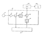
- the Figure appended hereto is an expanded block diagram illustrating a VCR interface provided according to the present invention.
- VCR interface 10 which receives radio frequency (RF) TV signals at input terminal 11.
- An optional RF amplifier 13 can be provided to amplify the incoming broadband RF input signal.
- the RF input is from a conventional cable TV drop between 50 and 550 MHz.
- the input signal carries a plurality of television channels, each with a channel width of approximately 6 MHz.
- the input signal is further characterized by one or more premium channels which are scrambled by techniques known in the art. The scrambling of the signal channels prevents normal viewing with a conventional TV or proper recording with a VCR.
- the VCR interface includes radio frequency signal splitter 12, typically a directional coupler configured as a power tap splitter, which receives the RF input signals and provides two signals therefrom.
- the frequency characteristics of both first and second divided signals provided from the splitter are unchanged from the RF input signal. All the signal channels including the scrambled premium channels are present.
- the first divided signal is provided to a conventional cable TV converter/descrambler 14.
- a converter/descrambler is comprised of a conventional RF tuner for selecting one of the signal channels presented thereto.
- the tuner (not shown) may be selectable by either manual or electronic means.
- the selected TV channel is presented to a conventional descrambler, also not shown, which descrambles the television signal on that channel, if required.
- the signal output from the converter/descrambler is modulated on a pre-defined single channel, typically channel 2, 3 or 4.
- a pre-defined single channel typically channel 2, 3 or 4.
- the tuner in the television is set to receive channels 2, 3 or 4, and channel selection from the incoming TV signal is accomplished using the tuner in the converter/descrambler.
- the second divided signal from the signal splitter isprovided to band reject filter 16 having a bandwidth of one TV channel (6 MHz) approximately centered at the selected signal channel output of the converter/descrambler (channel 2, 3 or 4).
- the band reject filter may be of a type well known in the art and should possess a minimum of approximately 60 dB signal rejection.
- the converter/descrambler output signal (centered at channel 2/3/4) is provided to the VCR interface at bandpass filter 18 which has a pass band of approximately one channel wide (6 MHz) that is selected to be the same as the channel removed by band reject filter 16.
- a VCR interface provided according to the present invention allows the TV subscriber to watch and record separate channels simultaneously in all configurations, independent of the presence or absence of scrambled TV signals.
- the well known limiting effects of the converter/descrambler are eliminated without extraneous converter/descramblers or RF switches.
- the recombined signal presented to the VCR contains the full spectrum of TV channels which comprise the RF input signal, but now includes descrambled premium channel signals.
- VCR tuned to the selected channel (2, 3 or 4)
- all channels can be viewed or recorded, including a premium channel. If the subscriber wishes to view a channel other than the one being recorded he can do so by switching the VCR to the "TV" mode on the "TV/VCR” switch, as was previously possible before the introduction of the converter/descrambler.
- the other operational modes of the VCR are unaffected by a VCR interface provided according to the present invention.
- the subscriber can view a premium channel and simultaneously record a basic (or "clear") channel, watch a basic channel and record a premium channel, as well as watch a basic channel and record another basic channel simultaneously.
- the subscriber can record a channel selected with the internal VCR tuner, monitor the recorded program or view a different channel by proper selection of the "TV/VCR" switch and the TV tuner. Note also that the subscriber is now able to program his VCR to record from different channels. All of these operational modes can be accomplished without any external switching.
- VCR event programming is limited to only one descrambled TV channel. Watching a basic TV channel and recording a premium TV channel requires an additional means for splitting the input signal from the cable TV drop, with one signal path directly to the TV, while signals on the second signal path are presented to the converter/descrambler and subsequently to the VCR to be recorded. All of these complicated configurations and wiring changes are eliminated by the use of a VCR interface provided according to the present invention.
- band pass filter 18 from the VCR interface, as many cable TV converters/descramblers already possess some appropriate band pass filtering means.
- those skilled in the art will also note that it is possible to combine the VCR interface and converter/descramblers to provide an interface/descrambler which would perform all the functions of a VCR interface and converter/descrambler as noted hereinabove, but would be contained in a single compact unit.
- Converter/descramblers used with such a cable TV system would be comprised so that signals output therefrom are provided on the preselected channel.
- a VCR interface in accordance with the present invention and used with such a system can be provided without a notch filtering means, further simplifying construction and reducing cost.
Landscapes
- Engineering & Computer Science (AREA)
- Multimedia (AREA)
- Signal Processing (AREA)
- Two-Way Televisions, Distribution Of Moving Picture Or The Like (AREA)
- Television Signal Processing For Recording (AREA)
Applications Claiming Priority (2)
| Application Number | Priority Date | Filing Date | Title |
|---|---|---|---|
| US87734986A | 1986-06-23 | 1986-06-23 | |
| US877349 | 1986-06-23 |
Publications (2)
| Publication Number | Publication Date |
|---|---|
| EP0252058A2 true EP0252058A2 (de) | 1988-01-07 |
| EP0252058A3 EP0252058A3 (de) | 1988-08-03 |
Family
ID=25369805
Family Applications (1)
| Application Number | Title | Priority Date | Filing Date |
|---|---|---|---|
| EP87870086A Withdrawn EP0252058A3 (de) | 1986-06-23 | 1987-06-18 | Schnittstelle eines Videokassettenrekorders zum Empfangen von Kabelfernsehsignalen |
Country Status (2)
| Country | Link |
|---|---|
| EP (1) | EP0252058A3 (de) |
| JP (1) | JPS634779A (de) |
Family Cites Families (4)
| Publication number | Priority date | Publication date | Assignee | Title |
|---|---|---|---|---|
| US4316217A (en) * | 1979-03-26 | 1982-02-16 | Rifken Jerome C | Method and apparatus for connecting a cable television system to a video cassette recorder |
| CA1203018A (en) * | 1982-02-12 | 1986-04-08 | Daisuke Kozakai | Remote control system |
| JPS60233982A (ja) * | 1984-05-07 | 1985-11-20 | Keihin Kiyuukou Dentetsu Kk | テレビ共聴システムの周波数変換方法 |
| FR2573266A1 (fr) * | 1984-11-09 | 1986-05-16 | Cedelle Paul | Dispositif de decodage d'emissions de television codees, destine notamment a une installation d'antenne collective |
-
1987
- 1987-05-29 JP JP62134737A patent/JPS634779A/ja active Pending
- 1987-06-18 EP EP87870086A patent/EP0252058A3/de not_active Withdrawn
Also Published As
| Publication number | Publication date |
|---|---|
| JPS634779A (ja) | 1988-01-09 |
| EP0252058A3 (de) | 1988-08-03 |
Similar Documents
| Publication | Publication Date | Title |
|---|---|---|
| US5512963A (en) | Apparatus and methods for providing combining multiple video sources | |
| US4864613A (en) | Broadband converter/descrambler interface for cable TV | |
| US6459793B1 (en) | Cable television setback decoder automatic control | |
| US4603349A (en) | Cable television system with stereo sound reproduction | |
| US5796423A (en) | System for integrating digital audio and analog video to provide seamless user transparent features | |
| EP0392552B9 (de) | Tonumschaltung für ein Ton/Videosystem mit S-Videofähigkeit | |
| US4630133A (en) | VCR with total record/view flexibility | |
| US4509210A (en) | Television receiver adaptable for descrambler module | |
| US4771456A (en) | Cable television channel selector/descrambler for use with cable-ready video applicances | |
| EP0684735B1 (de) | Schnittstellenbildung für Rundfunksignale mittels elektronischer Vorrichtungen | |
| JPH0237892A (ja) | Tv信号におけるスクランブルチャンネルをデスクランブルするためのデスクランブラ方式 | |
| US6848116B1 (en) | Method and apparatus for on-demand video program access control using integrated out-of-band signaling for channel selection | |
| US4272791A (en) | Method and apparatus for video recording | |
| US5216499A (en) | Cable select box supplemental signal splitting apparatus | |
| US7102699B2 (en) | Radio frequency distribution network system | |
| US5532733A (en) | Remodulation of a cable box output signal to a UHF channel | |
| EP0252058A2 (de) | Schnittstelle eines Videokassettenrekorders zum Empfangen von Kabelfernsehsignalen | |
| US4109281A (en) | Terminal device for catv | |
| GB2247375A (en) | Domestic audio/visual entertainment system | |
| KR0171362B1 (ko) | 화상 암호해독 기능을 갖는 비디오 카세트 레코드 플레이어 | |
| KR0119482Y1 (ko) | 기록재생장치의 가입자 단말장치 제어회로 | |
| JPH06311470A (ja) | 磁気記録装置 | |
| KR960010429Y1 (ko) | 비디오/오디오 신호출력 선택회로 | |
| JPH0434623Y2 (de) | ||
| JP2947585B2 (ja) | 衛星放送チューナ内蔵のテレビジョン受像機 |
Legal Events
| Date | Code | Title | Description |
|---|---|---|---|
| PUAI | Public reference made under article 153(3) epc to a published international application that has entered the european phase |
Free format text: ORIGINAL CODE: 0009012 |
|
| AK | Designated contracting states |
Kind code of ref document: A2 Designated state(s): BE CH DE ES FR GB IT LI NL SE |
|
| PUAL | Search report despatched |
Free format text: ORIGINAL CODE: 0009013 |
|
| AK | Designated contracting states |
Kind code of ref document: A3 Designated state(s): BE CH DE ES FR GB IT LI NL SE |
|
| STAA | Information on the status of an ep patent application or granted ep patent |
Free format text: STATUS: THE APPLICATION IS DEEMED TO BE WITHDRAWN |
|
| 18D | Application deemed to be withdrawn |
Effective date: 19890204 |
|
| RIN1 | Information on inventor provided before grant (corrected) |
Inventor name: WACHOB, DAVID E. |
|
| P01 | Opt-out of the competence of the unified patent court (upc) registered |
Effective date: 20230522 |