EP0251908B1 - Generator für die Erzeugung von variablen, programmierbaren Frequenzsignalen - Google Patents
Generator für die Erzeugung von variablen, programmierbaren Frequenzsignalen Download PDFInfo
- Publication number
- EP0251908B1 EP0251908B1 EP87401473A EP87401473A EP0251908B1 EP 0251908 B1 EP0251908 B1 EP 0251908B1 EP 87401473 A EP87401473 A EP 87401473A EP 87401473 A EP87401473 A EP 87401473A EP 0251908 B1 EP0251908 B1 EP 0251908B1
- Authority
- EP
- European Patent Office
- Prior art keywords
- frequency
- divider
- division ratio
- value
- instantaneous
- Prior art date
- Legal status (The legal status is an assumption and is not a legal conclusion. Google has not performed a legal analysis and makes no representation as to the accuracy of the status listed.)
- Expired - Lifetime
Links
Images


Classifications
-
- H—ELECTRICITY
- H03—ELECTRONIC CIRCUITRY
- H03B—GENERATION OF OSCILLATIONS, DIRECTLY OR BY FREQUENCY-CHANGING, BY CIRCUITS EMPLOYING ACTIVE ELEMENTS WHICH OPERATE IN A NON-SWITCHING MANNER; GENERATION OF NOISE BY SUCH CIRCUITS
- H03B23/00—Generation of oscillations periodically swept over a predetermined frequency range
-
- H—ELECTRICITY
- H03—ELECTRONIC CIRCUITRY
- H03B—GENERATION OF OSCILLATIONS, DIRECTLY OR BY FREQUENCY-CHANGING, BY CIRCUITS EMPLOYING ACTIVE ELEMENTS WHICH OPERATE IN A NON-SWITCHING MANNER; GENERATION OF NOISE BY SUCH CIRCUITS
- H03B2200/00—Indexing scheme relating to details of oscillators covered by H03B
- H03B2200/006—Functional aspects of oscillators
- H03B2200/0092—Measures to linearise or reduce distortion of oscillator characteristics
Definitions
- the invention relates to a device for generating signals with programmable variable frequency, the law of variation of the frequency being a polynomial law of time.
- the present invention aims to remedy the aforementioned drawbacks by the use of a variable frequency signal generator programmable according to a polynomial time variation law of the type mentioned above with reference to document EP-A- 0 088 669.
- Another object of the present invention is the implementation of a programmable variable frequency signal generator which can generate very high frequency values.
- Another object of the present invention is the implementation of a programmable variable frequency signal generator making it possible to establish a law of variation of continuous frequency as a function of time, the law of variation possibly consisting of a plurality of elementary laws of successive variations.
- Another object of the present invention is also the implementation of a variable frequency signal generator programmable in the form of an integrated circuit, the integrated circuit being capable of constituting a peripheral element of the central unit of a computer, d 'a computer or microcomputer.
- the device for generating variable-frequency signals programmable according to a law of polynomial variation of time, object of the invention is remarkable in that said control chain of the first frequency divider supplied by the reference oscillator comprises, connected in cascade , a second frequency divider with controlled division ratio and a first programmable integrator system, the output of which delivers to the first frequency divider the value of the instantaneous division ratio and in that said device also comprises a chain for controlling the second divider of frequency comprising a second integrator system receiving the output signal and delivering the instantaneous division ratio to said second divider with controlled division ratio, said first and second integrator system integrating in magnitude and in opposite sign of their input signals, said frequency output signal having an instantaneous frequency of the polynomial form in which t represents time from an origin of arbitrary time and Kj the coefficients of each monone of degree j.
- the invention finds application in any system involving frequency synthesis, radio transmission in electromagnetic detection techniques, automatic control of electric motors and in particular robotics, a technique in which the establishment of motor control laws more and more precise and diverse are necessary.
- variable frequency signal generator device programmable according to a polynomial law of time, object of the present invention, will firstly be described in relation to FIG. 1.
- the programmable variable frequency signal generator device makes it possible to obtain a law for varying the frequency FS of the output signal according to a polynomial law of time.
- polynomial law of the time of the frequency FS of the output signal is meant a frequency law of the form in which t represents time from an origin of arbitrary time and Kj the coefficients of each monome of degree j, the coefficients Kj being determined as a function of initialization parameters of the generating device as will be described below in the description.
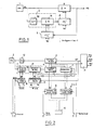
- the generator device comprises a reference oscillator, denoted 1, making it possible to generate a reference signal at arbitrary frequency FHL.
- a first frequency divider, denoted 2, with controlled division ratio N receives the signal of arbitrary frequency of reference FHL and delivers in operation a output signal of instantaneous frequency FS.
- the output signal of the first divider 2 constitutes the output signal of the generator device object of the invention.
- a control chain for the first frequency divider 2 is supplied by the reference oscillator 1 and comprises, connected in cascade, a second frequency divider 3 with controlled division ratio and a first programmable integrator system 4, the output of which delivers to the first frequency divider 2 the value of the instantaneous division ratio N.
- a second control chain of the second frequency divider 3 comprises a second integrator system 5 receiving the instantaneous frequency output signal FS and delivers the instantaneous division ratio to the second divider 3 with controlled division ratio.
- the first 4 and second 5 integrating system present at each instant a transfer function denoted -S ⁇ and + S ⁇ or vice versa as noted in FIG. 1.
- the first 4 and the second 5 integrating system are capable of enabling the origin of the time parameter t an initialization of the division ratios N and B of the first and second frequency dividers 2, 3 to the values No and Bo respectively.
- the reference oscillator 1 can be constituted by a pulse generator with fixed recurrence frequency controlled by quartz.
- the first 3 and second 5 integrator systems can then be constituted by pulse counter-up-counter devices.
- the first 2 and second 3 frequency dividers with controlled division ratio can be constituted by programmable delay circuits and, advantageously, by controlled binary logic circuits ensuring as a function of their respective instantaneous division ratio N, B, the corresponding division of the number of pulses of their input signal, as will be explained in more detail later in the description.
- the second divider 3 comprises, connected in cascade, a first frequency divider 30 with adjustable division ratio A, independently of the second control chain and a second frequency divider 31 with division ratio controlled by the second chain of the control constituted by the second integrator system.
- the reference oscillator 1 generates pulses at the reference recurrence frequency FHL.
- the second frequency divider 3, consisting of the two cascaded dividers 30 and 31 delivers an instantaneous frequency signal at its output relation in which B represents the instantaneous value of the division ratio of the divider 31.
- the first integrating system 4 consisting of an integrating counter as described above makes it possible to count or count down the pulses received as a function of the value of the sign parameter S.
- the first integrating system 4 delivers the instantaneous value of the division ratio N to the first divisor 2.
- the second integrating system 5 also performs as a function of the value of the parameter of sign S a negative or positive integration of the pulses from an initial value Bo. It therefore performs a countdown or a counting of the pulses constituted by the frequency output signal FS and delivers the instantaneous value of the division ratio B to the second divider 3, more particularly to the programmable divider 31.
- B S ⁇ FSdt
- the signal delivered by the second divider 3 and more particularly by the divider 31 is written:
- the division ratio N of the first divider 2 is written: and the frequency FS of the output signal is written For a frequency FS of the form
- the frequency FS of the output signal is indeed an instantaneous frequency of the form as a function of the value of the parameters A, Bo, No of the generator device which is the subject of the invention.
- the generator device as described in FIG. 1 and in FIG. 2 makes it possible in fact to obtain a variation of the frequency FS of the output signal according to discrete values, the law of variation being materialized by a succession of points constituted in fact by the pulses delivered by the first divider 2, the instantaneous frequency FS of the output signal being defined as the inverse of the time which separates two consecutive pulses or points.
- the first frequency divider 2 is a programmed generator of space between points: at each point or pulse delivered by the reference oscillator 1, it takes into account the instantaneous value N of the division ratio and waits for N pulses generated by the reference oscillator 1 to generate the next pulse constituting the signal FS frequency output.
- the points FSi of the curve or law of variation of the output frequency FS are defined in the following manner, as a function of each instant ti where Ni represents the value of the division ratio N at time i of the first divisor 2, and the slope Pi of curve or law of variation at time ti is written:
- the first and second dividers are initialized to the values No, A, Bo and the value of S is fixed.
- ⁇ i represents the frequency attenuation for the final pulse of order i and at time ti + 1.
- each instant of order i + 1 checks the relation: ⁇ i representing the discretized image of the time integral.
- the first frequency divider 30 can be constituted by a frequency divider with adjustable division ratio, the value of the division ratio A being controlled from an external control . It is thus possible to modify the value of the division ratio A during operation, which has the effect of modifying, at the point considered, the radius of curvature of the law of frequency variation according to a polynomial law of time at the point considered .
- Modifying the value of parameter A for example at a point of order i makes it possible to obtain two values of different slopes, for example: The report is little different from A2 A1 , this having the consequence that there is an angular point all the more marked as the A2 / A1 ratio is large.
- a first solution can consist in preserving at each point of order i - 1, i a product A x ⁇ i substantially constant.
- the constancy of the product A x ⁇ i can be obtained by temporary local modification of the value of the division ratio B of the integrating system 5.
- the change in slope in the absence of an angular point can preferably be obtained by means of a control of the division ratio A by an external circuit constituted for example by an integrating circuit.
- the integrator circuit noted 6 is constituted by an integrator counter.
- N fictitious point N ⁇ o
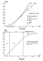
- the value of K is: and the table gives the value of the reducing coefficient R:
- This reducing coefficient is all the more effective when n is large.
- the advantage of the reducing coefficient is to be able to decrease the value of K when it is no longer possible to increase the initial value No due to the maximum capacity of the meters. For a given value No, we have a network of curves which pass through a fixed point of frequency
- the direction of travel of the curve that is to say the variation of the frequency of the output signal FS, is determined by the sign of S.
- the only fact, at a determined instant, to reverse the sign of S has the effect of reversing the direction of travel and the variation of the frequency FS of the output signal.
- the oscillator 1 can advantageously be constituted by a 2 MHz pulse generator oscillator of the CEPE OM 16 series, the first divider 2 by a 16-bit divider for example and the second divider 3 can be constituted by a first adjustable gain divider 2A, 30, followed by 16-bit divider.
- the first and the second integrating counter 4, 5, can likewise consist of a 16-bit counter.
- a 4-bit counter 6 makes it possible to adjust the adjustable divider 30.
- An auxiliary divider 12, divider by two for example, makes it possible in connection with the adjustable divider 30 to obtain a report of the corresponding division ratios in non-integer values.
- the device which is the subject of the invention can also advantageously include a comparison loop of the value of the instantaneous frequency FS of the output signal, digital comparator 7, with a threshold value delivered by a programmable setpoint generator 8.
- the initial value No of the first integrator 4 is delivered by a programmable digital setpoint generator 9.
- the setpoint 8 and initial value 9 generators can be programmed from encoder wheels 10 or from any other means. In particular, a microcomputer can be used.
- the comparison loop allows, on positive comparison of the value of the instantaneous frequency FS, with the threshold or setpoint value, a reset of the system.
- the frequency output FS can be connected to a sinusoidal generator circuit 11, three-phase for example, for use for controlling synchronous motors .
- FIG 3a there is shown a diagram of a generator device in accordance with the object of the invention more specially adapted for use for controlling a motor such as a synchronous motor.
- the generator device comprises in this case, in addition to the elements of FIG. 2, a series of buffer memories 13, 14 interconnected by a link of the BUS type, data bus, to a microcomputer for example.
- the reference generators 9, 8 and the 4-bit counter 6 can be replaced by buffer memories interconnected with the data BUS.
- the various setpoint or control values are then stored in the corresponding buffer memories.
- the memory 6 stores the value 2A which makes it possible to choose the power of t or degree of the polynomial.
- This value can be modified during operation, for example to start with linearly increasing acceleration then operation at constant acceleration.
- the memory 13 stores the initial value Bo, the memory 9 the value No and the memory 8 the frequency FS or setpoint value to be reached, which is analyzed by the speed to be reached by the motor. This setpoint can be changed at any time.
- the memory 14 stores the control commands by all or nothing, such as blocking of the device by value of the output D1, the first 4 and second 5 integrators being initialized. For the complemented value of D1, D1 the device is released and the output frequency FS changes to the frequency and the final value is determined by the setpoint C.
- Circuit 15 allows addressing of the various memories.
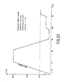
- a synchronous motor control is shown with speed increase according to an S curve.
- the abscissa axis is graduated in units of time, in seconds, and the ordinate axis in number of revolutions per second.
- the generator part of the device is identical to the diagram in Figure 1.
- the device comprises in addition, connected at the output of the first frequency divider 2 with controlled division ratio, a bistable type circuit 40 making it possible to generate from the output signal at frequency FS a rectangular signal for example of the same instantaneous frequency.
- a harmonic frequency filter 41 is slaved to the fundamental frequency of the rectangular signal and makes it possible to deliver a signal whose frequency corresponds to the first harmonic of the rectangular signal.
- the generator device object of the invention, can advantageously find application to frequency generator circuits for frequency-agile radars, to coded emission transmission systems.
- the terminal circuits can be produced in TTLS or ECL technology for example.
- FIGS. 5a and 5b Another advantageous embodiment of a generator device according to the invention will be described in connection with FIGS. 5a and 5b in the case of the control of stepping motors.
- a speed control template is used, template as shown in Figure 5b for example.
- the generator device according to the present invention comprises substantially the same elements as the generator device shown in FIG. 3a, for example as regards elements 13, 11, 9, 8, 14 and 15.
- the setpoint for the number of steps is stored in the buffer memory 18 and a total step counter 17 is initialized at start-up with this number of steps, like the buffer memory 18.
- the direction of rotation of the motor is controlled by a command all or nothing D3 delivered by memory 14, the command acting directly at a switching circuit 50 delivering a corresponding signal I+, I ⁇ .
- the frequency output FS is halved.
- a stable frequency step counter 16 is further provided. Thanks to the two counters 16 and 17 and to the buffer 18 which stores the setpoint P, the template is correctly described. At initialization, the counters 16 and 17 are loaded with the value P.
- the discrete variable D1 stored at 14 arms the flip-flop 19 which unlocks the system.
- the FS output frequency increases according to the programmed slope No, the counters 16, 17 count down from their initial value the pulses seen in FS.
- the comparator 7 indicates equality and arms the flip-flop 20 which blocks the counter 16.
- the counter 17 continues to count the pulses until it goes to zero, this point corresponding to a point symmetry of the template.
- the counter 17 is then reloaded with the setpoint P, the flip-flop 20 is disarmed, the counter 16 is released, its content representing the number of pulses remaining at constant frequency.
- the sign of S is reversed and the frequency begins to decrease according to the programmed slope.
- the flip-flop 19 is disarmed and the system is blocked until a new command.
- the discrete variable D2 allows you to place yourself in speed control.
- a high performance variable frequency signal generator device has thus been described, the variety of applications of which is of great interest.
- the described embodiment of the device according to the invention in wired logic is in no way limiting.
- the generator device can very advantageously be produced in the form of an integrated circuit, at least as regards the generator part proper.
- the integrated circuit can advantageously be arranged so that it constitutes a peripheral circuit of microprocessor or of the central unit of a microcomputer.
Landscapes
- Stabilization Of Oscillater, Synchronisation, Frequency Synthesizers (AREA)
Claims (14)
- Generator für die Erzeugung von variablen, programmierbaren Frequenzsignalen gemäß einem Polynom-Änderungsgesetz der Zeit mit:
- einem Bezugsoszillator (1), der das Erzeugen eines Bezugssignales (FHL) mit beliebiger Frequenz erlaubt,- einem ersten Frequenzteiler (2) für gesteuerte Division (N), wobei der erste Frequenzteiler (2) das Bezugssignal (FHL) mit beliebiger Frequenz empfängt und im Betrieb ein Ausgangssignal (FS) mit Momentanfrequenz abgibt,- eine vom Bezugsoszillator (1) versorgte Steuerkette des ersten Frequenzteilers,
dadurch gekennzeichnet, daß die Steuerkette des ersten Frequenzteilers in Kaskadenschaltung einen zweiten Frequenzteiler (3) für gesteuerte Division und eine erste programmierbare Integriereinheit (4) aufweist, deren Ausgang an den ersten Frequenzteiler (2) den momentanen Wert für Division N liefert, und daß der Generator außerdem aufweist:
- eine Steuerkette des zweiten Frequenzteilers (3) mit einer zweiten Integriereinheit (5), die das Ausgangssignal (FS) empfängt und den momentanen Divisionswert an den zweiten Frequenzteiler (3) für gesteuerte Division abgibt, wobei die erste (4) und die zweite (5) Integriereinheit eine Integration in Größe und Vorzeichen (S) entgegengesetzt zu ihren Eingangssignalen bewirken und das Ausgangssignal (FS) eine Momentanfrequenz der Polynomform
- Generator nach Anspruch 1, dadurch gekennzeichnet, daß der Bezugsoszillator (1) ein quarzgesteuerter Impulsgenerator für Impulse fester Wiederholfrequenz ist.
- Generator nach Anspruch 1 oder 2, dadurch gekennzeichnet, daß die erste und die zweite Integiereinheit aus Impuls-Zählern/Abwärtszählern bestehen.
- Generator nach einem der Ansprüche 1 bis 3, dadurch gekennzeichnet, daß die Frequenzteiler (2, 3) für gesteuerte Division aus programmierbaren Verzögerungsschaltungen bestehen.
- Generator nach einem der Ansprüche 1 bis 3, dadurch gekennzeichnet, daß die Frequenzteiler (2, 3) für gesteuerte Division aus gesteuerten binären Logikschaltungen bestehen.
- Generator nach Anspruch 2 oder 3, dadurch gekennzeichnet, daß der zweite Frequenzteiler (3) in Kaskadenschaltung einen ersten Frequenzteiler (30) für einstellbare (A) bestimmte Division und einen zweiten Frequenzteiler (31) für gesteuerte Division (B) aufweist.
- Generator nach einem der Ansprüche 2 bis 6, dadurch gekennzeichnet, daß die momentane Frequenz (FS) des Ausgangssignales als Inverse der Zeit festgelegt ist, welche zwei Impulse trennt, die durch den ersten Frequenzteiler (2) geliefert sind.
- Generator nach den Ansprüchen 6 und 7, dadurch gekennzeichnet, daß der erste Frequenzteiler (30) für einstellbare Division (A) ein programmierbarer Teiler ist, der durch eine Integrierschaltung ausgehend von einem Bezugswert steuerbar ist, wobei die Steuerung des Wertes für die Division A das Durchführen einer kontinuierlichen Änderung des Polynom-Änderungsgesetzes der Frequenz abhängig von der Zeit erlaubt.
- Generator nach einem der Ansprüche 1 bis 8, dadurch gekennzeichnet, daß die ersten und zweiten Integriereinheiten (4, 5), die eine Integration in Größe und Vorzeichen (S) von ihren Eingangssignalen durchführen, abhängig von der Wahl des Vorzeichens (S) eine Abweichung des Polynom-Änderungsgesetzes der Ausgangsfrequenz (FS) um Werte erlauben, die zeitabhängig mit der Frequenz zunehmen bzw. abnehmen.
- Generator nach einem der Ansprüche 1 bis 9, dadurch gekennzeichnet, daß er außerdem eine Vergleichsschleife für den Wert der Momentanfrequenz (FS) des Ausgangssignales mit einem programmierbaren Schwellenwert aufweist, wobei das Vergleichsband durch positiven Vergleich des Wertes der Momentanfrequenz (FS) mit dem Schwellenwert eine erneute Auslösung des Systems erlaubt.
- Generator nach einem der Ansprüche 1 bis 10, dadurch gekennzeichnet, daß im Hinblick auf das Erzeugen einer Sinus-Wellenform mit einer Frequenz, die gemäß einem Polynom-Änderungsgesetz der Zeit variabel ist, der Generator außerdem am Ausgang des ersten Frequenzteilers (2) für gesteuerte Division eine bistabile Schaltung, die aus dem genannten Ausgangssignal der Frequenz (FS) ein Rechtecksignal der gleichen Momentanfrequenz zu erzeugen vermag, und ein Filter harmonischer Frequenz, das auf die Grundfrequenz des Rechtecksignales eingestellt ist, aufweist.
- Generator nach einem der vorangehenden Ansprüche, dadurch gekennzeichnet, daß er in der Form einer integrierten Schaltung realisiert ist.
- Verwendung eines Generators für variable programmierbare Frequenzsignale nach einem der Ansprüche 1 bis 12 für die Steuerung von Motoren, dadurch gekennzeichnet, daß die Steuerparameter in Hilfsspeichern abgespeichert sind, die über eine Bus-Verbindung mit einem Rechneranschluß oder einem Mikrorechner verbunden sind.
- Verwendung nach Anspruch 13, dadurch gekennzeichnet, daß im Hinblick auf die Steuerung von Schrittmotoren eine Steuerlehre für die Motordrehzahl verwendet wird, wobei die Lehre das Zählen aller bewirkten Schritte, das Zählen der Schritte mit maximaler Frequenz in Betrieb nimmt und der Befehl für Anwachsen und Abnehmen der Motor-Drehzahl durch Änderung des Vorzeichens der Integriereinheiten (4, 5) bewirkt wird.
Applications Claiming Priority (2)
| Application Number | Priority Date | Filing Date | Title |
|---|---|---|---|
| FR8609193A FR2600847B1 (fr) | 1986-06-25 | 1986-06-25 | Dispositif generateur de signaux a frequence variable programmable |
| FR8609193 | 1986-06-25 |
Publications (2)
| Publication Number | Publication Date |
|---|---|
| EP0251908A1 EP0251908A1 (de) | 1988-01-07 |
| EP0251908B1 true EP0251908B1 (de) | 1991-10-30 |
Family
ID=9336695
Family Applications (1)
| Application Number | Title | Priority Date | Filing Date |
|---|---|---|---|
| EP87401473A Expired - Lifetime EP0251908B1 (de) | 1986-06-25 | 1987-06-25 | Generator für die Erzeugung von variablen, programmierbaren Frequenzsignalen |
Country Status (4)
| Country | Link |
|---|---|
| US (1) | US4870366A (de) |
| EP (1) | EP0251908B1 (de) |
| DE (1) | DE3774193D1 (de) |
| FR (1) | FR2600847B1 (de) |
Families Citing this family (7)
| Publication number | Priority date | Publication date | Assignee | Title |
|---|---|---|---|---|
| DE3826006C1 (de) * | 1988-07-30 | 1989-10-12 | Wandel & Goltermann Gmbh & Co, 7412 Eningen, De | |
| US5095280A (en) * | 1990-11-26 | 1992-03-10 | Integrated Circuit Systems, Inc. | Dual dot clock signal generator |
| US5650738A (en) * | 1995-12-21 | 1997-07-22 | Hughes Aircraft Company | Precision digital phase shift element |
| US5703514A (en) * | 1995-12-21 | 1997-12-30 | Hughes Electronics | Digital frequency divider phase shifter |
| RU2168848C2 (ru) * | 1999-08-27 | 2001-06-10 | Российский Федеральный Ядерный Центр - Всероссийский Научно-Исследовательский Институт Экспериментальной Физики | Генератор фрактального сигнала |
| US7304288B2 (en) * | 2005-07-06 | 2007-12-04 | The United States Of America As Represented By The Secretary Of The Navy | Laser pulse counter |
| TWI369879B (en) * | 2007-06-06 | 2012-08-01 | Qisda Corp | Method and apparatus for adjusting reference frequency |
Family Cites Families (8)
| Publication number | Priority date | Publication date | Assignee | Title |
|---|---|---|---|---|
| US3566096A (en) * | 1966-07-25 | 1971-02-23 | Pacific Ind Inc | Digital ratiometer |
| US3548320A (en) * | 1968-05-23 | 1970-12-15 | Us Navy | Digital fm sweep generator |
| SU596954A1 (ru) * | 1975-05-26 | 1978-03-05 | Ордена Трудового Красного Знамени Институт Радиотехники И Электроники Ан Ссср | Устройство дл формировани сигналов с изменением частоты по закону полинома п-ой степени |
| US4103216A (en) * | 1976-05-28 | 1978-07-25 | Tally Corporation | Stepping motor closed loop constant velocity control system |
| JPS5485091A (en) * | 1977-12-20 | 1979-07-06 | Hitachi Ltd | Frequency sweeping circuit |
| FR2522826B1 (fr) * | 1982-03-05 | 1986-01-31 | Thomson Csf | Dispositif de generation numerique d'un signal module en frequence et dispositif radiofrequence comprenant un tel dispositif numerique |
| US4450532A (en) * | 1982-04-19 | 1984-05-22 | General Electric Company | Voltage to frequency converter |
| FR2576470B1 (fr) * | 1985-01-22 | 1989-05-26 | Veglia | Convertisseur frequence-frequence a sortie variable |
-
1986
- 1986-06-25 FR FR8609193A patent/FR2600847B1/fr not_active Expired
-
1987
- 1987-06-23 US US07/065,560 patent/US4870366A/en not_active Expired - Fee Related
- 1987-06-25 EP EP87401473A patent/EP0251908B1/de not_active Expired - Lifetime
- 1987-06-25 DE DE8787401473T patent/DE3774193D1/de not_active Expired - Lifetime
Also Published As
| Publication number | Publication date |
|---|---|
| EP0251908A1 (de) | 1988-01-07 |
| FR2600847A1 (fr) | 1987-12-31 |
| FR2600847B1 (fr) | 1988-10-21 |
| US4870366A (en) | 1989-09-26 |
| DE3774193D1 (de) | 1991-12-05 |
Similar Documents
| Publication | Publication Date | Title |
|---|---|---|
| EP0251908B1 (de) | Generator für die Erzeugung von variablen, programmierbaren Frequenzsignalen | |
| EP0142440A2 (de) | Vorrichtung zum Erzeugen einer, bezüglich einer Referenzfrequenz gebrochenen Frequenz | |
| EP0199613B1 (de) | Verfahren und Vorrichtung zur Beschleunigungsregelung eines elektrischen Schrittmotors | |
| FR2487142A1 (fr) | Circuit et procede de conversion a/n ou n/a de signaux bipolaires utilisant une unique tension de reference | |
| EP0586696B1 (de) | Steuereinrichtung zur Positionierung eines Objektes in eine Soll-Lage | |
| FR2695211A1 (fr) | Dispositif et procédé d'analyse de signaux ILS. | |
| EP0207859B1 (de) | Rechnungseinrichtung zur diskreten und verschiebenden Fourier-Transformation zur Verwendung in einem Radarsystem | |
| EP0022695B1 (de) | Geschaltete Filtereinheit | |
| EP0049652A1 (de) | Einrichtung zur zeitlichen Kompression und Einrichtung zur zeitlichen Dekompression von Daten | |
| EP2978127A1 (de) | Verfahren zur digitalen kompensation von variationen, abhängig von der temperatur, einer elektrischen grösse einer integrierten weltraum-funktelekommunikationsausrüstung | |
| EP0591813B1 (de) | Phasenkontinuierlicher Modulator | |
| EP1887750A1 (de) | FSK Modulationsvorrichtung | |
| EP0075376B1 (de) | Handhabungsverfahren der Frequenzsteuerungen eines Senders-Empfängers und der Programmierung des programmierbaren Zählers seines digitalen Frequenzsynthesierers | |
| CH675937A5 (de) | ||
| EP1253512B1 (de) | Verfahren und Vorrichtung zur Erzeugung eines Zufallssignals mit kontrolliertem Histogramm und Spektrum | |
| CA1244920A (fr) | Procede d'extension de la gamme des frequences des recurrences radar acceptables par un transformateur numerique d'images et moyens de mise en oeuvre de ce procede | |
| EP3048730A1 (de) | Vorrichtung zur erzeugung einer rückkopplungsschleifenfrequenz | |
| FR2624283A1 (fr) | Circuit integre de calcul numerique pour calculs glissants du type convolution | |
| EP0621682B1 (de) | Einrichtung zur Frequenzteilung | |
| FR2566132A1 (fr) | Procede et dispositif pour la mesure de la periode d'un signal pseudosinusoidal et leurs applications | |
| EP0064902A1 (de) | Digitale Filter | |
| EP0585454B1 (de) | Vorrichtung zum auf und abzaehlen | |
| FR2755552A1 (fr) | Dispositif de recopie d'un signal d'horloge d'entree a frequence non continue | |
| EP0645892A1 (de) | Frequenzregelkreis | |
| FR2576470A1 (fr) | Convertisseur frequence-frequence a sortie variable |
Legal Events
| Date | Code | Title | Description |
|---|---|---|---|
| PUAI | Public reference made under article 153(3) epc to a published international application that has entered the european phase |
Free format text: ORIGINAL CODE: 0009012 |
|
| AK | Designated contracting states |
Kind code of ref document: A1 Designated state(s): DE FR GB IT NL SE |
|
| 17P | Request for examination filed |
Effective date: 19880328 |
|
| 17Q | First examination report despatched |
Effective date: 19900713 |
|
| GRAA | (expected) grant |
Free format text: ORIGINAL CODE: 0009210 |
|
| AK | Designated contracting states |
Kind code of ref document: B1 Designated state(s): DE FR GB IT NL SE |
|
| GBT | Gb: translation of ep patent filed (gb section 77(6)(a)/1977) | ||
| REF | Corresponds to: |
Ref document number: 3774193 Country of ref document: DE Date of ref document: 19911205 |
|
| ITF | It: translation for a ep patent filed | ||
| PGFP | Annual fee paid to national office [announced via postgrant information from national office to epo] |
Ref country code: NL Payment date: 19920630 Year of fee payment: 6 |
|
| PLBE | No opposition filed within time limit |
Free format text: ORIGINAL CODE: 0009261 |
|
| STAA | Information on the status of an ep patent application or granted ep patent |
Free format text: STATUS: NO OPPOSITION FILED WITHIN TIME LIMIT |
|
| 26N | No opposition filed | ||
| PG25 | Lapsed in a contracting state [announced via postgrant information from national office to epo] |
Ref country code: NL Effective date: 19940101 |
|
| NLV4 | Nl: lapsed or anulled due to non-payment of the annual fee | ||
| EAL | Se: european patent in force in sweden |
Ref document number: 87401473.1 |
|
| PGFP | Annual fee paid to national office [announced via postgrant information from national office to epo] |
Ref country code: FR Payment date: 19980427 Year of fee payment: 12 |
|
| PGFP | Annual fee paid to national office [announced via postgrant information from national office to epo] |
Ref country code: SE Payment date: 19980617 Year of fee payment: 12 Ref country code: DE Payment date: 19980617 Year of fee payment: 12 |
|
| PGFP | Annual fee paid to national office [announced via postgrant information from national office to epo] |
Ref country code: GB Payment date: 19980619 Year of fee payment: 12 |
|
| PG25 | Lapsed in a contracting state [announced via postgrant information from national office to epo] |
Ref country code: GB Free format text: LAPSE BECAUSE OF NON-PAYMENT OF DUE FEES Effective date: 19990625 |
|
| PG25 | Lapsed in a contracting state [announced via postgrant information from national office to epo] |
Ref country code: SE Free format text: THE PATENT HAS BEEN ANNULLED BY A DECISION OF A NATIONAL AUTHORITY Effective date: 19990629 |
|
| PG25 | Lapsed in a contracting state [announced via postgrant information from national office to epo] |
Ref country code: FR Free format text: THE PATENT HAS BEEN ANNULLED BY A DECISION OF A NATIONAL AUTHORITY Effective date: 19990630 |
|
| GBPC | Gb: european patent ceased through non-payment of renewal fee |
Effective date: 19990625 |
|
| EUG | Se: european patent has lapsed |
Ref document number: 87401473.1 |
|
| PG25 | Lapsed in a contracting state [announced via postgrant information from national office to epo] |
Ref country code: DE Free format text: LAPSE BECAUSE OF NON-PAYMENT OF DUE FEES Effective date: 20000503 |
|
| REG | Reference to a national code |
Ref country code: FR Ref legal event code: ST |
|
| PG25 | Lapsed in a contracting state [announced via postgrant information from national office to epo] |
Ref country code: IT Free format text: LAPSE BECAUSE OF NON-PAYMENT OF DUE FEES;WARNING: LAPSES OF ITALIAN PATENTS WITH EFFECTIVE DATE BEFORE 2007 MAY HAVE OCCURRED AT ANY TIME BEFORE 2007. THE CORRECT EFFECTIVE DATE MAY BE DIFFERENT FROM THE ONE RECORDED. Effective date: 20050625 |