EP0251908B1 - Programmable variable-frequency signal generator - Google Patents
Programmable variable-frequency signal generator Download PDFInfo
- Publication number
- EP0251908B1 EP0251908B1 EP87401473A EP87401473A EP0251908B1 EP 0251908 B1 EP0251908 B1 EP 0251908B1 EP 87401473 A EP87401473 A EP 87401473A EP 87401473 A EP87401473 A EP 87401473A EP 0251908 B1 EP0251908 B1 EP 0251908B1
- Authority
- EP
- European Patent Office
- Prior art keywords
- frequency
- divider
- division ratio
- value
- instantaneous
- Prior art date
- Legal status (The legal status is an assumption and is not a legal conclusion. Google has not performed a legal analysis and makes no representation as to the accuracy of the status listed.)
- Expired - Lifetime
Links
Images


Classifications
-
- H—ELECTRICITY
- H03—ELECTRONIC CIRCUITRY
- H03B—GENERATION OF OSCILLATIONS, DIRECTLY OR BY FREQUENCY-CHANGING, BY CIRCUITS EMPLOYING ACTIVE ELEMENTS WHICH OPERATE IN A NON-SWITCHING MANNER; GENERATION OF NOISE BY SUCH CIRCUITS
- H03B23/00—Generation of oscillations periodically swept over a predetermined frequency range
-
- H—ELECTRICITY
- H03—ELECTRONIC CIRCUITRY
- H03B—GENERATION OF OSCILLATIONS, DIRECTLY OR BY FREQUENCY-CHANGING, BY CIRCUITS EMPLOYING ACTIVE ELEMENTS WHICH OPERATE IN A NON-SWITCHING MANNER; GENERATION OF NOISE BY SUCH CIRCUITS
- H03B2200/00—Indexing scheme relating to details of oscillators covered by H03B
- H03B2200/006—Functional aspects of oscillators
- H03B2200/0092—Measures to linearise or reduce distortion of oscillator characteristics
Definitions
- the invention relates to a device for generating signals with programmable variable frequency, the law of variation of the frequency being a polynomial law of time.
- the present invention aims to remedy the aforementioned drawbacks by the use of a variable frequency signal generator programmable according to a polynomial time variation law of the type mentioned above with reference to document EP-A- 0 088 669.
- Another object of the present invention is the implementation of a programmable variable frequency signal generator which can generate very high frequency values.
- Another object of the present invention is the implementation of a programmable variable frequency signal generator making it possible to establish a law of variation of continuous frequency as a function of time, the law of variation possibly consisting of a plurality of elementary laws of successive variations.
- Another object of the present invention is also the implementation of a variable frequency signal generator programmable in the form of an integrated circuit, the integrated circuit being capable of constituting a peripheral element of the central unit of a computer, d 'a computer or microcomputer.
- the device for generating variable-frequency signals programmable according to a law of polynomial variation of time, object of the invention is remarkable in that said control chain of the first frequency divider supplied by the reference oscillator comprises, connected in cascade , a second frequency divider with controlled division ratio and a first programmable integrator system, the output of which delivers to the first frequency divider the value of the instantaneous division ratio and in that said device also comprises a chain for controlling the second divider of frequency comprising a second integrator system receiving the output signal and delivering the instantaneous division ratio to said second divider with controlled division ratio, said first and second integrator system integrating in magnitude and in opposite sign of their input signals, said frequency output signal having an instantaneous frequency of the polynomial form in which t represents time from an origin of arbitrary time and Kj the coefficients of each monone of degree j.
- the invention finds application in any system involving frequency synthesis, radio transmission in electromagnetic detection techniques, automatic control of electric motors and in particular robotics, a technique in which the establishment of motor control laws more and more precise and diverse are necessary.
- variable frequency signal generator device programmable according to a polynomial law of time, object of the present invention, will firstly be described in relation to FIG. 1.
- the programmable variable frequency signal generator device makes it possible to obtain a law for varying the frequency FS of the output signal according to a polynomial law of time.
- polynomial law of the time of the frequency FS of the output signal is meant a frequency law of the form in which t represents time from an origin of arbitrary time and Kj the coefficients of each monome of degree j, the coefficients Kj being determined as a function of initialization parameters of the generating device as will be described below in the description.
- the generator device comprises a reference oscillator, denoted 1, making it possible to generate a reference signal at arbitrary frequency FHL.
- a first frequency divider, denoted 2, with controlled division ratio N receives the signal of arbitrary frequency of reference FHL and delivers in operation a output signal of instantaneous frequency FS.
- the output signal of the first divider 2 constitutes the output signal of the generator device object of the invention.
- a control chain for the first frequency divider 2 is supplied by the reference oscillator 1 and comprises, connected in cascade, a second frequency divider 3 with controlled division ratio and a first programmable integrator system 4, the output of which delivers to the first frequency divider 2 the value of the instantaneous division ratio N.
- a second control chain of the second frequency divider 3 comprises a second integrator system 5 receiving the instantaneous frequency output signal FS and delivers the instantaneous division ratio to the second divider 3 with controlled division ratio.
- the first 4 and second 5 integrating system present at each instant a transfer function denoted -S ⁇ and + S ⁇ or vice versa as noted in FIG. 1.
- the first 4 and the second 5 integrating system are capable of enabling the origin of the time parameter t an initialization of the division ratios N and B of the first and second frequency dividers 2, 3 to the values No and Bo respectively.
- the reference oscillator 1 can be constituted by a pulse generator with fixed recurrence frequency controlled by quartz.
- the first 3 and second 5 integrator systems can then be constituted by pulse counter-up-counter devices.
- the first 2 and second 3 frequency dividers with controlled division ratio can be constituted by programmable delay circuits and, advantageously, by controlled binary logic circuits ensuring as a function of their respective instantaneous division ratio N, B, the corresponding division of the number of pulses of their input signal, as will be explained in more detail later in the description.
- the second divider 3 comprises, connected in cascade, a first frequency divider 30 with adjustable division ratio A, independently of the second control chain and a second frequency divider 31 with division ratio controlled by the second chain of the control constituted by the second integrator system.
- the reference oscillator 1 generates pulses at the reference recurrence frequency FHL.
- the second frequency divider 3, consisting of the two cascaded dividers 30 and 31 delivers an instantaneous frequency signal at its output relation in which B represents the instantaneous value of the division ratio of the divider 31.
- the first integrating system 4 consisting of an integrating counter as described above makes it possible to count or count down the pulses received as a function of the value of the sign parameter S.
- the first integrating system 4 delivers the instantaneous value of the division ratio N to the first divisor 2.
- the second integrating system 5 also performs as a function of the value of the parameter of sign S a negative or positive integration of the pulses from an initial value Bo. It therefore performs a countdown or a counting of the pulses constituted by the frequency output signal FS and delivers the instantaneous value of the division ratio B to the second divider 3, more particularly to the programmable divider 31.
- B S ⁇ FSdt
- the signal delivered by the second divider 3 and more particularly by the divider 31 is written:
- the division ratio N of the first divider 2 is written: and the frequency FS of the output signal is written For a frequency FS of the form
- the frequency FS of the output signal is indeed an instantaneous frequency of the form as a function of the value of the parameters A, Bo, No of the generator device which is the subject of the invention.
- the generator device as described in FIG. 1 and in FIG. 2 makes it possible in fact to obtain a variation of the frequency FS of the output signal according to discrete values, the law of variation being materialized by a succession of points constituted in fact by the pulses delivered by the first divider 2, the instantaneous frequency FS of the output signal being defined as the inverse of the time which separates two consecutive pulses or points.
- the first frequency divider 2 is a programmed generator of space between points: at each point or pulse delivered by the reference oscillator 1, it takes into account the instantaneous value N of the division ratio and waits for N pulses generated by the reference oscillator 1 to generate the next pulse constituting the signal FS frequency output.
- the points FSi of the curve or law of variation of the output frequency FS are defined in the following manner, as a function of each instant ti where Ni represents the value of the division ratio N at time i of the first divisor 2, and the slope Pi of curve or law of variation at time ti is written:
- the first and second dividers are initialized to the values No, A, Bo and the value of S is fixed.
- ⁇ i represents the frequency attenuation for the final pulse of order i and at time ti + 1.
- each instant of order i + 1 checks the relation: ⁇ i representing the discretized image of the time integral.
- the first frequency divider 30 can be constituted by a frequency divider with adjustable division ratio, the value of the division ratio A being controlled from an external control . It is thus possible to modify the value of the division ratio A during operation, which has the effect of modifying, at the point considered, the radius of curvature of the law of frequency variation according to a polynomial law of time at the point considered .
- Modifying the value of parameter A for example at a point of order i makes it possible to obtain two values of different slopes, for example: The report is little different from A2 A1 , this having the consequence that there is an angular point all the more marked as the A2 / A1 ratio is large.
- a first solution can consist in preserving at each point of order i - 1, i a product A x ⁇ i substantially constant.
- the constancy of the product A x ⁇ i can be obtained by temporary local modification of the value of the division ratio B of the integrating system 5.
- the change in slope in the absence of an angular point can preferably be obtained by means of a control of the division ratio A by an external circuit constituted for example by an integrating circuit.
- the integrator circuit noted 6 is constituted by an integrator counter.
- N fictitious point N ⁇ o
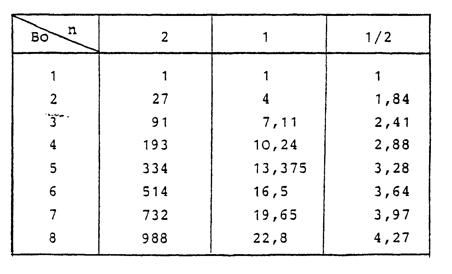
- the value of K is: and the table gives the value of the reducing coefficient R:
- This reducing coefficient is all the more effective when n is large.
- the advantage of the reducing coefficient is to be able to decrease the value of K when it is no longer possible to increase the initial value No due to the maximum capacity of the meters. For a given value No, we have a network of curves which pass through a fixed point of frequency
- the direction of travel of the curve that is to say the variation of the frequency of the output signal FS, is determined by the sign of S.
- the only fact, at a determined instant, to reverse the sign of S has the effect of reversing the direction of travel and the variation of the frequency FS of the output signal.
- the oscillator 1 can advantageously be constituted by a 2 MHz pulse generator oscillator of the CEPE OM 16 series, the first divider 2 by a 16-bit divider for example and the second divider 3 can be constituted by a first adjustable gain divider 2A, 30, followed by 16-bit divider.
- the first and the second integrating counter 4, 5, can likewise consist of a 16-bit counter.
- a 4-bit counter 6 makes it possible to adjust the adjustable divider 30.
- An auxiliary divider 12, divider by two for example, makes it possible in connection with the adjustable divider 30 to obtain a report of the corresponding division ratios in non-integer values.
- the device which is the subject of the invention can also advantageously include a comparison loop of the value of the instantaneous frequency FS of the output signal, digital comparator 7, with a threshold value delivered by a programmable setpoint generator 8.
- the initial value No of the first integrator 4 is delivered by a programmable digital setpoint generator 9.
- the setpoint 8 and initial value 9 generators can be programmed from encoder wheels 10 or from any other means. In particular, a microcomputer can be used.
- the comparison loop allows, on positive comparison of the value of the instantaneous frequency FS, with the threshold or setpoint value, a reset of the system.
- the frequency output FS can be connected to a sinusoidal generator circuit 11, three-phase for example, for use for controlling synchronous motors .
- FIG 3a there is shown a diagram of a generator device in accordance with the object of the invention more specially adapted for use for controlling a motor such as a synchronous motor.
- the generator device comprises in this case, in addition to the elements of FIG. 2, a series of buffer memories 13, 14 interconnected by a link of the BUS type, data bus, to a microcomputer for example.
- the reference generators 9, 8 and the 4-bit counter 6 can be replaced by buffer memories interconnected with the data BUS.
- the various setpoint or control values are then stored in the corresponding buffer memories.
- the memory 6 stores the value 2A which makes it possible to choose the power of t or degree of the polynomial.
- This value can be modified during operation, for example to start with linearly increasing acceleration then operation at constant acceleration.
- the memory 13 stores the initial value Bo, the memory 9 the value No and the memory 8 the frequency FS or setpoint value to be reached, which is analyzed by the speed to be reached by the motor. This setpoint can be changed at any time.
- the memory 14 stores the control commands by all or nothing, such as blocking of the device by value of the output D1, the first 4 and second 5 integrators being initialized. For the complemented value of D1, D1 the device is released and the output frequency FS changes to the frequency and the final value is determined by the setpoint C.
- Circuit 15 allows addressing of the various memories.
- a synchronous motor control is shown with speed increase according to an S curve.
- the abscissa axis is graduated in units of time, in seconds, and the ordinate axis in number of revolutions per second.
- the generator part of the device is identical to the diagram in Figure 1.
- the device comprises in addition, connected at the output of the first frequency divider 2 with controlled division ratio, a bistable type circuit 40 making it possible to generate from the output signal at frequency FS a rectangular signal for example of the same instantaneous frequency.
- a harmonic frequency filter 41 is slaved to the fundamental frequency of the rectangular signal and makes it possible to deliver a signal whose frequency corresponds to the first harmonic of the rectangular signal.
- the generator device object of the invention, can advantageously find application to frequency generator circuits for frequency-agile radars, to coded emission transmission systems.
- the terminal circuits can be produced in TTLS or ECL technology for example.
- FIGS. 5a and 5b Another advantageous embodiment of a generator device according to the invention will be described in connection with FIGS. 5a and 5b in the case of the control of stepping motors.
- a speed control template is used, template as shown in Figure 5b for example.
- the generator device according to the present invention comprises substantially the same elements as the generator device shown in FIG. 3a, for example as regards elements 13, 11, 9, 8, 14 and 15.
- the setpoint for the number of steps is stored in the buffer memory 18 and a total step counter 17 is initialized at start-up with this number of steps, like the buffer memory 18.
- the direction of rotation of the motor is controlled by a command all or nothing D3 delivered by memory 14, the command acting directly at a switching circuit 50 delivering a corresponding signal I+, I ⁇ .
- the frequency output FS is halved.
- a stable frequency step counter 16 is further provided. Thanks to the two counters 16 and 17 and to the buffer 18 which stores the setpoint P, the template is correctly described. At initialization, the counters 16 and 17 are loaded with the value P.
- the discrete variable D1 stored at 14 arms the flip-flop 19 which unlocks the system.
- the FS output frequency increases according to the programmed slope No, the counters 16, 17 count down from their initial value the pulses seen in FS.
- the comparator 7 indicates equality and arms the flip-flop 20 which blocks the counter 16.
- the counter 17 continues to count the pulses until it goes to zero, this point corresponding to a point symmetry of the template.
- the counter 17 is then reloaded with the setpoint P, the flip-flop 20 is disarmed, the counter 16 is released, its content representing the number of pulses remaining at constant frequency.
- the sign of S is reversed and the frequency begins to decrease according to the programmed slope.
- the flip-flop 19 is disarmed and the system is blocked until a new command.
- the discrete variable D2 allows you to place yourself in speed control.
- a high performance variable frequency signal generator device has thus been described, the variety of applications of which is of great interest.
- the described embodiment of the device according to the invention in wired logic is in no way limiting.
- the generator device can very advantageously be produced in the form of an integrated circuit, at least as regards the generator part proper.
- the integrated circuit can advantageously be arranged so that it constitutes a peripheral circuit of microprocessor or of the central unit of a microcomputer.
Landscapes
- Stabilization Of Oscillater, Synchronisation, Frequency Synthesizers (AREA)
Description
L'invention est relative à un dispositif générateur de signaux à fréquence variable programmable, la loi de variation de la fréquence étant une loi polynomiale du temps.The invention relates to a device for generating signals with programmable variable frequency, the law of variation of the frequency being a polynomial law of time.
Les générateurs de signaux à fréquence variable programmables ont jusqu'à ce jour fait l'objet de nombreux travaux.Programmable variable frequency signal generators have been the subject of numerous studies to date.
L'une des solutions retenues en raison de son caractère immédiat consiste à partir d'un générateur de signaux de fréquence donnée à utiliser un diviseur de fréquence programmable, ce diviseur pouvant directement être commandé par un séquenceur ou un calculateur. Ce type de solution, s'il permet effectivement d'obtenir des lois de variation de fréquence correspondant à celles préétablies par le programme, présentent cependant l'inconvénient inhérent aux systèmes pilotés par logiciel, lesquels, le plus souvent, ne permettent pas un traitement en temps réel, les temps de calcul des programmes, en fonction des applications souhaitées, pouvant devenir trop importants pour l'obtention d'une réponse du système et d'une variation correspondante de fréquence en temps réel. En outre, le caractère éminemment discret du nombre de valeurs des rapports de division susceptibles d'être mis en oeuvre au niveau du diviseur programmable utilisé ne permet d'établir que certaines lois déterminées de variation de fréquence, lois correspondant à des variations discrètes de fréquence, toute variation continue entre valeurs discrètes précitées étant exclue avec pour conséquence une absence correspondante de variation continue entre valeurs élémentaires de fréquence constituant une loi programmée.One of the solutions adopted because of its immediate nature consists in using a generator of signals of given frequency to use a programmable frequency divider, this divider being able to be directly controlled by a sequencer or a computer. This type of solution, if it actually makes it possible to obtain frequency variation laws corresponding to those pre-established by the program, has the drawback inherent in software-controlled systems, which, most often, do not allow processing in real time, the calculation times of the programs, depending on the desired applications, may become too long for obtaining a response from the system and a corresponding frequency variation in real time. In addition, the eminently discreet nature of the number of values of the division ratios capable of being implemented at the level of the programmable divider used only makes it possible to establish certain specific laws of frequency variation, laws corresponding to discrete frequency variations , any continuous variation between the aforementioned discrete values being excluded with the consequence of a corresponding absence of continuous variation between elementary frequency values constituting a programmed law.
Par ailleurs, on connaît de la demande de brevet européen EP-A-0 088 669, un dispositif générateur de signaux à fréquence variable programmable selon une loi de variation polynomiale du temps, comprenant :
- un oscillateur de référence permettant d'engendrer un signal de référence à fréquence arbitraire,
- un premier diviseur de fréquence à rapport de division commandé, ledit premier diviseur de fréquence recevant le signal à fréquence arbitraire de référence et délivrant en fonctionnement un signal de sortie de fréquence instantanée,
- une chaîne de commande du premier diviseur de fréquence alimentée par ledit oscillateur de référence.
- a reference oscillator making it possible to generate a reference signal at arbitrary frequency,
- a first frequency divider with controlled division ratio, said first frequency divider receiving the reference arbitrary frequency signal and delivering in operation an instantaneous frequency output signal,
- a control chain of the first frequency divider supplied by said reference oscillator.
La présente invention a pour but de remédier aux inconvénients précités par la mise en oeuvre d'un générateur de signaux à fréquence variable programmable selon une loi de variation polynomiale du temps du type de celui mentionné ci-dessus en référence au document EP-A-0 088 669.The present invention aims to remedy the aforementioned drawbacks by the use of a variable frequency signal generator programmable according to a polynomial time variation law of the type mentioned above with reference to document EP-A- 0 088 669.
Un autre objet de la présente invention est la mise en oeuvre d'un générateur de signaux à fréquence variable programmable pouvant engendrer des valeurs de fréquence très élevées.Another object of the present invention is the implementation of a programmable variable frequency signal generator which can generate very high frequency values.
Un autre objet de la présente invention est la mise en oeuvre d'un générateur de signaux à fréquence variable programmable permettant d'établir une loi de variation de fréquence continue en fonction du temps, la loi de variation pouvant consister en une pluralité de lois élémentaires de variation sucessives.Another object of the present invention is the implementation of a programmable variable frequency signal generator making it possible to establish a law of variation of continuous frequency as a function of time, the law of variation possibly consisting of a plurality of elementary laws of successive variations.
Un autre objet de la présente invention est également la mise en oeuvre d'un générateur de signaux à fréquence variable programmable sous forme de circuit intégré, le circuit intégré étant susceptible de constituer un élément périphérique de l'unité centrale d'un ordinateur, d'un calculateur ou d'un microordinateur.Another object of the present invention is also the implementation of a variable frequency signal generator programmable in the form of an integrated circuit, the integrated circuit being capable of constituting a peripheral element of the central unit of a computer, d 'a computer or microcomputer.
Le dispositif générateur de signaux à fréquence variable programmable selon une loi de variation polynomiale du temps, objet de l'invention, est remarquable en ce que ladite chaîne de commande du premier diviseur de fréquence alimentée par l'oscillateur de référence comporte, connectés en cascade, un deuxième diviseur de fréquence à rapport de division commandé et un premier système intégrateur programmable, dont la sortie délivre au premier diviseur de fréquence la valeur du rapport de division instantané et en ce que ledit dispositif comporte en outre une chaîne de commande du deuxième diviseur de fréquence comportant un deuxième système intégrateur recevant le signal de sortie et délivrant le rapport de division instantané audit deuxième diviseur à rapport de division commandé, ledit premier et deuxième système intégrateur effectuant une intégration en grandeur et en signe opposé de leurs signaux d'entrée, ledit signal de sortie présentant une fréquence instantanée de la forme polynomiale
dans laquelle t représente le temps à partir d'une origine de temps arbitraire et Kj les coefficients de chaque monone de degré j.The device for generating variable-frequency signals programmable according to a law of polynomial variation of time, object of the invention, is remarkable in that said control chain of the first frequency divider supplied by the reference oscillator comprises, connected in cascade , a second frequency divider with controlled division ratio and a first programmable integrator system, the output of which delivers to the first frequency divider the value of the instantaneous division ratio and in that said device also comprises a chain for controlling the second divider of frequency comprising a second integrator system receiving the output signal and delivering the instantaneous division ratio to said second divider with controlled division ratio, said first and second integrator system integrating in magnitude and in opposite sign of their input signals, said frequency output signal having an instantaneous frequency of the polynomial form
in which t represents time from an origin of arbitrary time and Kj the coefficients of each monone of degree j.
L'invention trouve application dans tout système mettant en jeu la synthèse de fréquences, l'émission radioélectrique dans les techniques de détection électromagnétique, la commande automatique des moteurs électriques et notamment la robotique, technique dans laquelle l'établissement de lois de commande de moteurs de plus en plus précises et diverses sont nécessaires.The invention finds application in any system involving frequency synthesis, radio transmission in electromagnetic detection techniques, automatic control of electric motors and in particular robotics, a technique in which the establishment of motor control laws more and more precise and diverse are necessary.
Elle sera mieux comprise à la lecture de la description ci-après et des dessins dans lesquels :
- la figure 1 représente un schéma synoptique d'un dispositif générateur de signaux à fréquence variable programmable selon une loi de variation polynomiale du temps, conformément à la présente invention,
- la figure 2 représente un mode de réalisation avantageux non limitatif du dispositif générateur tel que représenté en figure 1,
- la figure 3a représente un schéma d'un dispositif générateur conforme à l'objet de l'invention, plus spécialement adapté en vue d'une utilisation pour la commande d'un moteur tel qu'un moteur synchrone et les figures 3b, 3c, 3d représentent différentes lois de commande en vitesse d'un moteur obtenues au moyen d'un dispositif générateur tel que représenté en figure 3a,
- la figure 4 représente un schéma d'un dispositif générateur, conforme à l'objet de l'invention plus spécialement adapté en vue d'engendrer des formes d'ondes sinusoïdales,
- la figure 5a représente un schéma d'un dispositif générateur conforme à l'objet de l'invention, plus particulièrement adapté pour la commande de moteurs pas à pas et la figure 5b représente un gabarit de commande en vitesse du moteur pas à pas susceptible d'être mis en oeuvre au moyen du dispositif générateur tel que représenté en figure 5a.
- FIG. 1 represents a block diagram of a device for generating variable frequency signals programmable according to a law of polynomial variation of time, in accordance with the present invention,
- FIG. 2 represents an advantageous non-limiting embodiment of the generator device as shown in Figure 1,
- FIG. 3a represents a diagram of a generator device in accordance with the object of the invention, more particularly adapted for use for controlling a motor such as a synchronous motor and FIGS. 3b, 3c, 3d represent different laws for controlling the speed of a motor obtained by means of a generator device as shown in FIG. 3a,
- FIG. 4 represents a diagram of a generator device, in accordance with the object of the invention more particularly adapted with a view to generating sine wave forms,
- FIG. 5a represents a diagram of a generator device in accordance with the object of the invention, more particularly suitable for controlling stepping motors and FIG. 5b represents a jig for controlling the speed of the stepping motor capable of 'be implemented by means of the generator device as shown in Figure 5a.
Le dispositif générateur de signaux à fréquence variable programmable selon une loi polynomiale du temps, objet de la présente invention, sera tout d'abord décrit en relation avec la figure 1.The variable frequency signal generator device programmable according to a polynomial law of time, object of the present invention, will firstly be described in relation to FIG. 1.
Sur la figure 1 précitée, le dispositif générateur de signaux à fréquence variable programmable permet l'obtention d'une loi de variation de la fréquence FS du signal de sortie selon une loi polynomiale du temps. Par loi polynomiale du temps de la fréquence FS du signal de sortie on entend une loi de fréquence de la forme
dans laquelle t représente le temps à partir d'une origine de temps arbitraire et Kj les coefficients de chaque monome de degré j, les coefficients Kj étant déterminés en fonction de paramètres d'initialisation du dispositif générateur ainsi qu'il sera décrit ci-après dans la description.In FIG. 1 above, the programmable variable frequency signal generator device makes it possible to obtain a law for varying the frequency FS of the output signal according to a polynomial law of time. By polynomial law of the time of the frequency FS of the output signal is meant a frequency law of the form
in which t represents time from an origin of arbitrary time and Kj the coefficients of each monome of degree j, the coefficients Kj being determined as a function of initialization parameters of the generating device as will be described below in the description.
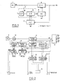
Ainsi qu'il apparaît sur la figure 1 précitée, le dispositif générateur comprend un oscillateur de référence, noté 1, permettant d'engendrer un signal de référence à fréquence arbitraire FHL. Un premier diviseur de fréquence, noté 2, à rapport de division N commandé reçoit le signal à fréquence arbitraire de référence FHL et délivre en fonctionne-ment un signal de sortie de fréquence instantanée FS. Le signal de sortie du premier diviseur 2 constitue le signal de sortie du disPositif générateur objet de l'invention. Une chaîne de commande du premier diviseur de fréquence 2 est alimentée par l'oscillateur de référence 1 et comporte, connectés en cascade, un deuxième diviseur de fréquence 3 à rapport de division commandé et un premier système intégrateur 4 programmable, dont la sortie délivre au premier diviseur de fréquence 2 la valeur du rapport de division instantané N.As shown in FIG. 1 above, the generator device comprises a reference oscillator, denoted 1, making it possible to generate a reference signal at arbitrary frequency FHL. A first frequency divider, denoted 2, with controlled division ratio N receives the signal of arbitrary frequency of reference FHL and delivers in operation a output signal of instantaneous frequency FS. The output signal of the
Une deuxième chaîne de commande du deuxième diviseur de fréquence 3 comporte un deuxième système intégrateur 5 recevant le signal de sortie de fréquence instantanée FS et délivre le rapport de division instantané au deuxième diviseur 3 à rapport de division commandé. Le premier 4 et deuxième 5 système intégrateur effectuent une intégration en grandeur et en signe opposé, le signe de l'intégration étant noté S avec S = ±1 , de leurs signaux d'entrée. Ainsi, le premier 4 et deuxième 5 système intégrateur présentent à chaque instant une fonction de transfert notée -S∫ et +S∫ ou réciproquement ainsi que noté en figure 1. Le premier 4 et le deuxième 5 système intégrateur sont susceptibles de permettre à l'origine du paramètre temps t une initialisation des rapports de division N et B des premier et deuxième diviseurs de fréquence 2, 3 aux valeurs No et Bo respectivement.A second control chain of the
Conformément à un mode de réalisation avantageux non limitatif du dispositif générateur, objet de l'invention, l'oscillateur de référence 1 peut être constitué par un générateur d'impulsions à fréquence de récurrence fixe piloté par quartz. Les premier 3 et deuxième 5 systèmes intégrateurs peuvent alors être constitués par des dispositifs compteurs-décompteurs d'impulsions.In accordance with an advantageous non-limiting embodiment of the generator device, object of the invention, the
De la même manière, les premier 2 et deuxième 3 diviseurs de fréquence à rapport de division commandé peuvent être constitués par des circuits à retard programmables et, avantageusement, par des circuits logiques binaires commandés assurant en fonction de leur rapport de division instantané respectif N, B, la division correspondante du nombre d'impulsions de leur signal d'entrée, ainsi qu'il sera explicité plus en détail ultérieurement dans la description.In the same way, the first 2 and second 3 frequency dividers with controlled division ratio can be constituted by programmable delay circuits and, advantageously, by controlled binary logic circuits ensuring as a function of their respective instantaneous division ratio N, B, the corresponding division of the number of pulses of their input signal, as will be explained in more detail later in the description.
Selon un mode de réalisation particulièrement avantageux non limitatif, représenté en figure 1, notamment, le deuxième diviseur 3 comporte, connectés en cascade, un premier diviseur de fréquence 30 de rapport de division A ajustable, indépendamment de la deuxième chaîne de commande et un deuxième diviseur de fréquence 31 à rapport de division commandé par la deuxième chaîne de la commande constituée par le deuxième système intégrateur.According to a particularly advantageous non-limiting embodiment, represented in FIG. 1, in particular, the
Le fonctionnement du dispositif générateur tel que représenté en figure 1 peut être décrit de la manière ci-après.The operation of the generator device as shown in FIG. 1 can be described as follows.
L'oscillateur 1 de référence engendre des impulsions à la fréquence de récurrence de référence FHL. Le premier diviseur de fréquence 2 délivre le signal de sortie de fréquence instantanée FS = FHL/N relation dans laquelle N est la valeur instantanée du rapport de division du premier diviseur 2. Le deuxième diviseur de fréquence 3, constitué par les deux diviseurs en cascade 30 et 31 délivre à sa sortie un signal de fréquence instantanée
relation dans laquelle B représente la valeur instantanée du rapport de division du diviseur 31. Le premier système intégrateur 4 permet en fonction de la valeur de S, S = ± 1 d'effectuer une intégration positive ou négative des impulsions à partir d'une valeur initiale No. Le premier système intégrateur 4 constitué par un compteur intégrateur ainsi que décrit précédemment permet d'effectuer un comptage ou un décomptage des impulsions reçues en fonction de la valeur du paramètre de signe S. Le premier système intégrateur 4 délivre la valeur instantanée du rapport de division N au premier diviseur 2.The
relation in which B represents the instantaneous value of the division ratio of the
Le deuxième système intégrateur 5 effectue également en fonction de la valeur du paramètre de signe S une intégration négative ou positive des impulsions à partir d'une valeur initiale Bo. Il effectue donc un décomptage ou un comptage des impulsions constituées par le signal de sortie de fréquence FS et délivre la valeur instantanée du rapport de division B au deuxième diviseur 3, plus particulièrement au diviseur programmable 31. Les différentes fonctions de transfert des éléments constitutifs du dispositif générateur objet de l'invention représenté en figure 1, s'écrivent :
B = S∫FSdt et le signal délivré par le deuxième diviseur 3 et plus particulièrement par le diviseur 31 s'écrit :
Le rapport de division N du premier diviseur 2 s'écrit :
et la fréquence FS du signal de sortie s'écrit
Pour une fréquence FS de la forme

B = S∫FSdt and the signal delivered by the
The division ratio N of the
and the frequency FS of the output signal is written
For a frequency FS of the form
La valeur du degré n du monome d'ordre n se détermine de façon que
et le degré n correspondant vérifie la relation :![]()
and the corresponding degree n checks the relation: ![]()
Pour A = 1, la fréquence FS du signal de sortie est FS = Ket, la valeur de K étant fixée par le passage de la courbe représentative de la loi de variation en un point qui peut être le premier point.For A = 1, the frequency FS of the output signal is FS = Ke t , the value of K being fixed by the passage of the curve representative of the law of variation at a point which may be the first point.
Ainsi, de par le principe de superposition des états d'équilibre physique, la fréquence FS du signal de sortie est bien une fréquence instantanée de la forme
en fonction de la valeur des paramètres A, Bo, No du dispositif générateur objet de l'invention.Thus, by the principle of superposition of the states of physical equilibrium, the frequency FS of the output signal is indeed an instantaneous frequency of the form
as a function of the value of the parameters A, Bo, No of the generator device which is the subject of the invention.
Le dispositif générateur tel que décrit en figure 1 et en figure 2 notamment, permet en fait d'obtenir une variation de la fréquence FS du signal de sortie selon des valeurs discrètes, la loi de variation étant matérialisée par une succession de points constitués en fait par les impulsions délivrées par le premier diviseur 2, la fréquence instantanée FS du signal de sortie étant définie comme l'inverse du temps qui sépare deux impulsions ou points consécutifs. En fait, le premier diviseur de fréquence 2 est un générateur programmé d'espace entre points : à chaque point ou impulsion délivrée par l'oscillateur de référence 1, il prend en compte la valeur N instantanée du rapport de division et attend N impulsions engendrées par l'oscillateur de référence 1 pour engendrer l'impulsion suivante constitutive du signal de sortie à fréquence FS.The generator device as described in FIG. 1 and in FIG. 2 in particular, makes it possible in fact to obtain a variation of the frequency FS of the output signal according to discrete values, the law of variation being materialized by a succession of points constituted in fact by the pulses delivered by the
Les points FSi de la courbe ou loi de variation de la fréquence de sortie FS sont définis de la manière ci-après, en fonction de chaque instant ti
où Ni représente la valeur du rapport de division N à l'instant i du premier diviseur 2, et la pente Pi de courbe ou loi de variation à l'instant ti s'écrit :
where Ni represents the value of the division ratio N at time i of the
A l'instant to de démarrage du dispositif générateur objet de l'invention, les premier et deuxième diviseurs sont initialisés aux valeurs No, A, Bo et la valeur de S est fixée. Une étude par itération pour S = 1 et Bo = 1 montre que la valeur du rapport de division Ni à l'instant ti du premier diviseur 2 s'écrit
L'expression δi représente l'atténuation en fréquence pour l'impulsion finale d'ordre i et
à l'instant ti + 1.The expression δi represents the frequency attenuation for the final pulse of order i and
at
De même, chaque instant d'ordre i + 1 vérifie la relation :
γi représentant l'image discrétisée de l'intégrale du temps.Similarly, each instant of order i + 1 checks the relation:
γi representing the discretized image of the time integral.
La valeur de K coefficient du monome de degré n peut alors être déterminée par
et le coefficient K précité vérifie la relation
and the aforementioned coefficient K verifies the relation
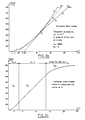
L'expression
tend vers une valeur constante α lorsque i tend vers l'infini pour une valeur donnée de A rapport de division du diviseur 30 et de n.The expression
tends to a constant value α when i tends to infinity for a given value of A division ratio of
Un exemple de valeurs correspondantes de A, n et α est donné dans le tableau ci-après.

La pente de la courbe ou loi de variation en un point Pi d'ordre i d'instant ti s'écrit
Dans le cas d'une loi de variation linéaire de la fréquence en fonction du temps, soit pour n = 1 et A = 2, la pente est égale à K.
L'expression
et l'expression
est un produit de Wallis tendant vers ![]()
La pente P s'écrit :
The expression
and the expression
is a product of Wallis tending towards ![]()
The slope P is written:
Conformément à une caractéristique avantageuse du dispositif générateur objet de l'invention, le premier diviseur de fréquence 30 peut être constitué par un diviseur de fréquence à rapport de division ajustable, la valeur du rapport de division A étant commandée à partir d'une commande extérieure. Il est ainsi possible de modifier la valeur du rapport de division A en cours de fonctionnement, ce qui a pour effet de modifier, au point considéré, le rayon de courbure de la loi de variation de fréquence selon une loi polynomiale du temps au point considéré.In accordance with an advantageous characteristic of the generator device which is the subject of the invention, the
La modification de la valeur du paramètre A par exemple en un point d'ordre i permet d'obtenir deux valeurs de pentes différentes soit par exemple:
Le rapport
est peu différent de ![]()
The report
is little different from ![]()
Conformément à une caractéristique avantageuse du dispositif générateur, objet de l'invention, le point anguleux peut être supprimé. Une première solution peut consister à conserver en chaque point d'ordre i - 1, i un produit A x δi sensiblement constant. La constance du produit A x δi peut être obtenue par modification temporaire locale de la valeur du rapport de division B du système intégrateur 5.In accordance with an advantageous characteristic of the generator device, object of the invention, the angular point can be eliminated. A first solution can consist in preserving at each point of order i - 1, i a product A x δi substantially constant. The constancy of the product A x δi can be obtained by temporary local modification of the value of the division ratio B of the integrating
Conformément à une variante de réalisation avantageuse du dispositif générateur objet de l'invention, la modification de pente en l'absence de point anguleux peut, de manière préférentielle, être obtenue au moyen d'une commande du rapport de division A par un circuit extérieur constitué par exemple par un circuit intégrateur. Sur la figure 2, le circuit intégrateur noté 6 est constitué par un compteur intégrateur.In accordance with an advantageous alternative embodiment of the generator device which is the subject of the invention, the change in slope in the absence of an angular point can preferably be obtained by means of a control of the division ratio A by an external circuit constituted for example by an integrating circuit. In FIG. 2, the integrator circuit noted 6 is constituted by an integrator counter.
En outre, lors de l'initialisation du dispositif générateur objet de l'invention, il est possible de fixer la valeur de Bo à une valeur supérieure à 1. Dans ce cas, tout se passe comme si la loi de variation de fréquence en fonction du temps était parcourue à partir d'un point translaté.In addition, during the initialization of the generator device which is the subject of the invention, it is possible to set the value of Bo to a value greater than 1. In this case, everything happens as if the law of frequency variation as a function time was traversed from a translated point.
Les différentes valeurs prises par N sont les suivantes :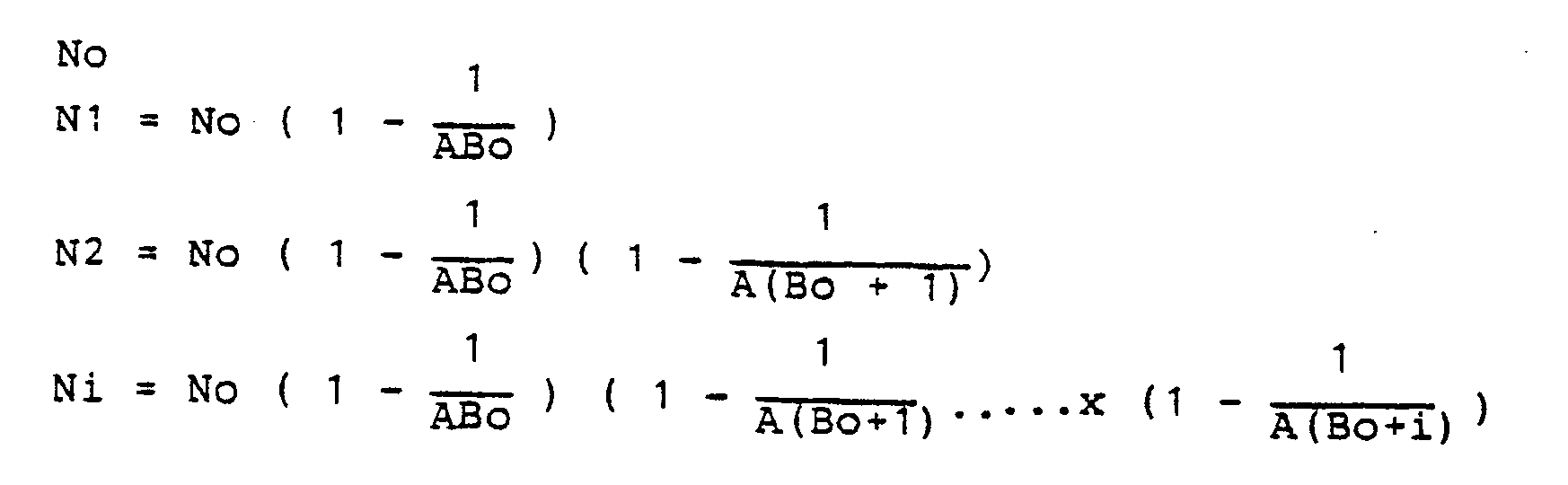
On peut aussi définir un point fictif Nʹo tel que
Dans ce cas, la valeur de K est :
et
le tableau donne la valeur du coefficient réducteur R :
We can also define a fictitious point Nʹo such that
In this case, the value of K is:
and
the table gives the value of the reducing coefficient R:
Ce coefficient réducteur est d'autant plus efficace que n est grand.This reducing coefficient is all the more effective when n is large.
A partir du premier point, la courbe décrite est telle que la valeur de la fréquence FS est donnée par
L'intérêt du coefficient réducteur est de pouvoir diminuer la valeur de K lorsqu'il n'est plus possible d'augmenter la valeur initiale No du fait de la capacité maximale des compteurs. Pour une valeur No donnée, on a un réseau de courbes qui passent par un point fixe de fréquence
Ceci a pour effet d'augmenter le temps de montée à une même fréquence.This has the effect of increasing the rise time at the same frequency.
Le sens de parcours de la courbe, c'est-à-dire la variation de la fréquence du signal de sortie FS, est déterminé par le signe de S. Le seul fait, à un instant déterminé, d'inverser le signe de S a pour effet d'inverser le sens de parcours et la variation de la fréquence FS du signal de sortie.The direction of travel of the curve, that is to say the variation of the frequency of the output signal FS, is determined by the sign of S. The only fact, at a determined instant, to reverse the sign of S has the effect of reversing the direction of travel and the variation of the frequency FS of the output signal.
Sur le schéma de la figure 2, on a représenté les différents constituants du dispositif objet de l'invention. L'oscillateur 1 peut de manière avantageuse, être constitué par un oscillateur générateur d'impulsions à 2 MHz de la série CEPE OM 16, le premier diviseur 2 par un diviseur 16 bits par exemple et le deuxième diviseur 3 peut être constitué par un premier diviseur ajustable de gain 2A,30,suivi d'un diviseur 16 bits. Le premier et le deuxième compteur intégrateur 4, 5, peuvent de même consister en un compteur 16 bits. Un compteur 4 bits 6 permet d'ajuster le diviseur ajustable 30. Un diviseur auxiliaire 12,diviseur par deux par exemple,permet en liaison avec le diviseur ajustable 30 d'obtenir un rapport des rapports de division correspondants en valeurs non entières.In the diagram of Figure 2, there is shown the various components of the device object of the invention. The
En outre, ainsi qu'il apparaît en figure 2, le dispositif objet de l'invention peut comprendre également, de manière avantageuse, une boucle de comparaison de la valeur de la fréquence instantanée FS du signal de sortie, comparateur numérique 7,à une valeur de seuil délivrée par un générateur de consigne programmable 8. De même, la valeur initiale No du premier intégrateur 4 est délivrée par un générateur de consigne numérique programmable 9. Les générateurs de consigne 8 et de valeur initiale 9 peuvent être programmés à partir de roues codeuses 10 ou à partir de tout autre moyen. En particulier, un microordinateur peut être utilisé. La boucle de comparaison permet, sur comparaison positive de la valeur de la fréquence instantanée FS, à la valeur de seuil ou consigne, une réinitialisation du système.In addition, as it appears in FIG. 2, the device which is the subject of the invention can also advantageously include a comparison loop of the value of the instantaneous frequency FS of the output signal,
En outre, et ainsi qu'il sera décrit ultérieurement dans la description de façon plus détaillée, la sortie à fréquence FS peut être reliée à un circuit générateur sinusoïdal 11, triphasé par exemple,en vue d'une utilisation pour la commande de moteurs synchrones.In addition, and as will be described later in the description in more detail, the frequency output FS can be connected to a
Sur la figure 3a, on a représenté un schéma d'un dispositif générateur conforme à l'objet de l'invention plus spécialement adapté en vue d'une utilisation pour la commande d'un moteur tel qu'un moteur synchrone.In Figure 3a, there is shown a diagram of a generator device in accordance with the object of the invention more specially adapted for use for controlling a motor such as a synchronous motor.
Ainsi qu'on pourra le remarquer, le dispositif générateur comporte dans ce cas, outre les éléments de la figure 2, une série de mémoires tampon 13, 14 interconnectées par une liaison de type BUS, bus de données, à un microordinateur par exemple. De même les générateurs de consigne 9, 8 et le compteur 4 bits 6 peuvent être remplacés par des mémoires tampons interconnectées au BUS de données.As will be noticed, the generator device comprises in this case, in addition to the elements of FIG. 2, a series of
Les diverses valeurs de consigne ou de commande sont alors mémorisées dans les mémoires tampon correspondantes.The various setpoint or control values are then stored in the corresponding buffer memories.
La mémoire 6 mémorise la valeur 2A qui permet de choisir la puissance de t ou degré du polynôme.The
Cette valeur peut être modifiée en cours de fonctionnement, par exemple pour démarrer avec une accélération croissant linéairement puis fonctionnement à accélération constante.This value can be modified during operation, for example to start with linearly increasing acceleration then operation at constant acceleration.
La mémoire 13 mémorise la valeur initiale Bo, la mémoire 9 la valeur No et la mémoire 8 la fréquence FS ou valeur de consigne à atteindre, laquelle s'analyse en la vitesse à atteindre par le moteur. Cette consigne peut être modifiée à tout instant.The
La mémoire 14 mémorise les ordres de commande par tout ou rien, tels que blocage du dispositif par valeur de la sortie D1, les premier 4 et deuxième 5 intégrateurs étant initialisés. Pour la valeur complémentée de D1,
Le circuit 15 permet l'adressage des diverses mémoires.
Sur la figure 3b on a représenté une loi de commande en vitesse d'un moteur synchrone. La courbe A est tracée avec α= 1 jusqu'à la fin du tracé, la courbe B est tracée avec α = 2 jusqu'au point M, elle est superposée à la courbe A. Au point M, on passe de α = 2 à α = 1 avec rupture de pente.In Figure 3b there is shown a speed control law of a synchronous motor. Curve A is plotted with α = 1 until the end of the plot, curve B is plotted with α = 2 up to point M, it is superimposed on curve A. At point M, we go from α = 2 at α = 1 with break in slope.
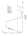
Sur la figure 3c, on a représenté une commande de moteur synchrone avec montée en vitesse selon une courbe en S. La partie de courbe notée γ1, pour α = 2, correspond à une accélération linéaire du type γ = γot. La partie de courbe notée γ2 correspond à une accélération constante γ2 = constante pour α= 1. La partie de courbe notée γ3 correspond pour α= 0,5, 04 ... à une décélération programmée.In FIG. 3c, a synchronous motor control is shown with speed increase according to an S curve. The part of the curve denoted γ1, for α = 2, corresponds to a linear acceleration of the type γ = γot. The part of the curve denoted γ2 corresponds to a constant acceleration γ2 = constant for α = 1. The part of the curve denoted γ3 corresponds for α = 0.5, 04 ... to a programmed deceleration.
Sur la figure 3d, on a enfin représenté la loi de variation de vitesse d'un moteur synchrone commandé en montée/descente selon une fonction du type n = ± Kt.In FIG. 3d, the law of speed variation of a synchronous motor controlled in ascent / descent according to a function of the type n = ± Kt is finally represented.
Sur les figures 3b, 3c, 3d, l'axe des abscisses est gradué en unité de temps,en secondes,et l'axe des ordonnées en nombre de tours par seconde.In FIGS. 3b, 3c, 3d, the abscissa axis is graduated in units of time, in seconds, and the ordinate axis in number of revolutions per second.
Une autre variante de réalisation du dispositif générateur, objet de l'invention, sera décrite en liaison avec la figure 4.Another alternative embodiment of the generator device, object of the invention, will be described in connection with FIG. 4.
Sur cette figure, on remarquera que la partie générateur du dispositif est identique au schéma de la figure 1. En outre, en vue d'engendrer une forme d'onde sinusoïdale à fréquence variable selon une loi de variation polynomiale du temps, le dispositif comprend en outre, connecté en sortie du premier diviseur de fréquence 2 à rapport de division commandé, un circuit de type bistable 40 permettant d'engendrer à partir du signal de sortie à fréquence FS un signal rectangulaire par exemple de même fréquence instantanée. En outre, un filtre de fréquence harmonique 41 est asservi à la fréquence fondamentale du signal rectangulaire et permet de délivrer un signal dont la fréquence correspond au premier harmonique du signal rectangulaire.In this figure, it will be noted that the generator part of the device is identical to the diagram in Figure 1. In addition, in order to generate a sinusoidal waveform with variable frequency according to a law of polynomial variation of time, the device comprises in addition, connected at the output of the
Dans l'utilisation précitée, le dispositif générateur, objet de l'invention, peut avantageusement trouver application aux circuits générateurs de fréquences pour radars à agilité de fréquence, aux systèmes d'émission à émission codée.In the aforementioned use, the generator device, object of the invention, can advantageously find application to frequency generator circuits for frequency-agile radars, to coded emission transmission systems.
Dans ce cas bien entendu, en fonction de la bande d'émission choisie, les circuits terminaux peuvent être réalisés en technologie TTLS ou ECL par exemple.In this case of course, depending on the transmission band chosen, the terminal circuits can be produced in TTLS or ECL technology for example.
Un autre mode de réalisation avantageux d'un dispositif générateur conforme à l'invention sera décrit en liaison avec les figures 5a et 5b dans le cas de la commande des moteurs pas à pas.Another advantageous embodiment of a generator device according to the invention will be described in connection with FIGS. 5a and 5b in the case of the control of stepping motors.
Dans cette utilisation, un gabarit de commande en vitesse est utilisé, gabarit tel que représenté en figure 5b par exemple.In this use, a speed control template is used, template as shown in Figure 5b for example.
Sur la figure 5a, le dispositif générateur conforme à la présente invention comporte sensiblement les mêmes éléments que le dispositif générateur représenté en figure 3a par exemple en ce qui concerne les éléments 13, 11, 9, 8, 14 et 15.In FIG. 5a, the generator device according to the present invention comprises substantially the same elements as the generator device shown in FIG. 3a, for example as
En outre, la consigne du nombre de pas est mémorisée dans la mémoire tampon 18 et un compteur de pas total 17 est initialisé au démarrage avec ce nombre de pas, comme la mémoire tampon 18. Le sens de rotation du moteur est commandé par une commande tout ou rien D3 délivrée par la mémoire 14, la commande agissant directement au niveau d'un circuit de commutation 50 délivrant un signal correspondant I⁺, I⁻. La sortie à fréquence FS est divisée par deux. Un compteur de pas à fréquence stable 16 est en outre prévu . Grâce aux deux compteurs 16 et 17 et au tampon 18 qui mémorise la consigne P, le gabarit est décrit correctement. A l'initialisation, les compteurs 16 et 17 sont chargés avec la valeur P. La variable discrète D1 mémorisée en 14 arme la bascule 19 qui débloque le système. La fréquence FS de sortie croît selon la pente programmée No, les compteurs 16, 17 décomptent de leur valeur initiale les impulsions vues en FS. Lorsque la vitesse maximale est atteinte, le comparateur 7 indique l'égalité et arme la bascule 20 qui bloque le compteur 16. Le compteur 17 continue à décompter les impulsions jusqu'à ce qu'il passe à zéro, ce point correspondant à un point de symétrie du gabarit. Le compteur 17 est alors rechargé avec la consigne P, la bascule 20 est désarmée, le compteur 16 est débloqué, son contenu représentant le nombre d'impulsions restant à fréquence constante. Lorsque le contenu du compteur 16 passe à zéro, le signe de S est inversé et la fréquence se met à décroître selon la pente programmée. Lorsque le compteur 17 passe de nouveau à zéro, la bascule 19 est désarmée et le système est bloqué jusqu'à une nouvelle commande. La variable discrète D2 permet de se placer en commande vitesse.In addition, the setpoint for the number of steps is stored in the
On a ainsi décrit un dispositif générateur de signaux à fréquence variable à haute performance dont la diversité d'applications montre tout l'intérêt. Le mode de réalisation décrit du dispositif selon l'invention en logique câblée n'est en aucun cas limitatif. Bien au contraire, le dispositif générateur peut de manière très avantageuse être réalisé sous forme de circuit intégré, tout au moins en ce qui concerne la partie générateur proprement dite.A high performance variable frequency signal generator device has thus been described, the variety of applications of which is of great interest. The described embodiment of the device according to the invention in wired logic is in no way limiting. On the contrary, the generator device can very advantageously be produced in the form of an integrated circuit, at least as regards the generator part proper.
Dans ce cas, le circuit intégré peut avantageusement être agencé de façon qu'il constitue un circuit périphérique de microprocesseur ou de l'unité centrale d'un microordinateur.In this case, the integrated circuit can advantageously be arranged so that it constitutes a peripheral circuit of microprocessor or of the central unit of a microcomputer.
Claims (14)
- A signal generator with variable frequency programmable according to a time-polynomial variation law, comprising:-
a reference oscillator (1) for generating a reference signal at an arbitrary frequency (FHL),
a first frequency divider (2) with a controlled division ratio (N), said first frequency divider (2) receiving said arbitrary frequency reference signal (FHL) and delivering in use an instantaneous frequency output signal (FS),
a control chain for said first frequency divider fed by said reference oscillator (1), characterized in that said control chain for said first frequency divider comprises, connected in cascade, a second frequency divider (3) with a controlled division ratio and a first programable integrator system (4) of which the output delivers to said first frequency divider (2) the value of said instantaneous division ratio (N),
a control chain for said second frequency divider (3) comprising a second integrator system (5) receiving said output signal (FS) and delivering said instantaneous division ratio to said second divider (3) with a controlled division ratio, said first (4) and second (5) integrator systems carrying out a magnitude integration at a sign (S) opposite to their input signals, said output signal (FS) having an instantaneous frequency of the polynomial form
- A device according to claim 1, wherein said reference oscillator controlled, fixed recurrence frequency.
- A device according to any one of claims 1 to 2, wherein said first and second integrator systems are constituted by up and down pulse counters.
- A device according to any one of claims 1 to 3, wherein said frequency dividers constituted by programmable delay circuits.
- A device according to any one of claims 1 to 3, wherein said frequency dividers (2),(3) with controlled division ratios are constituted by controlled binary logic circuits.
- A device according to any one of claims 2 or 3, wherein said second divider (3) comprises, connected in cascade, a first frequency divider (30) with a determined adjustable division ratio (A) and a second frequency divider (31) with a controlled division ratio (B).
- A device according to any one of claims 2 to 6, wherein said instantaneous frequency (FS) of said output signal is defined as the reciprocal of the time separating two pulses delivered by said first frequency divider (2).
- A device according to any one of claims 6 and 7, wherein said first frequency divider (30) with an adjustable division ratio (A) is a programmable divider controlled by an integrator circuit from a reference value, said control of the value of said division ratio A permitting continuous modification of the polynomial variation law for said frequency as a function of time.
- A device according to any one of claims 1 to 8, wherein said first (4) and second (5) integrator systems carry out magnitude integration at the sign (S) of their input signals permitting, as a function of the choice of said sign (S), a change of said polynomial variation law for said output frequency (FS) by values respectively increasing and decreasing said frequency as a function of time.
- A device according to any one of claims 1 to 9, further comprising a comparison loop for said value of said instantaneous frequency (FS) of said output signal with a programmable threshold value, said comparison loop permitting on positive comparison of said value of instantaneous frequency (FS) with said threshold value a resetting of said system.
- A device according to any one of claims 1 to 10, wherein in order to generate a sinusoidal wave form at variable frequency according to a time-polynomial variation law, said device further comprises, connected to an output of said first frequency divider (2) with a controlled division ratio, a bistable circuit permitting generation from said output signal at frequency (FS) a rectangular signal of the same instantaneous frequency, a harmonic frequency filter tuned to a fundamental frequency of said rectangular signal.
- A device according to any one of the claims mentioned above, wherein it is provided in the form of an integrated circuit.
- Use of a variable frequency signal generator according to any one of claims 1 to 12, for control of motors, wherein control parameters are memorised in auxiliary memories interconnected by a BUS type connection to either of a computer terminal or a micro-computer.
- Use according to claim 13, wherein in order to control a stepper motor, a speed control curve for the motor is used, said curve employing counting of the total number of steps made, counting of the maximum frequency of steps, control in rising and fall of speed of said motor being carried out by changing the sign of said integrator systems (4), (5).
Applications Claiming Priority (2)
| Application Number | Priority Date | Filing Date | Title |
|---|---|---|---|
| FR8609193A FR2600847B1 (en) | 1986-06-25 | 1986-06-25 | PROGRAMMABLE VARIABLE FREQUENCY SIGNAL GENERATING DEVICE |
| FR8609193 | 1986-06-25 |
Publications (2)
| Publication Number | Publication Date |
|---|---|
| EP0251908A1 EP0251908A1 (en) | 1988-01-07 |
| EP0251908B1 true EP0251908B1 (en) | 1991-10-30 |
Family
ID=9336695
Family Applications (1)
| Application Number | Title | Priority Date | Filing Date |
|---|---|---|---|
| EP87401473A Expired - Lifetime EP0251908B1 (en) | 1986-06-25 | 1987-06-25 | Programmable variable-frequency signal generator |
Country Status (4)
| Country | Link |
|---|---|
| US (1) | US4870366A (en) |
| EP (1) | EP0251908B1 (en) |
| DE (1) | DE3774193D1 (en) |
| FR (1) | FR2600847B1 (en) |
Families Citing this family (7)
| Publication number | Priority date | Publication date | Assignee | Title |
|---|---|---|---|---|
| DE3826006C1 (en) * | 1988-07-30 | 1989-10-12 | Wandel & Goltermann Gmbh & Co, 7412 Eningen, De | |
| US5095280A (en) * | 1990-11-26 | 1992-03-10 | Integrated Circuit Systems, Inc. | Dual dot clock signal generator |
| US5650738A (en) * | 1995-12-21 | 1997-07-22 | Hughes Aircraft Company | Precision digital phase shift element |
| US5703514A (en) * | 1995-12-21 | 1997-12-30 | Hughes Electronics | Digital frequency divider phase shifter |
| RU2168848C2 (en) * | 1999-08-27 | 2001-06-10 | Российский Федеральный Ядерный Центр - Всероссийский Научно-Исследовательский Институт Экспериментальной Физики | Fracture signal generator |
| US7304288B2 (en) * | 2005-07-06 | 2007-12-04 | The United States Of America As Represented By The Secretary Of The Navy | Laser pulse counter |
| TWI369879B (en) * | 2007-06-06 | 2012-08-01 | Qisda Corp | Method and apparatus for adjusting reference frequency |
Family Cites Families (8)
| Publication number | Priority date | Publication date | Assignee | Title |
|---|---|---|---|---|
| US3566096A (en) * | 1966-07-25 | 1971-02-23 | Pacific Ind Inc | Digital ratiometer |
| US3548320A (en) * | 1968-05-23 | 1970-12-15 | Us Navy | Digital fm sweep generator |
| SU596954A1 (en) * | 1975-05-26 | 1978-03-05 | Ордена Трудового Красного Знамени Институт Радиотехники И Электроники Ан Ссср | Arrangement for shaping signals with frequency varying by n-power polynom |
| US4103216A (en) * | 1976-05-28 | 1978-07-25 | Tally Corporation | Stepping motor closed loop constant velocity control system |
| JPS5485091A (en) * | 1977-12-20 | 1979-07-06 | Hitachi Ltd | Frequency sweeping circuit |
| FR2522826B1 (en) * | 1982-03-05 | 1986-01-31 | Thomson Csf | DEVICE FOR DIGITAL GENERATION OF A FREQUENCY MODULATED SIGNAL AND RADIO FREQUENCY DEVICE COMPRISING SUCH A DIGITAL DEVICE |
| US4450532A (en) * | 1982-04-19 | 1984-05-22 | General Electric Company | Voltage to frequency converter |
| FR2576470B1 (en) * | 1985-01-22 | 1989-05-26 | Veglia | VARIABLE OUTPUT FREQUENCY-FREQUENCY CONVERTER |
-
1986
- 1986-06-25 FR FR8609193A patent/FR2600847B1/en not_active Expired
-
1987
- 1987-06-23 US US07/065,560 patent/US4870366A/en not_active Expired - Fee Related
- 1987-06-25 EP EP87401473A patent/EP0251908B1/en not_active Expired - Lifetime
- 1987-06-25 DE DE8787401473T patent/DE3774193D1/en not_active Expired - Lifetime
Also Published As
| Publication number | Publication date |
|---|---|
| EP0251908A1 (en) | 1988-01-07 |
| FR2600847A1 (en) | 1987-12-31 |
| FR2600847B1 (en) | 1988-10-21 |
| US4870366A (en) | 1989-09-26 |
| DE3774193D1 (en) | 1991-12-05 |
Similar Documents
| Publication | Publication Date | Title |
|---|---|---|
| EP0251908B1 (en) | Programmable variable-frequency signal generator | |
| EP0142440A2 (en) | Generating device for a frequency being a fraction of a reference frequency | |
| EP0199613B1 (en) | Process and device to control the acceleration of an electric stepper motor | |
| FR2487142A1 (en) | CIRCUIT AND METHOD FOR A / D OR D / A CONVERSION OF BIPOLAR SIGNALS USING A SINGLE REFERENCE VOLTAGE | |
| EP0586696B1 (en) | Control device for maintaining an object in a given position | |
| FR2695211A1 (en) | Device and method for analyzing ILS signals. | |
| EP0207859B1 (en) | Discrete and shifting fourier transform calculating device, for using in a radar system | |
| EP0022695B1 (en) | Commutated filter unit | |
| EP0049652A1 (en) | Device for time compression and device for time decompression of data | |
| EP2978127A1 (en) | Method for digitally compensating variations, based on the temperature, of an electrical variable of an onboard spatial radio frequency telecommunications device | |
| EP0591813B1 (en) | Continuous phase modulator | |
| EP1887750A1 (en) | FSK modulator | |
| EP0075376B1 (en) | Method of management of the frequency control of a transmitter receiver and of the programmation of the programmable counter of his digital frequency synthesizer | |
| CH675937A5 (en) | ||
| EP1253512B1 (en) | Method and apparatus for generating a random signal with controlled histogram and spectrum | |
| CA1244920A (en) | Method and device for extending the frequency band of radar recurrences accepted by a digital image transformer | |
| EP3048730A1 (en) | Frequency synthesis device with feedback loop | |
| FR2624283A1 (en) | INTEGRATED DIGITAL CALCULATION CIRCUIT FOR SLIDE CALCULATIONS OF THE CONVOLUTION TYPE | |
| EP0621682B1 (en) | Frequency divider device | |
| FR2566132A1 (en) | Method and device for measuring the period of a quasi-sinusoidal signal and their applications | |
| EP0064902A1 (en) | Digital filters | |
| EP0585454B1 (en) | Incremental-decremental counter | |
| FR2755552A1 (en) | Clock signal duplication device for FIFO memory control | |
| EP0645892A1 (en) | Frequency-locked loop | |
| FR2576470A1 (en) | Frequency/frequency converter with variable output |
Legal Events
| Date | Code | Title | Description |
|---|---|---|---|
| PUAI | Public reference made under article 153(3) epc to a published international application that has entered the european phase |
Free format text: ORIGINAL CODE: 0009012 |
|
| AK | Designated contracting states |
Kind code of ref document: A1 Designated state(s): DE FR GB IT NL SE |
|
| 17P | Request for examination filed |
Effective date: 19880328 |
|
| 17Q | First examination report despatched |
Effective date: 19900713 |
|
| GRAA | (expected) grant |
Free format text: ORIGINAL CODE: 0009210 |
|
| AK | Designated contracting states |
Kind code of ref document: B1 Designated state(s): DE FR GB IT NL SE |
|
| GBT | Gb: translation of ep patent filed (gb section 77(6)(a)/1977) | ||
| REF | Corresponds to: |
Ref document number: 3774193 Country of ref document: DE Date of ref document: 19911205 |
|
| ITF | It: translation for a ep patent filed | ||
| PGFP | Annual fee paid to national office [announced via postgrant information from national office to epo] |
Ref country code: NL Payment date: 19920630 Year of fee payment: 6 |
|
| PLBE | No opposition filed within time limit |
Free format text: ORIGINAL CODE: 0009261 |
|
| STAA | Information on the status of an ep patent application or granted ep patent |
Free format text: STATUS: NO OPPOSITION FILED WITHIN TIME LIMIT |
|
| 26N | No opposition filed | ||
| PG25 | Lapsed in a contracting state [announced via postgrant information from national office to epo] |
Ref country code: NL Effective date: 19940101 |
|
| NLV4 | Nl: lapsed or anulled due to non-payment of the annual fee | ||
| EAL | Se: european patent in force in sweden |
Ref document number: 87401473.1 |
|
| PGFP | Annual fee paid to national office [announced via postgrant information from national office to epo] |
Ref country code: FR Payment date: 19980427 Year of fee payment: 12 |
|
| PGFP | Annual fee paid to national office [announced via postgrant information from national office to epo] |
Ref country code: SE Payment date: 19980617 Year of fee payment: 12 Ref country code: DE Payment date: 19980617 Year of fee payment: 12 |
|
| PGFP | Annual fee paid to national office [announced via postgrant information from national office to epo] |
Ref country code: GB Payment date: 19980619 Year of fee payment: 12 |
|
| PG25 | Lapsed in a contracting state [announced via postgrant information from national office to epo] |
Ref country code: GB Free format text: LAPSE BECAUSE OF NON-PAYMENT OF DUE FEES Effective date: 19990625 |
|
| PG25 | Lapsed in a contracting state [announced via postgrant information from national office to epo] |
Ref country code: SE Free format text: THE PATENT HAS BEEN ANNULLED BY A DECISION OF A NATIONAL AUTHORITY Effective date: 19990629 |
|
| PG25 | Lapsed in a contracting state [announced via postgrant information from national office to epo] |
Ref country code: FR Free format text: THE PATENT HAS BEEN ANNULLED BY A DECISION OF A NATIONAL AUTHORITY Effective date: 19990630 |
|
| GBPC | Gb: european patent ceased through non-payment of renewal fee |
Effective date: 19990625 |
|
| EUG | Se: european patent has lapsed |
Ref document number: 87401473.1 |
|
| PG25 | Lapsed in a contracting state [announced via postgrant information from national office to epo] |
Ref country code: DE Free format text: LAPSE BECAUSE OF NON-PAYMENT OF DUE FEES Effective date: 20000503 |
|
| REG | Reference to a national code |
Ref country code: FR Ref legal event code: ST |
|
| PG25 | Lapsed in a contracting state [announced via postgrant information from national office to epo] |
Ref country code: IT Free format text: LAPSE BECAUSE OF NON-PAYMENT OF DUE FEES;WARNING: LAPSES OF ITALIAN PATENTS WITH EFFECTIVE DATE BEFORE 2007 MAY HAVE OCCURRED AT ANY TIME BEFORE 2007. THE CORRECT EFFECTIVE DATE MAY BE DIFFERENT FROM THE ONE RECORDED. Effective date: 20050625 |