EP0250675B1 - Supraleitender Magnet - Google Patents
Supraleitender Magnet Download PDFInfo
- Publication number
- EP0250675B1 EP0250675B1 EP86306089A EP86306089A EP0250675B1 EP 0250675 B1 EP0250675 B1 EP 0250675B1 EP 86306089 A EP86306089 A EP 86306089A EP 86306089 A EP86306089 A EP 86306089A EP 0250675 B1 EP0250675 B1 EP 0250675B1
- Authority
- EP
- European Patent Office
- Prior art keywords
- coil
- superconducting
- heat insulation
- superconducting magnet
- vacuum heat
- Prior art date
- Legal status (The legal status is an assumption and is not a legal conclusion. Google has not performed a legal analysis and makes no representation as to the accuracy of the status listed.)
- Expired - Lifetime
Links
Images

Classifications
-
- G—PHYSICS
- G01—MEASURING; TESTING
- G01R—MEASURING ELECTRIC VARIABLES; MEASURING MAGNETIC VARIABLES
- G01R33/00—Arrangements or instruments for measuring magnetic variables
- G01R33/20—Arrangements or instruments for measuring magnetic variables involving magnetic resonance
- G01R33/28—Details of apparatus provided for in groups G01R33/44 - G01R33/64
- G01R33/42—Screening
- G01R33/421—Screening of main or gradient magnetic field
-
- G—PHYSICS
- G01—MEASURING; TESTING
- G01R—MEASURING ELECTRIC VARIABLES; MEASURING MAGNETIC VARIABLES
- G01R33/00—Arrangements or instruments for measuring magnetic variables
- G01R33/20—Arrangements or instruments for measuring magnetic variables involving magnetic resonance
- G01R33/28—Details of apparatus provided for in groups G01R33/44 - G01R33/64
- G01R33/38—Systems for generation, homogenisation or stabilisation of the main or gradient magnetic field
- G01R33/381—Systems for generation, homogenisation or stabilisation of the main or gradient magnetic field using electromagnets
- G01R33/3815—Systems for generation, homogenisation or stabilisation of the main or gradient magnetic field using electromagnets with superconducting coils, e.g. power supply therefor
-
- H—ELECTRICITY
- H01—ELECTRIC ELEMENTS
- H01F—MAGNETS; INDUCTANCES; TRANSFORMERS; SELECTION OF MATERIALS FOR THEIR MAGNETIC PROPERTIES
- H01F6/00—Superconducting magnets; Superconducting coils
Definitions
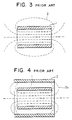
- Fig. 3 shows a sectional view of a prior-art magnet.
- numeral 1 designates a coil which generates a magnetic field 2 when a current flows through the winding thereof.
- a magnet whose coil is small generates a weak magnetic field and is often used without providing a magnetic shield as shown in Fig. 3, since the magnetic field exerts little influence on the surroundings.
- Fig. 4 shows a sectional view of another example.
- numeral 1 designates a coil by which magnetic fluxes 2a are generated.
- Numeral 3 designates a magnetic shield which is made of a ferromagnetic substance.
- the prior-art magnets are constructed as shown in Figs. 3 and 4.
- the magnetic fluxes 2 interlinking with the coil 1 are generated by energizing the coil.
- Most of the magnetix fluxes 2 extend along the inner periphery of the coil 1, and some of them traverse the coil 1, to pass through the interior of the coil 1, whereupon the magnetic fluxes 2 extend outside the outer periphery of the coil 1 and enter the interior of the coil 1.
- the magnetic fluxes depict loops.
- the magnetic fluxes extending outside the outer periphery of the coil 1 spread spaciously, and a region which has an intense magnetic field becomes large. Accordingly, when the magnetic disk device or the like of a computer or the like, which is susceptible to a magnetic field, is located in the vicinity of this intense magnetic field, it malfunction may arise.
- the magnetic fluxes 2a interlinking with the coil are generated by energizing the coil 1 as in the case of Fig. 3.
- the magnetic shield 3 made of the ferromagnetic substance of high permeability is disposed outside the outer periphery of the coil 1 as shown in Fig. 4, most of the magnetic fluxes 2a generated by the coil 1 are contained inside the magnetic shield 3, and the magnetic fluxes which pass outside the magnetic shield 3 lessen to narrow the region having an intense magnetic field. Accordingly, even when equipment liable to be influenced by a magnetic field is installed near the magnet, it is not influenced thereby.
- a superconducting magnet is received in a vacuum heat insulation vessel. Therefore, when the magnetic shield of the type described above is applied to the superconducting magnet, it needs to be disposed around the outer periphery of the vacuum heat insulation vessel, resulting in the problem that the geometry of the superconducting magnet enlarges. Another problem is that the double vessel structure consisting of the magnetic shield and the vacuum heat insulation vessel is uneconomical.
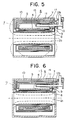
- numeral 4 designates a superconducting coil which is constructed by winding a superconducting wire.
- a liquid helium tank 5 receives the superconducting coil 4, and contains a cryogen such as liquid helium for cooling the superconducting coil 4.
- Numeral 6 generally designates a vacuum heat insulation vessel which receives the liquid helium tank 5, and has its interior evacuated for heat insulation.
- An outer cylinder 7 lies at the outer peripheral part of the vacuum heat insulation vessel 6 and is made of a ferromagnetic material of high permeability having a thickness sufficient to exhibit a magnetic shield effect.
- An inner cylinder 8 forms the inner periphery of the vacuum heat insulation vessel 6.
- Flanges 9 correspond to the end parts of the vacuum heat insulation vessel 6.
- Shown at numeral 10 is a thermal shield which lies between the liquid helium tank 5 and the vacuum heat insulation vessel 6, and which surrounds the liquid helium tank 5.
- This thermal shield 10 is mounted for the purpose of reducing the quantity of heat to enter the liquid helium tank 5, and it is cooled by liquid nitrogen.
- a communication pipe 11 holds the liquid helium tank 5 and the exterior of the vessel 6 in communication, while a communication pipe 12 holds the thermal shield 10 and the exterior of the vessel 6 in communication.
- a projection 13 is provided in order to lengthen the communication pipes and to set sufficient heat insulation distances. Magnetic fluxes 2b are generated by the superconducting coil 4.
- the magnetic fluxes 2b are generated so as to interlink with the superconducting coil 4 when conducting current through this coil.
- Most of the magnetic fluxes 2b extend along the inner periphery of the superconducting coil 4, and some of them traverse the superconducting coil 4, whereupon they extend along the outer periphery of the superconducting coil 4.
- Outside the outer periphery of the superconducting coil 4 most of the magnetic fluxes pass through the outer cylinder 7 of the vacuum heat insulation vessel 6 having the function of the magnetic shield, and they return inside the superconducting coil 4.
- the magnetic fluxes 2b form loops.
- An aim of the present invention is not only to provide a more economical and smaller superconducting magnet than previously known but also one which provides a uniform magnetic field.
- a superconducting magnet which comprises: a superconducting coil which generates a magnetic field when current is caused to flow therethrough; and a vacuum heat insulation vessel which serves to receive the coil and to hold it at a cryogenic temperature, wherein the vacuum heat insulation vessel has an outer cylindrical wall made of a ferromagnetic material which exhibits a magnetic shield effect; characterised in that a communication pipe passes through an end portion of vacuum heat insulation vessel, thereby enabling said outer cylindrical wall to be substantially symmetrically disposed with respect to the superconducting coil.
- Fig. 5 shows a superconducting magnet embodying the present invention.
- a communication pipe 11 passes through the flange 9 instead of through the outer cylinder 7 and is disposed with its longitudinal axis lying substantially horizontally with respect to the axis of the superconducting coil 4.
- the end 15 of the communication pipe 11 is located mid-way along the length of the superconducting coil 4 between the flanges 9.
- the positioning of the communication pipe 11 as illustrated in Fig. 5 is such as to enable the outer cylinder 7 to be completely symmetrical with respect to the superconducting coil 4. This results in an improvement in the uniformity of the magnetic field around the superconducting magnet.
- the embodiment described above is particularly advantageous for a superconducting magnet for a MRI (magnetic resonance imaging system) which needs a uniform magnetic field.
- Fig. 6 shows another embodiment of a superconducting magnet in which a communication pipe 11 is disposed substantially horizontally in the same manner as in Fig. 5.
- the flanges 9 are formed of ferromagnetic material having sufficient thickness to provide a magnetic shielding effect.
- the communication pipe 11 passes through a hole in the flange 9.
- This embodiment has the advantages of the symmetrical outer cylinder 7 described with reference to Fig. 5, but the magnetic shielding performance is further improved due to the presence of the flanges 9.
- a communication pipe 12b passes from the thermal shield 10 to the exterior of the vessel 6 via the flange 9. Passing the pipe 12b through the flange 9 also enables the outer cylinder 7 to be completely symmetrical.
- the communication pipe 11 is passed through an end wall of the liquid helium tank 5 and a seal is provided between the pipe and the end wall by way of a bellows joint 16.
- the bellows joint 16 enables the effects of expansion between the pipe and the liquid helium tank 5 to be compensated for in addition to providing the seal.
- the communication pipe 11 provides a means whereby gas may be discharged into the atmosphere from the liquid helium tank 5.
- the communication pipe 11 may also serve to carry and support power leads (not shown) for the superconducting coil 4.
Landscapes
- Physics & Mathematics (AREA)
- Condensed Matter Physics & Semiconductors (AREA)
- General Physics & Mathematics (AREA)
- Electromagnetism (AREA)
- Engineering & Computer Science (AREA)
- Power Engineering (AREA)
- Health & Medical Sciences (AREA)
- Epidemiology (AREA)
- Magnetic Resonance Imaging Apparatus (AREA)
- Containers, Films, And Cooling For Superconductive Devices (AREA)
Claims (5)
- Supraleitender Magnet, der folgendes aufweist:- eine supraleitende Spule (4), die ein Magnetfeld erzeugt, wenn man einen Strom durch sie hindurchfließen läßt; und- einen Vakuum-Wärmeisolierbehälter (6), der dazu dient, die Spule aufzunehmen und sie auf einer kryogenen Temperatur zu halten, wobei der Vakuum-Wärmeisolierbehälter (6) eine zylindrische Außenwand (7) hat, die aus einem ferromagnetischen Material besteht, das einen magnetischen Abschirmeffekt zeigt;dadurch gekennzeichnet,
daß ein Verbindungsrohr (11) durch einen Endabschnitt (9) des Vakuum-Wärmeisolierbehälters (6) verläuft, so daß eine im wesentlichen symmetrische Anordnung der zylindrischen Außenwand (7) in bezug auf die supraleitende Spule (4) möglich ist. - Supraleitender Magnet nach Anspruch 1,
bei dem beide Endabschnitte (9) des Vakuum-Wärmeisolierbehälters (6) durchgehend mit dem äußeren Zylinderbereich ausgebildet sind und aus dem ferromagnetischen Material bestehen, um den magnetischen Abschirmeffekt zu bewirken. - Supraleitender Magnet nach Anspruch 1 oder 2,
bei dem ein Ende (15) des Verbindungsrohrs (11) in der Mitte entlang der Länge der supraleitenden Spule zwischen den Endabschnitten angeordnet ist. - Supraleitender Magnet nach einem der Ansprüche 1 bis 3,
der ferner eine Balgenverbindung (16) aufweist, um eine Abdichtung zwischen dem Verbindungsrohr (11) und dem Endabschnitt (9) zu bilden. - Supraleitender Magnet nach Anspruch 4, wenn dieser auf Anspruch 3 rückbezogen ist,
wobei der Magnet einen Behälter (5) aufweist, um ein Kältemittel zum Kühlen der supraleitenden Spule (4) aufzunehmen, wobei die Balgenverbindung innerhalb des Behälters (5) und außerhalb der supraleitenden Spule (4) angeordnet ist.
Applications Claiming Priority (2)
| Application Number | Priority Date | Filing Date | Title |
|---|---|---|---|
| US06/870,376 US4707676A (en) | 1985-01-01 | 1986-06-04 | Superconducting magnet |
| US870376 | 1986-06-04 |
Publications (2)
| Publication Number | Publication Date |
|---|---|
| EP0250675A1 EP0250675A1 (de) | 1988-01-07 |
| EP0250675B1 true EP0250675B1 (de) | 1992-10-21 |
Family
ID=25355250
Family Applications (1)
| Application Number | Title | Priority Date | Filing Date |
|---|---|---|---|
| EP86306089A Expired - Lifetime EP0250675B1 (de) | 1986-06-04 | 1986-08-06 | Supraleitender Magnet |
Country Status (2)
| Country | Link |
|---|---|
| EP (1) | EP0250675B1 (de) |
| DE (1) | DE3686999T2 (de) |
Cited By (1)
| Publication number | Priority date | Publication date | Assignee | Title |
|---|---|---|---|---|
| US7040099B2 (en) | 2001-11-21 | 2006-05-09 | Siemens Aktiengesellschaft | Cryostat |
Families Citing this family (4)
| Publication number | Priority date | Publication date | Assignee | Title |
|---|---|---|---|---|
| IL90050A (en) * | 1989-04-23 | 1992-07-15 | Elscint Ltd | Integrated active shielded magnet system |
| JP3102492B2 (ja) * | 1990-07-20 | 2000-10-23 | 株式会社日立製作所 | 防振型クライオスタツト |
| DE10251449B4 (de) | 2001-11-21 | 2004-12-30 | Siemens Ag | Kryostat |
| CN101877268A (zh) * | 2010-06-13 | 2010-11-03 | 江苏旌凯中科超导高技术有限公司 | 通用型超导磁体系统 |
Citations (2)
| Publication number | Priority date | Publication date | Assignee | Title |
|---|---|---|---|---|
| EP0111218A2 (de) * | 1982-12-11 | 1984-06-20 | Bruker Analytische Messtechnik GmbH | Elektromagnet für die NMR-Tomographie |
| US4484814A (en) * | 1982-05-28 | 1984-11-27 | Mitsubishi Denki Kabushiki Kaisha | Superconductive magnet |
Family Cites Families (2)
| Publication number | Priority date | Publication date | Assignee | Title |
|---|---|---|---|---|
| DE1514708A1 (de) * | 1966-03-17 | 1969-06-19 | Siemens Ag | Fluessigkeitsgekuehlte Magnetspule |
| GB1324402A (en) * | 1971-04-19 | 1973-07-25 | Int Research & Dev Co Ltd | Superconducting coils |
-
1986
- 1986-08-06 EP EP86306089A patent/EP0250675B1/de not_active Expired - Lifetime
- 1986-08-06 DE DE19863686999 patent/DE3686999T2/de not_active Expired - Fee Related
Patent Citations (2)
| Publication number | Priority date | Publication date | Assignee | Title |
|---|---|---|---|---|
| US4484814A (en) * | 1982-05-28 | 1984-11-27 | Mitsubishi Denki Kabushiki Kaisha | Superconductive magnet |
| EP0111218A2 (de) * | 1982-12-11 | 1984-06-20 | Bruker Analytische Messtechnik GmbH | Elektromagnet für die NMR-Tomographie |
Non-Patent Citations (1)
| Title |
|---|
| Clarendon Press Oxford, 1983 M.N. Wilson "Superconducting magnets", pages 7, 251-253 * |
Cited By (1)
| Publication number | Priority date | Publication date | Assignee | Title |
|---|---|---|---|---|
| US7040099B2 (en) | 2001-11-21 | 2006-05-09 | Siemens Aktiengesellschaft | Cryostat |
Also Published As
| Publication number | Publication date |
|---|---|
| DE3686999T2 (de) | 1993-06-03 |
| EP0250675A1 (de) | 1988-01-07 |
| DE3686999D1 (de) | 1992-11-26 |
Similar Documents
| Publication | Publication Date | Title |
|---|---|---|
| US4590428A (en) | Electromagnet for NMR tomography | |
| US4707676A (en) | Superconducting magnet | |
| US5018359A (en) | Cryogenic refrigeration apparatus | |
| EP0773565B1 (de) | Offener kryogengekühlter supraleitender Magnet für die Bilderzeugung durch magnetische Resonanz | |
| JPH0418189B2 (de) | ||
| JP2000294399A (ja) | 超電導高周波加速空胴及び粒子加速器 | |
| US6501275B1 (en) | Gradient coil arrangement comprising dampening of inner mechanical vibrations | |
| US20050202976A1 (en) | Apparatus for use in nmr system | |
| JP2007027715A (ja) | 超伝導マグネット向けの低磁場損失コールドマス構造体 | |
| CN101226809A (zh) | 超导磁铁装置及磁共振摄像装置 | |
| EP0250675B1 (de) | Supraleitender Magnet | |
| JPH09120912A (ja) | 開構造伝導冷却型磁気共鳴作像マグネット | |
| US5225782A (en) | Eddy current free MRI magnet with integrated gradient coils | |
| EP0936290B1 (de) | Supraleitende Magnetvorrichtung für eine Kristallziehungsvorrichtung | |
| US8171741B2 (en) | Electrically conductive shield for refrigerator | |
| US7005953B2 (en) | Magnet system with shielded regenerator material | |
| US20080271467A1 (en) | Refrigerator Interface for Cryostat | |
| WO2005116516A1 (en) | Refrigerator interface for cryostat | |
| JPS63292608A (ja) | 電磁石装置 | |
| JP2002359111A (ja) | 水平方向磁場発生用超電導マグネット | |
| JP2001044020A (ja) | 伝導冷却型超電導マグネット装置およびその組立て方法 | |
| JPS62169311A (ja) | Nmrイメ−ジング用超伝導磁石装置 | |
| JPH0729724A (ja) | 超電導電磁石 | |
| JPH047807A (ja) | 超電導マグネット用低温容器 | |
| JP2931168B2 (ja) | 超電導磁石装置 |
Legal Events
| Date | Code | Title | Description |
|---|---|---|---|
| PUAI | Public reference made under article 153(3) epc to a published international application that has entered the european phase |
Free format text: ORIGINAL CODE: 0009012 |
|
| AK | Designated contracting states |
Kind code of ref document: A1 Designated state(s): DE GB NL |
|
| 17P | Request for examination filed |
Effective date: 19880203 |
|
| 17Q | First examination report despatched |
Effective date: 19900810 |
|
| GRAA | (expected) grant |
Free format text: ORIGINAL CODE: 0009210 |
|
| AK | Designated contracting states |
Kind code of ref document: B1 Designated state(s): DE GB NL |
|
| REF | Corresponds to: |
Ref document number: 3686999 Country of ref document: DE Date of ref document: 19921126 |
|
| REG | Reference to a national code |
Ref country code: GB Ref legal event code: 727 |
|
| REG | Reference to a national code |
Ref country code: GB Ref legal event code: 727A |
|
| REG | Reference to a national code |
Ref country code: GB Ref legal event code: 727B |
|
| REG | Reference to a national code |
Ref country code: GB Ref legal event code: 727B |
|
| REG | Reference to a national code |
Ref country code: GB Ref legal event code: SP |
|
| PLBE | No opposition filed within time limit |
Free format text: ORIGINAL CODE: 0009261 |
|
| STAA | Information on the status of an ep patent application or granted ep patent |
Free format text: STATUS: NO OPPOSITION FILED WITHIN TIME LIMIT |
|
| 26N | No opposition filed | ||
| REG | Reference to a national code |
Ref country code: GB Ref legal event code: 746 Effective date: 19960611 |
|
| PGFP | Annual fee paid to national office [announced via postgrant information from national office to epo] |
Ref country code: GB Payment date: 19960729 Year of fee payment: 11 |
|
| PGFP | Annual fee paid to national office [announced via postgrant information from national office to epo] |
Ref country code: DE Payment date: 19960812 Year of fee payment: 11 |
|
| PG25 | Lapsed in a contracting state [announced via postgrant information from national office to epo] |
Ref country code: GB Free format text: LAPSE BECAUSE OF NON-PAYMENT OF DUE FEES Effective date: 19970806 |
|
| PGFP | Annual fee paid to national office [announced via postgrant information from national office to epo] |
Ref country code: NL Payment date: 19970826 Year of fee payment: 12 |
|
| GBPC | Gb: european patent ceased through non-payment of renewal fee |
Effective date: 19970806 |
|
| PG25 | Lapsed in a contracting state [announced via postgrant information from national office to epo] |
Ref country code: DE Free format text: LAPSE BECAUSE OF NON-PAYMENT OF DUE FEES Effective date: 19980501 |
|
| PG25 | Lapsed in a contracting state [announced via postgrant information from national office to epo] |
Ref country code: NL Free format text: LAPSE BECAUSE OF NON-PAYMENT OF DUE FEES Effective date: 19990301 |
|
| NLV4 | Nl: lapsed or anulled due to non-payment of the annual fee |
Effective date: 19990301 |