EP0250387B1 - Dispositif de commande d'un tube de poche de coulée - Google Patents
Dispositif de commande d'un tube de poche de coulée Download PDFInfo
- Publication number
- EP0250387B1 EP0250387B1 EP87870073A EP87870073A EP0250387B1 EP 0250387 B1 EP0250387 B1 EP 0250387B1 EP 87870073 A EP87870073 A EP 87870073A EP 87870073 A EP87870073 A EP 87870073A EP 0250387 B1 EP0250387 B1 EP 0250387B1
- Authority
- EP
- European Patent Office
- Prior art keywords
- ladle
- casting
- arm
- supporting collar
- pivot
- Prior art date
- Legal status (The legal status is an assumption and is not a legal conclusion. Google has not performed a legal analysis and makes no representation as to the accuracy of the status listed.)
- Expired - Lifetime
Links
- 238000009434 installation Methods 0.000 title 1
- 239000000725 suspension Substances 0.000 claims description 10
- 230000001681 protective effect Effects 0.000 claims 1
- 229910000831 Steel Inorganic materials 0.000 description 4
- 238000005266 casting Methods 0.000 description 4
- 239000010959 steel Substances 0.000 description 4
- 229910001338 liquidmetal Inorganic materials 0.000 description 3
- 229910045601 alloy Inorganic materials 0.000 description 2
- 239000000956 alloy Substances 0.000 description 2
- 238000011109 contamination Methods 0.000 description 2
- 230000006978 adaptation Effects 0.000 description 1
- 230000000694 effects Effects 0.000 description 1
- 239000007788 liquid Substances 0.000 description 1
- 238000000034 method Methods 0.000 description 1
- 230000003647 oxidation Effects 0.000 description 1
- 238000007254 oxidation reaction Methods 0.000 description 1
- 230000035515 penetration Effects 0.000 description 1
- 239000011819 refractory material Substances 0.000 description 1
- 239000002893 slag Substances 0.000 description 1
Images

Classifications
-
- B—PERFORMING OPERATIONS; TRANSPORTING
- B22—CASTING; POWDER METALLURGY
- B22D—CASTING OF METALS; CASTING OF OTHER SUBSTANCES BY THE SAME PROCESSES OR DEVICES
- B22D41/00—Casting melt-holding vessels, e.g. ladles, tundishes, cups or the like
- B22D41/50—Pouring-nozzles
- B22D41/56—Means for supporting, manipulating or changing a pouring-nozzle
Definitions
- the present invention relates to a device for controlling a ladle, which is made of a particular refractory material and which is applied under the casting drawer in order to protect the jet of liquid metal leaving the ladle. pouring, so as to avoid contamination by air.
- a device for controlling a ladle ladle comprising an arm mounted on a tilting point which is provided, on the one hand, with a control handle and , on the other hand, a bracket whose end of each branch has a housing for a pivot integral with a support ring for the ladle known in itself.
- the aim of the present invention is to provide a device for controlling such a ladle ladle tube which allows said tube to be easily applied in a sealed manner against the nozzle of the drawer, whether it is a linear drawer or of a rotary drawer, and which adapts to the pockets mounted on a lifting turnstile as well as to the pockets mounted on a simple turnstile.
- the device for controlling a ladle with a ladle comprising an arm mounted on a tipping point, which is provided, on the one hand, with a control handle and, on the other hand, 'A stirrup whose end of each branch has a housing for a pivot secured to a ring for supporting the ladle known in the art, has on the side of the control handle, an adjustable weight.
- the adjustable counterweight is mounted so as to be able to move along the arm, on one side of the tipping point, by means of an electric or pneumatic drive motor controlled by an operator using mounted switches. , for example, on the handle.
- the tiltable arm can also rotate around its longitudinal axis. In this way, it is possible to position the pouring ladle tube at the desired inclination to guarantee the desired tightness at the pouring drawer and also to facilitate the positioning of the ladle tube in the distributor.
- the tiltable arm is mounted on a pivot which is itself secured to a bracket which is again mounted on a pivot. It is easy to understand that in this way the arm can carry out a series of movements which makes it possible to move it aside or to approach it from a ladle which is either mounted on a lifting turnstile or on a simple turntable.
- the tube rests by means of a flange on a ring which is housed by means of two pivots in the branches of a mounted stirrup at the opposite end of said arm.
- said tube rests on the small ring by means of a movable ring mounted on said ring by means of balls. In this way, the tube can perform a tilting movement and a rotational movement along its own longitudinal axis.
- the device for controlling a ladle ladle consists of an arm 1 supported, in its middle by a universal toggle 3 allowing rotation along a vertical axis 5, a horizontal axis 7 and following the very axis of said arm, thus allowing the lateral inclination of the ladle located at the end of said arm.
- the toggle 3 supporting said arm is itself supported by a bracket 9 fixed to the casting floor by means of a pivot 11. A multitude of movements is thus obtained which make it possible to scan a larger area with the ladle.
- One end of the arm is provided with a. counterweight 13 which makes it possible to obtain, in addition to the balance of the tube, a vertical upward force applying the pocket tube to the nozzle of the drawer with sufficient force to ensure the tightness of the fitting between the neck of the tube known per se and the nose of the nozzle of the tundish.
- the counterweight is made movable along the shaft using a screw driven by a geared motor 15. The use of a counterweight also makes it possible to fill a constant application effect, after adjustment, whatever the height of the pocket in the case where the pocket is placed on a turnstile of the lifting type for example.
- the counterweight In the absence of electrical or pneumatic energy, the counterweight also makes it possible to maintain an intact force for applying the ladle to the pouring spout, which constitutes essential safety in the presence of liquid steel during casting. .
- the various combinations of movements described above allow the loading of the ladle tube onto its suspension device, to handle it from the floor to the ladle whose position XY can be variable as well as its trim and its altitude.
- the control according to the present invention allows the pouring ladle tube to follow the drawer in all its excursions, while keeping the connection and tightness permanent.
- the various movements of the device according to the present invention are obtained by push buttons 17 and 18 installed on the control handle at the end of the arm.
- the opposite end of the arm comprises a stirrup 19, each branch of which is provided with a housing 21 for a pivot 23 secured to a ring 25.
- Said ring 25 supports, by means of balls 27, a movable ring 29 on which is supported by the ladle ladle 31 known per se.
- the arrangement according to the present invention allows the ladle to remain constantly aligned with the nozzle of the drawer and allows its relative rotation relative to the stirrup during all the movements of the drawer in operation.
- suspension device according to the present invention lies in the reduction of the friction between the stirrup and the tube, during the operation of the drawer, even in the presence of very high temperatures to which the suspension device described is subjected, while maintaining good operating stability and an acceptable service life.
- it is advantageously cooled, by natural convection or by a jet of compressed air.
- the suspension device is protected by a screen 33 which prevents the penetration of projections and droplets of steel, slag or other liquid metal from entering the suspension device.
Landscapes
- Engineering & Computer Science (AREA)
- Mechanical Engineering (AREA)
- Continuous Casting (AREA)
- Casting Support Devices, Ladles, And Melt Control Thereby (AREA)
- Furnace Charging Or Discharging (AREA)
Description
- La présente invention est relative à un dispositif de commande d'un tube de poche de coulée, qui est constitué par un matériau réfractaire particulier et qui est appliqué sous le tiroir de coulée en vue de protéger le jet de métal liquide sortant de la poche de coulée, de manière à éviter la contamination par l'air.
- Les demandes de plus en plus poussées en aciers «spéciaux» et en alliages particuliers ont amené les fabricants de tels aciers «spéciaux» et alliages à améliorer notamment leur technique de coulée. C'est ainsi que l'on a constaté qu'il y a lieu d'éviter au maximum la contamination et l'oxydation du jet de métal liquide par l'air et c'est pourquoi divers constructeurs ont fait appel à des tubes de poche de coulée qui sont appliqués contre la busette du trou de coulée dont la fermeture et l'ouverture sont commandées par un tiroir.
- Par le document US-A 4 316 561, on connaît déjà un dispositif de commande d'un tube de poche de coulée comportant un bras monté sur un point de basculement qui est muni, d'une part, d'une poignée de commande et, d'autre part, d'un étrier dont l'extrémité de chaque branche comporte un logement pour un pivot solidaire d'un anneau de support du tube de poche de coulée connu en soi.
- Le but de la présente invention vise à fournir un dispositif de commande d'un tel tube de poche de coulée qui permet d'appliquer aisément ledit tube de manière étanche contre la busette du tiroir, qu'il s'agisse d'un tiroir linéaire ou d'un tiroir rotatif, et qui s'adapte aux poches montées sur un tourniquet levant ainsi qu'aux poches montées sur un tourniquet simple.
- Selon la présente invention, le dispositif de commande d'un tube de poche de coulée comportant un bras monté sur un point de basculement, qui est muni, d'une part, d'un poignée de commande et, d'autre part, d'un étrier dont l'extrémité de chaque branche comporte un logement pour un pivot solidaire d'un anneau de support du tube de poche de coulée connu en soi, comporte du côté de la poignée de commande, un entre poids réglable.
- Avantageusement, le contre-poids réglable est monté de manière à pouvoir se déplacer le long dù bras, d'un côté du point de basculement, moyennant un moteur d'entraînement électrique ou pneumatique commandé par un opérateur à l'aide d'interrupteurs montés, par exemple, sur la poignée.
- Selon une forme d'exécution préférée, le bras basculable peut également tourner autour de son axe longitudinal. De cette manière, il est possible de positionner le tube de poche de coulée selon l'inclinaison voulue pour garantir l'étanchéité recherchée au tiroir de coulée et également de faciliter la mise en place du tube de poche dans le répartiteur.
- Selon une forme d'exécution tout particulièrement préférée, le bras basculable est monté sur un pivot qui est lui-même solidaire d'une potence qui elle est de nouveau montée sur un pivot. On comprend aisément que de cette manière le bras peut effectuer une série de mouvements qui permet de l'écarter ou de l'approcher d'une poche de coulée qui est soit montée sur un tourniquet levant, soit sur un toumi- quet simple.
- En vue d'assurer une adaptation facile du tube de poche de coulée connu en soi aux tiroirs d'obturation des trous de coulée, le tube repose moyennant un rebord sur un anneau qui est logé moyennant deux pivots dans les branches d'un étrier monté à l'extrémité opposée dudit bras. Avantageusement, ledit tube repose sur le petit anneau par l'intermédiaire d'une bague mobile montée sur ledit anneau moyennant des billes. De cette manière, le tube peut effectuer un mouvement de basculement et un mouvement de rotation selon son propre axe longitudinal.
- D'autres détails apparaîtront plus clairement à la lecture d'un exemple décrivant une forme d'exécution préférée à l'appui des figures dans lesquelles:
- - la figure 1 est une vue en perspective du bras de commande, et
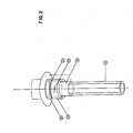
- - la figure 2 est une vue en perspective du mécanisme de suspension du tube de poche de coulée.
- En référence aux figures, des repères identiques représentent des éléments identiques ou analogues.
- Le dispositif de commande d'un tube de poche de coulée, selon la présente invention, est constitué d'un bras 1 supporté, en son milieu par une genouillère universelle 3 permettant une rotation suivant un axe vertical 5, un axe horizontal 7 et suivant l'axe même dudit bras, permettant ainsi l'inclinaison latérale du tube de poche de coulée située au bout dudit bras. La genouillère 3 supportant ledit bras est elle-même supportée par une potence 9 fixée au plancher de coulée moyennant un pivot 11. On obtient ainsi une multitude de mouvements qui permettent de balayer une zone plus vaste avec le tube de poche de coulée.
- Une extrémité du bras est munie d'un. contre- poids 13 qui permet d'obtenir, en plus de l'équilibre du tube, un effort vertical vers le haut appliquant le tube de poche sur la busette du tiroir avec un effort suffisant pour assurer l'étanchéité à l'emboîtement entre le col du tube connu en soi et le nez de la busette du tiroir de coulée. Le contre-poids est rendu déplaçable le long de l'arbre à l'aide d'une vis mue par un moto-réducteur 15. L'usage d'un contre- poids permet également de remplir un effet d'application constant, après réglage, quelle que soit la hauteur de la poche dans le cas où la poche est posée sur un tourniquet du type levant par exemple.
- En absence d'énergie électrique ou pneumatique, le contre-poids permet également de conserver une force d'application intacte du tube de poche de coulée sur le tiroir de coulée ce qui constitue une sécurité essentielle en présence d'acier liquide en cours de coulée.
- Les diverses combinaisons de mouvements décrites ci-dessus permettent le chargement du tube de poche de coulée sur son dispositif de suspension, de le manutentionner depuis le plancher jusqu'à la poche de coulée dont la position XY peut être variable ainsi que son assiette et son altitude. En outre, lors de l'opération du tiroir de poche, le dispositif de commande selon la présente invention permet au tube de poche de coulée de suivre le tiroir dans toutes ses excursions, tout en gardant permanentes la connexion et l'étanchéité.
- Avantageusement les divers mouvements du dispositif selon la présente invention sont obtenus par des boutons poussoirs 17 et 18 installés sur la poignée de commande en bout de bras.
- L'extrémité opposée du bras comporte un étrier 19 dont chaque branche est munie d'un logement 21 pour un pivot 23 solidaire d'un anneau 25. Ledit anneau 25 supporte, par l'intermédiaire de billes 27, une bague mobile 29 sur laquelle s'appuie le tube de poche de coulée 31 connu en soi.
- L'agencement selon la présente invention permet au tube de poche de coulée de rester constamment aligné sur la busette du tiroir et permet sa rotation relative par rapport à l'étrier durant tous les déplacements du tiroir en manoeuvre.
- Un autre avantage du dispositif de suspension selon présente invention réside dans la réduction du frottement entre l'étrier et le tube, lors de l'opération du tiroir, même en présence de températures très élevées auxquelles est soumis le dispositif de suspension décrit et ce, tout en conservant une bonne stabilité de fonctionnement et une durée de vie acceptable. Avantageusement, en vue d'assurer la stabilité dimensionnelle du dispositif de suspension selon l'invention, celui-ci est avantageusement refroidi, par convection naturelle ou par un jet d'air comprimé. Avantageusement, le dispositif de suspension est protégé par un écran 33 qui empêche la pénétration des projections et de gouttelettes d'acier, de scories ou d'un autre métal liquide de pénétrer dans le dispositif de suspension.
Claims (7)
Priority Applications (1)
| Application Number | Priority Date | Filing Date | Title |
|---|---|---|---|
| AT87870073T ATE52434T1 (de) | 1986-06-17 | 1987-05-21 | Vorrichtung zur steuerung des auslassrohres einer giesspfanne. |
Applications Claiming Priority (2)
| Application Number | Priority Date | Filing Date | Title |
|---|---|---|---|
| BE6/48231A BE904940A (fr) | 1986-06-17 | 1986-06-17 | Dispositif de commande d'un tube de poche de coulee. |
| BE6048231 | 1986-06-17 |
Publications (3)
| Publication Number | Publication Date |
|---|---|
| EP0250387A2 EP0250387A2 (fr) | 1987-12-23 |
| EP0250387A3 EP0250387A3 (en) | 1988-03-23 |
| EP0250387B1 true EP0250387B1 (fr) | 1990-05-09 |
Family
ID=3874996
Family Applications (1)
| Application Number | Title | Priority Date | Filing Date |
|---|---|---|---|
| EP87870073A Expired - Lifetime EP0250387B1 (fr) | 1986-06-17 | 1987-05-21 | Dispositif de commande d'un tube de poche de coulée |
Country Status (2)
| Country | Link |
|---|---|
| EP (1) | EP0250387B1 (fr) |
| AT (1) | ATE52434T1 (fr) |
Family Cites Families (4)
| Publication number | Priority date | Publication date | Assignee | Title |
|---|---|---|---|---|
| US4381102A (en) * | 1979-10-29 | 1983-04-26 | Flo-Con Systems, Inc. | Shroud support and method for shroud engagement with teeming valve |
| US4316561A (en) * | 1980-08-05 | 1982-02-23 | United States Steel Corporation | Pour tube latching apparatus |
| DE3425676C2 (de) * | 1984-06-19 | 1986-10-09 | Stopinc Ag, Baar | Vorrichtung zum Auswechseln eines Gießrohres |
| DE3426894C2 (de) * | 1984-07-20 | 1986-08-28 | Handhabungsgeräte für Stahlwerke GmbH, 6612 Schmelz | Handhabungsgeräte zum Manipulieren von Schattenrohren |
-
1987
- 1987-05-21 EP EP87870073A patent/EP0250387B1/fr not_active Expired - Lifetime
- 1987-05-21 AT AT87870073T patent/ATE52434T1/de not_active IP Right Cessation
Also Published As
| Publication number | Publication date |
|---|---|
| EP0250387A3 (en) | 1988-03-23 |
| ATE52434T1 (de) | 1990-05-15 |
| EP0250387A2 (fr) | 1987-12-23 |
Similar Documents
| Publication | Publication Date | Title |
|---|---|---|
| CA2332472A1 (fr) | Organe de prehension orientable pour le transport ou l'usinage d'une piece de forme quelconque | |
| EP0048641A1 (fr) | Protection d'un métal en fusion dans un obturateur à plaques | |
| FR2578472A1 (fr) | Perfectionnements aux robots industriels du type a structure spherique | |
| KR102151852B1 (ko) | 주물 래들용 로봇암 | |
| WO1991003339A1 (fr) | Dispositif de coulee obturable pour un conteneur siderurgique ou metallurgique | |
| EP0331663A3 (fr) | Mécanisme de centrage automatique de disques | |
| US4316561A (en) | Pour tube latching apparatus | |
| US5271033A (en) | Induction furnace for melting and casting substances in a nonreactive atmosphere | |
| WO2000020647A1 (fr) | Dispositif de repartition de matieres en vrac | |
| FR2515406A1 (fr) | Manipulateur pour reacteur nucleaire | |
| EP0250387A2 (fr) | Dispositif de commande d'un tube de poche de coulée | |
| BE904940A (fr) | Dispositif de commande d'un tube de poche de coulee. | |
| FR2565861A1 (fr) | Dispositif permettant le remplacement d'un tube de coulee a raccorder a l'obturateur de coulee d'un recipient metallurgique | |
| FR2695847A1 (fr) | Appareil pour ouvrir et fermer une ouverture de coulée. | |
| EP0124394B1 (fr) | Dispositif de manoeuvre d'un élément de carrosserie pivotant | |
| FR2576229A3 (fr) | Machine de compression de boites vides | |
| LU87082A1 (fr) | Dispositif d'accouplement d'une poche metallurgique a un reseau de gaz | |
| FR2552506A1 (fr) | Dispositif de palier pour arbre pouvant prendre une inclinaison | |
| JPH0138592B2 (fr) | ||
| FR2478251A2 (fr) | Dispositif d'obturation d'une conduite de gaz a section elevee | |
| FR2562448A1 (fr) | Dispositif de manipulation d'un tube de protection d'un jet de coulee | |
| EP0498684B1 (fr) | Dispositif d'éjection de support de tube protecteur de jet dans une installation de coulée continue | |
| FR2586210A1 (fr) | Dispositif de protection contre l'oxydation et/ou la nitruration d'un jet de metal liquide et son utilisation | |
| FR2429062A1 (fr) | Dispositif de prelevement, de transfert et de coulee d'un metal en fusion | |
| EP0455619B1 (fr) | Dispositif pour la coulée d'un métal et procédé d'utilisation |
Legal Events
| Date | Code | Title | Description |
|---|---|---|---|
| PUAI | Public reference made under article 153(3) epc to a published international application that has entered the european phase |
Free format text: ORIGINAL CODE: 0009012 |
|
| AK | Designated contracting states |
Kind code of ref document: A2 Designated state(s): AT CH DE ES FR GB GR IT LI LU NL SE |
|
| PUAL | Search report despatched |
Free format text: ORIGINAL CODE: 0009013 |
|
| AK | Designated contracting states |
Kind code of ref document: A3 Designated state(s): AT CH DE ES FR GB GR IT LI LU NL SE |
|
| 17P | Request for examination filed |
Effective date: 19880915 |
|
| 17Q | First examination report despatched |
Effective date: 19890220 |
|
| GRAA | (expected) grant |
Free format text: ORIGINAL CODE: 0009210 |
|
| AK | Designated contracting states |
Kind code of ref document: B1 Designated state(s): AT CH DE ES FR GB GR IT LI LU NL SE |
|
| PG25 | Lapsed in a contracting state [announced via postgrant information from national office to epo] |
Ref country code: GR Free format text: LAPSE BECAUSE OF FAILURE TO SUBMIT A TRANSLATION OF THE DESCRIPTION OR TO PAY THE FEE WITHIN THE PRESCRIBED TIME-LIMIT Effective date: 19900509 |
|
| REF | Corresponds to: |
Ref document number: 52434 Country of ref document: AT Date of ref document: 19900515 Kind code of ref document: T |
|
| PG25 | Lapsed in a contracting state [announced via postgrant information from national office to epo] |
Ref country code: LI Effective date: 19900531 Ref country code: CH Effective date: 19900531 |
|
| GBT | Gb: translation of ep patent filed (gb section 77(6)(a)/1977) | ||
| REF | Corresponds to: |
Ref document number: 3762580 Country of ref document: DE Date of ref document: 19900613 |
|
| ITF | It: translation for a ep patent filed | ||
| PG25 | Lapsed in a contracting state [announced via postgrant information from national office to epo] |
Ref country code: ES Free format text: LAPSE BECAUSE OF FAILURE TO SUBMIT A TRANSLATION OF THE DESCRIPTION OR TO PAY THE FEE WITHIN THE PRESCRIBED TIME-LIMIT Effective date: 19900820 |
|
| REG | Reference to a national code |
Ref country code: CH Ref legal event code: PL |
|
| PLBE | No opposition filed within time limit |
Free format text: ORIGINAL CODE: 0009261 |
|
| STAA | Information on the status of an ep patent application or granted ep patent |
Free format text: STATUS: NO OPPOSITION FILED WITHIN TIME LIMIT |
|
| 26N | No opposition filed | ||
| ITTA | It: last paid annual fee | ||
| PGFP | Annual fee paid to national office [announced via postgrant information from national office to epo] |
Ref country code: FR Payment date: 19940422 Year of fee payment: 8 |
|
| PGFP | Annual fee paid to national office [announced via postgrant information from national office to epo] |
Ref country code: GB Payment date: 19940429 Year of fee payment: 8 |
|
| PGFP | Annual fee paid to national office [announced via postgrant information from national office to epo] |
Ref country code: LU Payment date: 19940430 Year of fee payment: 8 |
|
| PGFP | Annual fee paid to national office [announced via postgrant information from national office to epo] |
Ref country code: AT Payment date: 19940511 Year of fee payment: 8 |
|
| PGFP | Annual fee paid to national office [announced via postgrant information from national office to epo] |
Ref country code: DE Payment date: 19940517 Year of fee payment: 8 |
|
| PGFP | Annual fee paid to national office [announced via postgrant information from national office to epo] |
Ref country code: SE Payment date: 19940526 Year of fee payment: 8 |
|
| PGFP | Annual fee paid to national office [announced via postgrant information from national office to epo] |
Ref country code: NL Payment date: 19940531 Year of fee payment: 8 |
|
| EPTA | Lu: last paid annual fee | ||
| EAL | Se: european patent in force in sweden |
Ref document number: 87870073.1 |
|
| PG25 | Lapsed in a contracting state [announced via postgrant information from national office to epo] |
Ref country code: LU Free format text: LAPSE BECAUSE OF NON-PAYMENT OF DUE FEES Effective date: 19950521 Ref country code: GB Effective date: 19950521 Ref country code: AT Effective date: 19950521 |
|
| PG25 | Lapsed in a contracting state [announced via postgrant information from national office to epo] |
Ref country code: SE Effective date: 19950522 |
|
| PG25 | Lapsed in a contracting state [announced via postgrant information from national office to epo] |
Ref country code: NL Effective date: 19951201 |
|
| GBPC | Gb: european patent ceased through non-payment of renewal fee |
Effective date: 19950521 |
|
| NLV4 | Nl: lapsed or anulled due to non-payment of the annual fee |
Effective date: 19951201 |
|
| PG25 | Lapsed in a contracting state [announced via postgrant information from national office to epo] |
Ref country code: DE Effective date: 19960201 |
|
| EUG | Se: european patent has lapsed |
Ref document number: 87870073.1 |
|
| PG25 | Lapsed in a contracting state [announced via postgrant information from national office to epo] |
Ref country code: FR Effective date: 19960229 |
|
| REG | Reference to a national code |
Ref country code: FR Ref legal event code: ST |
|
| REG | Reference to a national code |
Ref country code: FR Ref legal event code: ST |
|
| PG25 | Lapsed in a contracting state [announced via postgrant information from national office to epo] |
Ref country code: IT Free format text: LAPSE BECAUSE OF NON-PAYMENT OF DUE FEES Effective date: 20050521 |