EP0250102A2 - Zerstäubungsvorrichtung und -verfahren - Google Patents
Zerstäubungsvorrichtung und -verfahren Download PDFInfo
- Publication number
- EP0250102A2 EP0250102A2 EP87304545A EP87304545A EP0250102A2 EP 0250102 A2 EP0250102 A2 EP 0250102A2 EP 87304545 A EP87304545 A EP 87304545A EP 87304545 A EP87304545 A EP 87304545A EP 0250102 A2 EP0250102 A2 EP 0250102A2
- Authority
- EP
- European Patent Office
- Prior art keywords
- liquid
- spraying
- droplets
- site
- flight
- Prior art date
- Legal status (The legal status is an assumption and is not a legal conclusion. Google has not performed a legal analysis and makes no representation as to the accuracy of the status listed.)
- Ceased
Links
Images

Classifications
-
- B—PERFORMING OPERATIONS; TRANSPORTING
- B22—CASTING; POWDER METALLURGY
- B22F—WORKING METALLIC POWDER; MANUFACTURE OF ARTICLES FROM METALLIC POWDER; MAKING METALLIC POWDER; APPARATUS OR DEVICES SPECIALLY ADAPTED FOR METALLIC POWDER
- B22F9/00—Making metallic powder or suspensions thereof
- B22F9/02—Making metallic powder or suspensions thereof using physical processes
- B22F9/14—Making metallic powder or suspensions thereof using physical processes using electric discharge
-
- B—PERFORMING OPERATIONS; TRANSPORTING
- B05—SPRAYING OR ATOMISING IN GENERAL; APPLYING FLUENT MATERIALS TO SURFACES, IN GENERAL
- B05B—SPRAYING APPARATUS; ATOMISING APPARATUS; NOZZLES
- B05B5/00—Electrostatic spraying apparatus; Spraying apparatus with means for charging the spray electrically; Apparatus for spraying liquids or other fluent materials by other electric means
- B05B5/025—Discharge apparatus, e.g. electrostatic spray guns
- B05B5/0255—Discharge apparatus, e.g. electrostatic spray guns spraying and depositing by electrostatic forces only
-
- B—PERFORMING OPERATIONS; TRANSPORTING
- B05—SPRAYING OR ATOMISING IN GENERAL; APPLYING FLUENT MATERIALS TO SURFACES, IN GENERAL
- B05B—SPRAYING APPARATUS; ATOMISING APPARATUS; NOZZLES
- B05B5/00—Electrostatic spraying apparatus; Spraying apparatus with means for charging the spray electrically; Apparatus for spraying liquids or other fluent materials by other electric means
- B05B5/08—Plant for applying liquids or other fluent materials to objects
- B05B5/087—Arrangements of electrodes, e.g. of charging, shielding, collecting electrodes
Definitions
- This invention relates to apparatus and a process for spraying liquids capable of wholly or partly curing.
- apparatus for spraying liquids which can be wholly or partly cured to produce particles or coatings, comprising: an electrostatic spray head having a spraying site, an electrically conducting or semiconducting liquid contacting surface and means for delivering the said liquid to the spraying site; high voltage supply means for charging the liquid contacting surface to a high voltage of one polarity relative to a reference surface, said voltage being sufficiently high and in combination the spraying site being sufficiently sharp, as to intensify the electric field strength at the spraying site sufficiently when covered, in use, by the liquid being sprayed, that the liquid at the spraying site is drawn out preponderantly by electrostatic forces into at least one cone from which a corresponding ligament issues and breaks up into electrically charged droplets; and means for treating the droplets in flight to initiative curing.
- Initiating curing in flight can significantly reduce cure times. There are several effects which can contribute. Compared with initiating curing when the droplets have deposited on a target, there is a small time advantage in initiating curing in flight. The liquid sprayed is more finely divided as droplets in flight, than it would be as a coating on a target, so the treatment is effective over a larger surface of the liquid. Compared with initiating curing before spraying there can be an advantage in the possibility of using a faster chemical system which might cause problems by curing inside conventional spraying apparatus. The use of the electrostatic field to produce the ligaments enables the droplets to be produced of closely similar size. This ensures that the liquid is all treated substantially equally. If the droplet size differed greatly, the liquid in larger droplets would receive less treatment than _smaller droplets.
- a process for spraying liquids which can be wholly or partly cured to produce particles or coatings, comprising: delivering said liquid to a spraying site of an electrostatic spray head, making electrical contact with said liquid via an electrically . conducting or semiconducting liquid contacting surface; charging the liquid contacting surface to a high voltage of one polarity relative to a reference surface, to intensify the electric field strength at the spraying site sufficiently that the liquid at the spraying site is drawn out preponderantly by electrostatic forces into at feast one cone from-which a corresponding ligament issues and breaks up into electrically charged droplets; and treating the droplets in flight to initiate curing.
- the curing reaction is initiated while the composition in spray form is in flight towards a target object.
- the extent to which the reaction takes place depends upon the rate of the reaction, the speed of flight and the distance to the target object.
- the conditions are chosen so that curing will proceed to such an extent that the composition can still flow to form a film on the target. the curing reaction can be accelerated by heating.
- the apparatus has an electrostatic spray head 2.
- the spray head is shown in more detailed cross section in Figure 2.
- the spray head is linear, having a generally constant cross section.
- the spray head is made largely of insulating material.
- Liquid to be sprayed is supplied via one or more channels 10 to a gallery 12.
- the liquid may be clear or may contain pigment or other matter.
- the gallery 12 distributes liquid to a slot 14 communicating with the centre of a spraying site in the form of an edge 16.
- the slot naturally, has two sides, the electrostatic effect is that of one edge. That is to say only one set of ligaments is formed centrally. If the effect were that of two edges, ligaments would be produced off the "edges" at both sides of the slot. This concept of one edge fed by a central slot may, perhaps, be better understood by considering that the liquid to be sprayed has significant conductivity and will, in use, bridge the slot.
- the conducting or semiconducting surface 18 is connected via a high voltage supply lead 20, to one of the high voltage output terminals 22 of a high voltage generator 24.
- Another output terminal 26 of the high voltage generator is connected to a reference surface 28' on which the article to be sprayed is placed.
- the electric field is defined between the reference surface and the- liquid arriving at the edge 16.
- the edge 16. is sharp to a degree sufficient, in combination with the voltage produced by the high voltage generator, to define an intense electrical field. Assuming the surface 18 has a positive potential relative to the reference surface, negative charge is conducted away from the liquid at its contact with the conducting or semiconducting surface, leaving a net positive charge on the liquid.
- the electric field at the liquid/air boundary at the edge 16 is sufficiently intense that the liquid is drawn out into ligaments spaced along the edge 16.
- the liquid becomes positively charged, negative charge being conducted away by the conducting surface 18, leaving a net positive charge on the liquid.
- the charge on the liquid produces internal repulsive electrostatic forces which overcomes the surface tension of the liquid, forming cones of liquid at spaced intervals along the edge 16. From the tip of each cone a ligament issues. At a distance from the edge 16, mechanical forces produced by travelling through the air cause it to break up into charged droplets of closely similar size.
- the number of ligaments which is formed depends on the flow rate of the liquid and on the electric field intensity, amongst other factors such as the resistivity and the viscosity of the liquid. All other things being constant, controlling the voltage and the flow rate, controls the number of ligaments, which enables the droplet size to be controlled and very closely similar, say 40 to 50 microns.
- the distance between the edge 16 and the conducting or semiconducting surface 8 ⁇ must therefore be sufficiently small to allow for the resistivity of the liquid being used.
- a suitable position can be found for the surface even when spraying, say, a liquid having a resistivity in the range of 10 6 to 10 10 ohm cm.
- the spray head 2 is directly into a chamber 30.
- Means is provided in the form of a source of ultra violet radiation 36, to treat the droplets in flight.
- the source 36 illuminates the droplets through a quartz window 34.
- the apparatus is used to coat an article, which is placed on the conducting surface 28 below the spray head 2, with the liquid coating in which the cure has already started as a result of the treatment in flight. Subsequent baking at elevated temperature may be used to accelerate the curing reaction.
- the electrostatic field between the spray head and the article causes the spray to wrap around the article to a subsequential degree, so that undersurfaces can be coated even when only sprayed from above.
- the spray head could be made portable, however, to increase accessibility of, say undersides and to improve the evenness of the coating.
- the source of ultraviolet radiation may remain fixed if that would still enable the droplets to be exposed in flight.
- the source 36 could be mounted on and mobile with the spray head 2.
- the source 36 may be replaced with a source of other electromagnetic radiation or with a - means of mixing a gas or vapour catalyst with the droplets in fligbt.
- the liquid comprised a mixture of N-viny pyrolidone 88%, benzophenone 4%, Irgacure 184 4% and dimethylethanolamine 4%.
- the mixture is found to cure quickly to form a dry surface when exposed to ultraviolet radiation.
- the walls 32 of the chamber 30 include a quartz window 34.
- the source 36 of ultra violet radiation is arranged to illuminate the inside of the chamber 30 through the window 34. If the liquid being sprayed cures very ' fast, it may be necessary to shield the ligaments from exposure to the ultraviolet.
- the ultraviolet source may be replaced with any suitable electromagnetic radiation source.e.g. visible light, infra red, micro wave, radio frequency etc.
- the spray head could be other than linear.
- the spray head could compris an arrangement to produce a single ligament such as a single conducting capillary tube.
- An alternative form to give a higher output is an annular spray head in which, say, Figure 2 is a section through one side of an annular ring.
- the reference surface may include a field adjusting electrode 38 positioned near the spray head.
- the electrode may be at the- same potential as the surface 28, as illustrated, or at some intermediate potential.
- a position, generally behind or level with the spraying edge 16, can be found at which virtually none of the liquid being sprayed deposits on it. Almost all the spray deposits as surface dry particles on the article 6 to be sprayed under the influence of the field between the spray head and the article.
- the electrode 38 would extend along both sides of and parallel to the spraying edge 16.
- the electrode 38 would be a ring surrounding the spray head.
- a gas or vapour catalyst is introduced into the chamber 30 via an inlet 56.
- An example of a chemical system suitable for this arrangement is a liquid epoxide sprayed from the spray head and air with a trace of BF 3 vapour introduced at the inlet 56.
- Examples of alternative catalysts in different systems are sulphur dioxide, oxygen, water vapour.
- Liquids which cure when catalyzed by water vapour include ketimines. In cases where atmospheric oxygen would act as an inhibitor, the air could be replaced by, say, nitrogen.
- the spray head has two slots 14a and 14b, one for each of the liquid components.
- the exits of the slots 14a and 14b lie parallel to but spaced from the spraying edge 16.
- the liquid component in each slot 14a and 14b passes over the surface 18a or 18b of a conducting or semiconducting strip which is connected to the output of the high voltage generator 24.
- the two liquid components leave the slots 14a and 14b and pass over exterior surfaces 58a and 58b where the components remain separated.
- the components only meet at the spraying edge where the cones . and ligaments which form contain both components. Although in the ligaments the components may not mix particularly well, when a droplet separates from a ligament it is thought to undergo several violent oscillations which mix the components. Whatever the explanation, the components are well enough mixed in the droplets to effect a cure.
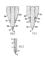
- the spray head illustrated in Figure 4 has its liquid contacting conducting or semiconducting surface at the edge 16. That is to say the edge 1.6 is formed in the conducting or semiconducting material
- three or more component liquids may be used, each liquid being fed to a common spraying edge, but only meeting the other components on the exterior of the spray head.
- a central slot in the spraying edge as in. Figure 2, could supply a third liquid component.
- Further liquid components could be provided via further slots over exterior surfaces 60a and 60b in Figures 3 and 4.
- the quality of the spray and the uniformity of the droplet size is sensitive to two factors amongst others.
- the number of ligaments formed depends on the field strength at the edge. Increasing the field strength increases the number of ligaments. Increasing the number of ligaments at the same overall flow rate, has the effect that each ligaments is finer so that the droplets it breaks up into are smaller.
- gas or vapour catalyst may disturb or destroy the ligaments on which the uniform droplet size relies.
- the sensitivity to these two factors may be reduced by use of a spray head having a spraying edge 16 formed with spaced tips as shown in Figure 5.
- the tips are provided in the example illustrated by teeth 72.
- the teeth 72 are formed in a body member 74 of insulating plastics material. Liquid to be sprayed is provided via an inlet (not illustrated) to a liquid distribution gallery 12 in the body 74.
- a closing plate 76 is spaced from and sealed to the body member 74 by a gasket 78.
- the gasket is open sided adjacent the teeth 72 defining a linear slot 14 between the body member 72 and the-closing plate 76.
- the gasket is so shaped as to provide channels 80 to supply liquid from the distribution gallery 12 to the slot 14.
- a conducting or semiconducting strip 18 is inset into the body member 42 to provide a liquid contracting surface.
- the strip 18 is connected to the high voltage output of a high voltage supply (not shown in Figure 6) to charge the liquid so that spraying takes place.
- a high voltage supply not shown in Figure 6
- the electric field strength at the tip of each tooth 72 is sufficient to produce a ligament, but the field strength between the teeth 72 is not sufficient to produce a ligament. This condition pertains over a wide range of voltages supplied by the high voltage generator, reducing the sensitivity of the droplet size to variations in voltage.
- each ligament is located at a particular physical point: the tip of a tooth, it is much less prone to disturbance by an air or gas stream passing the sprayhead.
Landscapes
- Electrostatic Spraying Apparatus (AREA)
- Application Of Or Painting With Fluid Materials (AREA)
Applications Claiming Priority (2)
| Application Number | Priority Date | Filing Date | Title |
|---|---|---|---|
| GB8614564 | 1986-06-16 | ||
| GB868614564A GB8614564D0 (en) | 1986-06-16 | 1986-06-16 | Spraying |
Publications (2)
| Publication Number | Publication Date |
|---|---|
| EP0250102A2 true EP0250102A2 (de) | 1987-12-23 |
| EP0250102A3 EP0250102A3 (de) | 1988-11-30 |
Family
ID=10599498
Family Applications (1)
| Application Number | Title | Priority Date | Filing Date |
|---|---|---|---|
| EP87304545A Ceased EP0250102A3 (de) | 1986-06-16 | 1987-05-21 | Zerstäubungsvorrichtung und -verfahren |
Country Status (8)
| Country | Link |
|---|---|
| EP (1) | EP0250102A3 (de) |
| JP (1) | JPS634867A (de) |
| AU (1) | AU7349087A (de) |
| CA (1) | CA1263061A (de) |
| GB (1) | GB8614564D0 (de) |
| NZ (1) | NZ220426A (de) |
| ZA (1) | ZA873936B (de) |
| ZW (1) | ZW10087A1 (de) |
Cited By (13)
| Publication number | Priority date | Publication date | Assignee | Title |
|---|---|---|---|---|
| WO1998003267A1 (en) * | 1996-07-23 | 1998-01-29 | Electrosols Ltd. | A dispensing device and method for forming material |
| US6252129B1 (en) | 1996-07-23 | 2001-06-26 | Electrosols, Ltd. | Dispensing device and method for forming material |
| EP1132980A2 (de) | 2000-03-06 | 2001-09-12 | Sel Semiconductor Energy Laboratory Co., Ltd. | Dünnschichtabscheidungsmethode für lichtemittierende Anordnungen |
| US6318640B1 (en) | 1992-12-01 | 2001-11-20 | Electrosols, Ltd. | Dispensing device |
| US6386195B1 (en) | 1992-12-22 | 2002-05-14 | Electrosols Ltd. | Dispensing device |
| US6595208B1 (en) | 1997-08-08 | 2003-07-22 | Battelle Memorial Institute | Dispensing device |
| US6753454B1 (en) | 1999-10-08 | 2004-06-22 | The University Of Akron | Electrospun fibers and an apparatus therefor |
| US7193124B2 (en) | 1997-07-22 | 2007-03-20 | Battelle Memorial Institute | Method for forming material |
| US7374774B2 (en) | 1999-08-31 | 2008-05-20 | Virginia Commonwealth University Intellectual Property Foundation | Electroprocessed material made by simultaneously electroprocessing a natural protein polymer and two synthetic polymers |
| US7615373B2 (en) | 1999-02-25 | 2009-11-10 | Virginia Commonwealth University Intellectual Property Foundation | Electroprocessed collagen and tissue engineering |
| US7759082B2 (en) | 1999-02-25 | 2010-07-20 | Virginia Commonwealth University Intellectual Property Foundation | Electroprocessed fibrin-based matrices and tissues |
| US7977527B2 (en) | 1996-07-23 | 2011-07-12 | Baltelle Memorial Institute | Dispensing device and method for forming material |
| WO2024030433A1 (en) * | 2022-08-02 | 2024-02-08 | Spraying Systems Co. | Narrow point electrostatic spray nozzle assembly and lubricant dispensing system |
Families Citing this family (3)
| Publication number | Priority date | Publication date | Assignee | Title |
|---|---|---|---|---|
| GB8617527D0 (en) * | 1986-07-17 | 1986-08-28 | Ici Plc | Spraying process |
| JP4676342B2 (ja) * | 2006-01-17 | 2011-04-27 | 九州日立マクセル株式会社 | 静電霧化器及び送風装置 |
| JP5092940B2 (ja) | 2008-07-01 | 2012-12-05 | 信越半導体株式会社 | 単結晶製造装置及び単結晶の製造方法 |
Family Cites Families (2)
| Publication number | Priority date | Publication date | Assignee | Title |
|---|---|---|---|---|
| US2695002A (en) * | 1950-06-24 | 1954-11-23 | Ransburg Electro Coating Corp | Electrostatic atomizer of liquids |
| GB8504254D0 (en) * | 1985-02-19 | 1985-03-20 | Ici Plc | Spraying apparatus |
-
1986
- 1986-06-16 GB GB868614564A patent/GB8614564D0/en active Pending
-
1987
- 1987-05-21 EP EP87304545A patent/EP0250102A3/de not_active Ceased
- 1987-05-25 NZ NZ220426A patent/NZ220426A/xx unknown
- 1987-05-28 AU AU73490/87A patent/AU7349087A/en not_active Abandoned
- 1987-06-01 ZW ZW100/87A patent/ZW10087A1/xx unknown
- 1987-06-02 ZA ZA873936A patent/ZA873936B/xx unknown
- 1987-06-11 CA CA000539460A patent/CA1263061A/en not_active Expired
- 1987-06-15 JP JP62147169A patent/JPS634867A/ja active Pending
Cited By (17)
| Publication number | Priority date | Publication date | Assignee | Title |
|---|---|---|---|---|
| US6318640B1 (en) | 1992-12-01 | 2001-11-20 | Electrosols, Ltd. | Dispensing device |
| US6386195B1 (en) | 1992-12-22 | 2002-05-14 | Electrosols Ltd. | Dispensing device |
| US6457470B1 (en) | 1992-12-22 | 2002-10-01 | Electrosols Ltd. | Dispensing device |
| WO1998003267A1 (en) * | 1996-07-23 | 1998-01-29 | Electrosols Ltd. | A dispensing device and method for forming material |
| US6252129B1 (en) | 1996-07-23 | 2001-06-26 | Electrosols, Ltd. | Dispensing device and method for forming material |
| US7977527B2 (en) | 1996-07-23 | 2011-07-12 | Baltelle Memorial Institute | Dispensing device and method for forming material |
| US7193124B2 (en) | 1997-07-22 | 2007-03-20 | Battelle Memorial Institute | Method for forming material |
| US6595208B1 (en) | 1997-08-08 | 2003-07-22 | Battelle Memorial Institute | Dispensing device |
| US7615373B2 (en) | 1999-02-25 | 2009-11-10 | Virginia Commonwealth University Intellectual Property Foundation | Electroprocessed collagen and tissue engineering |
| US7759082B2 (en) | 1999-02-25 | 2010-07-20 | Virginia Commonwealth University Intellectual Property Foundation | Electroprocessed fibrin-based matrices and tissues |
| US7374774B2 (en) | 1999-08-31 | 2008-05-20 | Virginia Commonwealth University Intellectual Property Foundation | Electroprocessed material made by simultaneously electroprocessing a natural protein polymer and two synthetic polymers |
| US6753454B1 (en) | 1999-10-08 | 2004-06-22 | The University Of Akron | Electrospun fibers and an apparatus therefor |
| US7564054B2 (en) | 2000-03-06 | 2009-07-21 | Semiconductor Energy Laboratory Co., Ltd. | Thin film forming device, method of forming a thin film, and self-light-emitting device |
| EP1132980A2 (de) | 2000-03-06 | 2001-09-12 | Sel Semiconductor Energy Laboratory Co., Ltd. | Dünnschichtabscheidungsmethode für lichtemittierende Anordnungen |
| EP1132980B1 (de) * | 2000-03-06 | 2012-05-09 | Semiconductor Energy Laboratory Co., Ltd. | Dünnschichtabscheidungsmethode für lichtemittierende Anordnungen |
| WO2024030433A1 (en) * | 2022-08-02 | 2024-02-08 | Spraying Systems Co. | Narrow point electrostatic spray nozzle assembly and lubricant dispensing system |
| US12551909B2 (en) | 2022-08-02 | 2026-02-17 | Spraying Systems | Narrow point electrostatic spray nozzle assembly and lubricant dispensing system |
Also Published As
| Publication number | Publication date |
|---|---|
| ZA873936B (en) | 1988-02-24 |
| JPS634867A (ja) | 1988-01-09 |
| CA1263061A (en) | 1989-11-21 |
| NZ220426A (en) | 1989-06-28 |
| AU7349087A (en) | 1987-12-17 |
| GB8614564D0 (en) | 1986-07-23 |
| ZW10087A1 (en) | 1989-01-18 |
| EP0250102A3 (de) | 1988-11-30 |
Similar Documents
| Publication | Publication Date | Title |
|---|---|---|
| EP0250102A2 (de) | Zerstäubungsvorrichtung und -verfahren | |
| US4801086A (en) | Spraying apparatus | |
| US4795330A (en) | Apparatus for particles | |
| EP0250164A2 (de) | Vorrichtung und Verfahren zur Herstellung von Pulvern und anderen granulatförmigen Stoffen | |
| US3408985A (en) | Electrostatic spray coating apparatus | |
| US4106697A (en) | Spraying device with gas shroud and electrostatic charging means having a porous electrode | |
| ES552175A0 (es) | Procedimiento y aparato para la pulverizacion electrostatica de liquidos. | |
| EP0085149B1 (de) | Verfahren und Vorrichtung zum elektrostatischen Auftragen von Flüssigkeiten oder Pulvern auf Stoffe oder Gegenstände | |
| EP0662866A1 (de) | Vorrichtung und verfahren zur elektrostatischen sprühbeschichtung. | |
| JPS57209664A (en) | Method of mixing and atomizing liquid | |
| DE10145131A1 (de) | Vorrichtung zum Erzeugen eines Aktivgasstrahls | |
| US7240861B2 (en) | Method and apparatus for dispensing paint powders for powder coatings | |
| FI76262C (fi) | Foerfarande och anordning foer sprutning av pulverpartiklar pao en yta, som skall oeverdragas elektrostatiskt. | |
| WO2002094455A1 (en) | Process for plasma treatment and apparatus | |
| EP3737506B1 (de) | Sprühdüsenanordnung und sprühwolkenformungsverfahren | |
| EP1264004B1 (de) | Verfahren und vorrichtung zur beschichtung von substraten | |
| US2826451A (en) | Spray device for electrostatic deposition of a fluid | |
| EP0230723A2 (de) | Apparat zum Laden von Pulver und elektrostatischer Pulverbeschichtungsapparat | |
| DE2749400C3 (de) | Elektrostatische Spritzeinrichtung mit Schutzgasummantelung | |
| SU1069864A2 (ru) | Устройство дл нанесени покрытий из дисперсных полимерных материалов | |
| SU1053888A1 (ru) | Устройство дл нанесени покрытий из дисперсных полимерных материалов | |
| RU1789293C (ru) | Электростатический распылитель | |
| JPS5939357A (ja) | 線状体用静電塗布装置 | |
| HK1004538B (en) | Spraying apparatus | |
| SU858933A2 (ru) | Распылитель дл электростатического нанесени порошковых покрытий |
Legal Events
| Date | Code | Title | Description |
|---|---|---|---|
| PUAI | Public reference made under article 153(3) epc to a published international application that has entered the european phase |
Free format text: ORIGINAL CODE: 0009012 |
|
| AK | Designated contracting states |
Kind code of ref document: A2 Designated state(s): AT BE CH DE ES FR GB IT LI NL SE |
|
| PUAL | Search report despatched |
Free format text: ORIGINAL CODE: 0009013 |
|
| AK | Designated contracting states |
Kind code of ref document: A3 Designated state(s): AT BE CH DE ES FR GB IT LI NL SE |
|
| 17P | Request for examination filed |
Effective date: 19890508 |
|
| 17Q | First examination report despatched |
Effective date: 19900510 |
|
| STAA | Information on the status of an ep patent application or granted ep patent |
Free format text: STATUS: THE APPLICATION HAS BEEN REFUSED |
|
| 18R | Application refused |
Effective date: 19901103 |
|
| RIN1 | Information on inventor provided before grant (corrected) |
Inventor name: NOAKES, TIMOTHY JAMES Inventor name: COLCLOUGH, MICHAEL LEONARD |