EP0249970A2 - Masque d'ombre pour tube image couleur, sa structure de support et procédé de fabrication d'un écran pour tube-image couleur - Google Patents
Masque d'ombre pour tube image couleur, sa structure de support et procédé de fabrication d'un écran pour tube-image couleur Download PDFInfo
- Publication number
- EP0249970A2 EP0249970A2 EP87108719A EP87108719A EP0249970A2 EP 0249970 A2 EP0249970 A2 EP 0249970A2 EP 87108719 A EP87108719 A EP 87108719A EP 87108719 A EP87108719 A EP 87108719A EP 0249970 A2 EP0249970 A2 EP 0249970A2
- Authority
- EP
- European Patent Office
- Prior art keywords
- mask
- apertures
- deposits
- center
- cathode ray
- Prior art date
- Legal status (The legal status is an assumption and is not a legal conclusion. Google has not performed a legal analysis and makes no representation as to the accuracy of the status listed.)
- Withdrawn
Links
Images

Classifications
-
- H—ELECTRICITY
- H01—ELECTRIC ELEMENTS
- H01J—ELECTRIC DISCHARGE TUBES OR DISCHARGE LAMPS
- H01J29/00—Details of cathode-ray tubes or of electron-beam tubes of the types covered by group H01J31/00
- H01J29/02—Electrodes; Screens; Mounting, supporting, spacing or insulating thereof
- H01J29/06—Screens for shielding; Masks interposed in the electron stream
- H01J29/07—Shadow masks for colour television tubes
-
- H—ELECTRICITY
- H01—ELECTRIC ELEMENTS
- H01J—ELECTRIC DISCHARGE TUBES OR DISCHARGE LAMPS
- H01J9/00—Apparatus or processes specially adapted for the manufacture, installation, removal, maintenance of electric discharge tubes, discharge lamps, or parts thereof; Recovery of material from discharge tubes or lamps
- H01J9/20—Manufacture of screens on or from which an image or pattern is formed, picked up, converted or stored; Applying coatings to the vessel
- H01J9/22—Applying luminescent coatings
- H01J9/227—Applying luminescent coatings with luminescent material discontinuously arranged, e.g. in dots or lines
- H01J9/2271—Applying luminescent coatings with luminescent material discontinuously arranged, e.g. in dots or lines by photographic processes
-
- H—ELECTRICITY
- H01—ELECTRIC ELEMENTS
- H01J—ELECTRIC DISCHARGE TUBES OR DISCHARGE LAMPS
- H01J29/00—Details of cathode-ray tubes or of electron-beam tubes of the types covered by group H01J31/00
- H01J29/02—Electrodes; Screens; Mounting, supporting, spacing or insulating thereof
- H01J29/06—Screens for shielding; Masks interposed in the electron stream
- H01J29/07—Shadow masks for colour television tubes
- H01J29/076—Shadow masks for colour television tubes characterised by the shape or distribution of beam-passing apertures
-
- H—ELECTRICITY
- H01—ELECTRIC ELEMENTS
- H01J—ELECTRIC DISCHARGE TUBES OR DISCHARGE LAMPS
- H01J9/00—Apparatus or processes specially adapted for the manufacture, installation, removal, maintenance of electric discharge tubes, discharge lamps, or parts thereof; Recovery of material from discharge tubes or lamps
- H01J9/20—Manufacture of screens on or from which an image or pattern is formed, picked up, converted or stored; Applying coatings to the vessel
- H01J9/22—Applying luminescent coatings
- H01J9/227—Applying luminescent coatings with luminescent material discontinuously arranged, e.g. in dots or lines
- H01J9/2271—Applying luminescent coatings with luminescent material discontinuously arranged, e.g. in dots or lines by photographic processes
- H01J9/2272—Devices for carrying out the processes, e.g. light houses
Definitions
- This invention concerns ultra-high resolution foil tension mask color cathode ray tubes, and more particularly, relates to an improved front assembly for such tubes which has a shadow mask with aperture configurations that provide for brightness uniformity and color purity throughout the picture area.
- the term "shadow mask” is a component of a color cathode ray tube located in spaced adjacency to the faceplate, one having a plurality of apertures for the passage of the electron beams that excite phosphors deposited on the screen of the faceplate.
- the shadow mask noted as having circular or near-circular apertures, "shadows” the triads of phosphor deposits so that the proper beam falls upon the assigned ones of the phosphor deposits.
- the shadow mask is also referred to as a "color selection electrode", or "parallax barrier”. Shadow masks that may benefit from the invention include the foil mask secured to a suitable mask support under high tension, as well as the conventional curved mask with its associated curved faceplate, as designed for ultra-high resolution.
- beamlet means that portion of a light beam, or an electron beam, upon passing through a mask aperture.
- a “light beamlet” is formed by ultraviolet light rays that irradiate the shadow mask during screening.
- An “electron beamlet” is formed by any one of the three electron beams which have their origin in a three-beam electron gun located in the neck of the cathode ray tube envelope.
- the term "light image” is that area of the screening surface upon which a light beamlet falls.
- a “beam spot” is the area upon which an electron beamlet falls.
- screening surface refers to the screening surface of the faceplate which, in the manufacturing process, receives successive layers of screening fluids, comprising the grille and the phosphor deposits.
- screening refers to the inner surface of the faceplate following the deposition of the grille and the respective phosphor deposits that emit red, green and blue light when excited to luminescence by electron beamlets.
- negative guard band means a condition in which the beam spots are larger than the target phosphor deposits by a predetermined guard band area.
- the margin of safety, or “guard band” that prevents color impurities conventionally comprises a light-absorbing material called the grille.
- clipping refers to the reduction in the radial width of a beamlet in passing through a shadow mask aperture at an angle, and in which the edges of the aperture intercept the light rays in photoscreening, or the electron beams during tube operation.
- the amount of clipping is a function of the thickness of the shadow mask and the angle at which the light rays or electrons approach the aperture. The thicker the mask and the greater the angle, the greater the clipping.
- U. S. Patent 2,947,899 discloses a compensated aperture mask structure having a plurality of apertures which are round at the axial aperture, but distorted into an elliptical configuration by radial foreshortening as a function of the distance of the apertures from the axial aperture.
- U. S. Patent 4,l39,797 discloses a system for increasing tolerance to radial registration errors between the electron beam landing areas and the phosphor elements due to shadow mask doming during operation of the tube.
- the geometry of the beam landing areas and the phosphor elements are characterized by having off the tube axis smaller ones of the phosphor elements and the mask apertures radially compressed relative to larger ones without a corresponding azimuthal compression.
- the radial compression increased with increasing radius such that the tolerances in the radial direction increase off axis without a corresponding increase in azimuthal tolerance.
- the result is said to be increased tolerance to the doming-induced registration errors between the phosphor elements and the beam landing areas.
- a general aim of the invention is to provide an ultra-high resolution color cathode ray tube in which the phosphor deposits on the screen, and the beam spots, are compatible in size and shape all over the screen.
- the present invention therefore provides a color cathode ray tube shadow mask characterized by having circular apertures at the mask center, and apertures at least in the mask periphery increasingly elongated radially outwardly as a function of distance from the center.
- a front assembly for ultra-high resolution color cathode ray tubes having a shadow mask which, when used for photoscreening in conjunction with the screening surface of the faceplate, forms phosphor deposits compatible in size and shape with the beam spots, especially on the periphery of the screen.
- the invention makes it possible to overcome the problems in photoscreening ultra-high resolution color cathode ray tubes having large deflection angles and shadow masks with very small apertures.
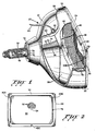
- Figure l depicts a color cathode ray tube 20 having a novel front assembly 22 according to the invention.
- the front assembly 22 includes a glass faceplate 24 noted as being flat, or alternatively, "substantially" flat in that it may have finite horizontal and vertical radii.
- Faceplate 24, depicted in this embodiment of the invention as being planar and flangeless, is represented as having on its inner surface a centrally disposed phosphor screen 28, on which is deposited an electrically conductive aluminum film 30.
- Screen 28 is surrounded by a peripheral sealing area 34 adapted to be mated with a funnel 32.
- Sealing area 36 preferably has three substantially radially oriented first indexing means in the form of V-grooved grooves 40A, 40B and 40C therein.
- the indexing grooves are preferably peripherally located at equal angular intervals about the center of the faceplate 24; that is, at l20-degree intervals as shown in Fig. 2.
- the V-shaped indexing grooves provide for indexing faceplate 24 in conjunection with a mating envelope member, as will be shown.
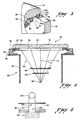
- Funnel 32 has a funnel sealing area 36 with second indexing means in the form of a cavity therein in like orientation, and in facing adjacency with each of the first indexing elements 40A, 40B and 40C.
- second indexing cavities or elements 44A is shown in Fig. 3 in cooperation with the first indexing element 40A.
- Complementary rounded indexing means forming a third indexing element are provided for cooperation with the first and second indexing means for registering the faceplate 24 and the funnel 32.
- the third indexing means comprises a ball 42A seated in groove 40A and cavity 44A.
- the first indexing elements together with the ball means are also utilized as indexing means during the photoscreening of the phosphor deposits on the faceplate 24.
- Front assembly 22 includes a separate faceplate-mounted shadow mask support structure 48 in the form of metal frame secured to the inner surface of faceplate 24 between the screen 28 and the peripheral sealing area 26 of faceplate 24 and enclosing the phosphor screen 28.
- the separate faceplate-mounted metal frame 48 according to the invention provides for supporting a welded-on tension foil apertured shadow mask 50 a predetermined "Q" distance from the inner surface of faceplate 24.
- the mask indicated as being planar, is depicted as being stretched in all directions in the plane of the mask.
- the enlarged inset in Fig. 2 depicts the apertures 52 in the shadow mask 50 adjacent the center 54 of the mask 50 as being of generally circular form.
- the metal faceplate support structure 50 which is preferably made of ceramic may for example be attached to the inner surface of the faceplate 24 by devitrifying glass frit 46 well-known in the art, or by a cold-setting cement such as a Sauereisen-type cement.
- a neck 66 extending from funnel 32 is represented as housing an electron gun 68 which is indicated as emitting three electron beams 70, 72 and 74 that selectively activate the screen 28, noted as comprising colored-light emitting phosphor deposits overlayed with the conductive film 30. Beams 70, 72 and 74 serve to selectively activate the pattern of phosphor deposits after passing through the parallax barrier formed by shadow mask 50.
- Funnel 32 is indicated as having an internal electrically conductive funnel coating 60 adapted to receive a high electrical potential.
- the potential is depicted as being applied through an anode button 62 attached to a conductor 64 which conducts a high electrical potential to the anode button 62 through the wall of the funnel 32.
- the source of the potential is a high-voltage power supply (not shown).
- the potential may be for example in the range of l8 to 26 kilovolts in the illustrated monitor application.
- Means for providing an electrical connection between the electrically conductive metal faceplate support structure 50 and the funnel coating 60 may comprise spring means 78.
- a magnetically permeable internal magnetic shield 58 is shown as being attached to support structure 50. Shield 58 extends into funnel 32 a predetermined distance which is calculated so that there is no inter ference with the excursion of the electron beams 70, 72 and 74, yet maximum shielding is provided.
- a yoke 76 is shown as encircling tube 20 in the region of the junction between funnel 32 and neck 66. Yoke 76 provides for the electromagnetic scanning of beams 70, 72 and 74 across the screen 28. The center axis 56 of tube 20 is indicated by the broken line.
- a black "grille” is initially deposited on the screening surface of the faceplate.
- a coating of a photo-sensitive material such as dichromated PVA (polyvinyl alcohol) is first deposited on the screening surface.
- the coating is then exposed to a light pattern through the shadow mask, which has been mounted a specified distance from the screening surface.
- the coating is developed to yield a pattern of dots whose distribution, size and shape correspond to the distribution, size and shape of the apertures in the shadow mask.
- the inner surface is covered with a layer of a light-absorptive material such as a slurry of graphite. The slurry is dried and becomes adherent.
- the photoscreening apparatus is termed a "lighthouse”; a typical lighthous 82 is depicted in figure 4.
- Lighthouse 82 is illustrated schematically as comprising a base 84 within which is contained a light source 86 of UV (ultraviolet) radiation, which is generated by a fine bare arc, typically an approximate point source when used for screening with shadow masks having circular apertures.
- Lighthouse 82 includes a table assembly 88 for receiving a screening assembly 90, which comprises a faceplate 9l, a shadow mask 92 and a shadow mask support structure 93, which supports and retains mask 92 a predetermined distance from the screening surface 94 of the faceplate 9l.
- Shadow mask 92 is depicted as being clamped by mask-stretching fixture 95, which exerts tension on the mask 92.
- the borders of the mask are shown as being clamped by clamping means 96.
- the faceplate 9l and the mask stretching fixture 95 are indicated as being held in precise registry by ball-and-groove indexing means 97 similar in form and function to the indexing means 38 described previously in connection with figures l-3.
- the screening assembly 90 is assembled and disassembled four times in the process of photoscreening the grille and the phosphor dots on the screening surface 94.
- the screening surface 94 receives the various screening fluids following successive exposures to ultraviolet radiation.
- the light rays l04 from point source 86 are depicted as irradiating the screening surface 94 after passing through a correction lens 99, a neutral density filter l00, and the apertures of the shadow mask 92.
- the shadow mask 92 still under tension, is permanently secured to the support structure 93 as by welding, and the remainder of the mask is cut away to release the screening assembly 90, which now becomes the front assembly, and to free the mask stretching fixture 95 for further use.
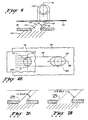
- the light rays l04 from the point source 86 of the lighthouse 82 in passing through the apertures of the shadow mask 92, approach the screening surface 94 more or less perpendicularly near the center of the mask 92.
- light rays l04 are shown as passing through a circular aperture l06 of the shadow mask 92 to form a light beamlet l07 which in turn forms a light image l08 on screening surface 94.
- the light image l08 on screening surface 94 is shown by the projection l09 of the light image l08 as being a round dot consonant in size and shape with the circular shadow mask aperture l06.
- the light rays l04 arrive at an angle of about 45 degrees or more in flat tension mask tubes having a wide deflection angle; this angle (not to scale) is indicated by reference number ll2 in figure 4.
- This condition is depicted in figure 6 wherein light rays l04 are shown as passing through an aperture ll0 to form light beamlet ll4.
- a projection ll6 of the light image ll7 formed by light beamlet ll4 on the screening surface 94 shows that the light image ll7 is in the form of an oval, with its major axis ll8 tangential.
- the oval shape is the result of the thickness of the mask 92 which "clips" the light rays l04, as indicated by the dashed lines lateral to and on either side of light beamlet ll4.
- the light beamlet ll4 formed in passing through aperture ll0, does not define on screening surface 94 a true light image of the oval aperture ll0 "seen" by light rays l04, but rather a light image l20 comprising an elongated oval whose major axis l22 lies in a radial direction with respect to the center of the mask.
- an electron beamlet when passing through aperture ll0 will produce an exact image of the aperture ll0 on the screening surface 94 as indicated by the beam spot l24 comprising a dashed-line oval, shown as being superimposed on oval pattern l20.
- the beam spot formed by the electron beamlet is distorted only by clipping. This lack of conformance of the untrue light image l20 formed by light beamlet ll4, and the truer image l24 formed by an electron beamlet, is intolerable in terms of effective shadow mask function.
- the undesirable effects include underexposure of the corner regions of the screen and placement of phosphors where there should be grille, leading to reduced contrast, or even overlapping of the phosphors, which in turn can cause color impurities.
- the undesired effect is attributable to the physical characteristics of shadow masks designed for use in ultra-high resolution displays.
- the foil tension mask described heretofore is a good example of such a mask.
- the apertures may be spaced, e.g. 8 mils apart center-to-center, and their diameter may be 3 mils.
- the mask may be l mil in thickness.
- the spacing (the "Q-distance") between mask and screen is typically 200 mils.
- Diffraction effects also occur in the near field. These effects are characterized by the opposite relationship, D/ ⁇ ⁇ (A/ ⁇ )2 These effects are known as Fresnel diffraction. They are more subtle and involve primarily a redistribution of light within the region that would normally be illuminated, with little light falling into the region which would normally be in shadow.
- a complete computation of the diffraction pattern produced by the circular apertures in the peripheral regions of the shadow mask would be quite lengthy.
- a useful approximation consists in replacing the circular aperture by a long slit of equal width, with its axis positioned tangentially with respect to the center of the faceplate.
- the diffraction patterns produced by slits can be calculated by standard methods: see for instance the book Introduction to Geometrical and Physical Optics, by Joseph Morgan, page 277 and appendix lE.
- the 45 degree angle of incidence causes clipping proportional to the mask thickness, which narrows the light beamlet radially; in addition, the effective radial width of the light beamlet ("W" in figure 6), is reduced by the cosine of the angle of incidence, so that the light beamlet which finally emerges from the 3 mil aperture is only l.4 mils wide, as indicated by figure 7A. Similarly, as shown by figure 7B, the light beamlet emerging from a 5 mil aperture is only 2.8 mils wide.
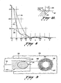
- the curves of figure 8 represent the light intensity distribution to the right of the center line of the projected pattern.
- the distribution is symmetrical, therefore only one side is plotted.
- the vertical scale indicates light intensity in terms of percent of that intensity which would exist if the aperture were very large.
- the upper horizontal scale gives the distance l25 from the center across the light beamlet measured in wavelengths of light.
- the lower horizontal scale provides the distance l26 from the center projected on the screening surface l27 in mils.
- the dash-dot curve l28 corresponds to the narrow, 3 mil slit shown by figure 7A, and represents actual intensity. It will be seen that the intensity at the center is nearly 50 percent; the distance between half power points is 3.6 mils, more than the original width of the slit and much wider than the light beamlet that actually passes through the slit. The distance between the two points where the intensity is ten percent of the peak is nearly 6 mils.
- the solid line curve l30 represents the wide slit shown in figure 7B.
- the intensity at the center is much higher--60 percent higher than the unperturbed intensity would be--and it drops to half its peak value at a point only 0.9 mils from the center line, giving a distance of l.8 mils between half-power points.
- the slit is now 5 mils wide, and even the tilted light beamlet emerging from the slit is nearly 3 mils wide.
- diffraction in this case has made the light beamlet considerably narrower than the slit, while in the first case it made it much wider.
- the unexpected problem presented by the diffraction of ultraviolet light in radially fore shortened apertures located in the mask periphery is resolved by the inventive means set forth herein.
- the shadow mask for the front assembly of an ultra-high resolution color cathode ray tube according to the invention is characterized by having apertures circular at the mask center, and apertures at least in the mask periphery increasingly elongated radially outwardly as a function of distance from the center.
- This configuration is depicted in part in figure 9 wherein a peripheral section of a shadow mask l32 according to the invention is indicated as being superimposed over a screening surface l34.
- Shadow mask l32 is shown as having an aperture l36 indicated as being elongated according to the invention with the major axis l38 of the elongation represented as being radially aligned; that is, aligned with a line extending from the mask center 54.
- the radial length of the aperture is greater than the tangential width to compensate for diffraction effects in the photoscreening process.
- Rays of ultraviolet light l40 are represented as passing through aperture l36, producing a light beamlet l42 which forms a near-circular image l44, and consequently, forms a round phosphor deposit on screening surface l34.
- the apertures at least in mask peripheral areas being increasingly elongated radially outwardly as a function of distance from the center according to the invention, UV-diffraction effects distortive to the phosphor deposits on the periphery of the screening surface during photoscreening are overcome.
- the elongation of the apertures according to the invention is effective to diminish the distortion of the deposits on the periphery and form deposits compatible in size and shape with the electron beamlets. This compatibility is indicated by figure 9 wherein light image l44 ( and the consequent phosphor deposit) is depicted as being compatible in size and shape with the beam spot l46, which is indicated by the dashed outline image of beam spot l46.
- Beam spot l46 will be noted as being slightly elongated in a radial direction; however, its contour will be seen as being compatible with the light image l44 (and the resulting phosphor deposit). The fact that the beam spot l46 does not exactly represent the contour of the aperture through which it passes is due to the aforedescribed "clipping" effect.
- the light-absorbing material that constitutes the grille l47 indicated diagrammatically by the stipple pattern around light image l44, represents a guardband effective to prevent color impurities.
- apertures l52A, l52B and l52C at least in mask peripheral areas are depicted as being increasingly elongated radially outwardly as a function of the distance from mask center l53.
- Diffraction effects are, of course, not limited to the radial dimension; they also occur along the tangential dimension of the mask apertures.
- the tangential dimension is not foreshortened either by clipping or by the cosine of the angle of incidence; therefore diffraction effects along the tangential axis are generally small and do not require the type of correction provided by the present invention.
- the tangential diffraction is neglected.
- a process or method according to the invention for use in the manufacture of an ultra-high resolution color cathode ray tube, and the photo-fabrication of the substantially flat faceplate of such a tube comprises the following.
- the tube may have a wide deflection angle.
- the process provides for photo-screening phosphor deposits on the screening surface (94) of the faceplate (9l) that are compatible in size and shape with the electron beam spots impinging the deposits.
- a phosphor compound sensitive to ultraviolet light is applied to the screening surface (94).
- a foil shadow mask (92) is provided that has apertures of such small dimension as to produce noticeable diffraction of ultraviolet light on the peripheral areas of the mask.
- the mask (92) has circular apertures at the mask center, and apertures at least in the mask periphery increasingly elongated radially outwardly as a function of distance from the mask center.
- the mask is suspended in tension at a predetermined distance from the screening surface (94), and the screening surface is exposed to ultraviolet light.
- the phosphor compound is developed to produce the phosphor deposits.
- the elongation of the apertures according to the inventive process is effective to reduce or eliminate ultraviolet light diffraction effects, and form phosphor deposits compatible in size and shape with the beam spots.
- the invention is applicable to the color cathode ray tube l56 depicted in figure ll, which will be readily recognized as the type having a conventional curved faceplate l58.
- Faceplate l58 of the front assembly l60 has a screening surface l62 for receiving deposits of phosphor (not indicated) that are excitable to luminescence by electron beamlets which have their origin in three electron beams l64 projected by electron gun l66.
- the deposits of phosphor are deposited by photoscreening with UV light.
- the front assembly includes a curved shadow mask l68 indicated as being suspended a predetermined distance from screening surface l62.
- the means of suspension l58 of shadow mask l68 may be by three springs selectively spaced about the periphery of the mask; one of the springs, spring l70 (representative of all three springs), is shown as being attached to the rigid frame l72 that supports shadow mask l68.
- An aperture l74 in an extension from spring l70 is engaged by a stud (not shown) that projects from the inner surface of the skirt l76 of tube l56.
- Shadow mask l68 is indicated hightly schematically as having, according to the invention, circular apertures at the mask center l78, and apertures at least in peripheral areas l80 of mask l68, which will be noted as being elongated radially outwardly as a function of distance from the center l78. It is observed that tube l56 is to be considered an ultra-high resolution tube in that it has apertures of a small diameter effective to produce the desired high resolution; that is, aperture diameters of about 3 mils.
- Such small aperture diameters which are about half the diameter of the apertures of a standard curved screen/curved mask tube, are noted as being susceptible to UV-diffraction effects distortive to the phosphor deposits in peripheral areas--effects resolved by the present invention.
- the undesired UV-diffraction effect is also aggravated by a wide deflection angle.
- the benefits of the invention can also be extended to a type of color cathode ray tube known as the "flat-square" tube.
- the type of tube has a faceplate that is relatively flat, with square corners.
- the correlatively flat shadow mask does not have the inherent strength of the curved mask of the tube shown by figure ll; in consequence, the mask must be made much thicker--of the order of l2 mils, by way of example.
- the apertures must be small.
- the relatively thick shadow mask may then be susceptible, at least on peripheral areas of the screening surface, to the UV-diffraction effects described in this disclosure in that the thickness of the metal of the mask, and the small aperture diameter required for ultra-high resolution, results in greater beam clipping. Clipping in turn causes the apertures in the periphery of the mask to appear as slits to the ultraviolet light rays in photoscreening, which, as has been described, produce the UV-diffraction effects distortive to the phosphor deposits.
Landscapes
- Engineering & Computer Science (AREA)
- Manufacturing & Machinery (AREA)
- Electrodes For Cathode-Ray Tubes (AREA)
- Cathode-Ray Tubes And Fluorescent Screens For Display (AREA)
- Formation Of Various Coating Films On Cathode Ray Tubes And Lamps (AREA)
Applications Claiming Priority (2)
| Application Number | Priority Date | Filing Date | Title |
|---|---|---|---|
| US875123 | 1986-06-17 | ||
| US06/875,123 US4745329A (en) | 1986-06-17 | 1986-06-17 | Front assembly for an ultra-high resolution color cathode ray tube having an improved shadow mask compensated for diffraction and process therefor |
Publications (2)
| Publication Number | Publication Date |
|---|---|
| EP0249970A2 true EP0249970A2 (fr) | 1987-12-23 |
| EP0249970A3 EP0249970A3 (fr) | 1988-11-09 |
Family
ID=25365237
Family Applications (1)
| Application Number | Title | Priority Date | Filing Date |
|---|---|---|---|
| EP87108719A Withdrawn EP0249970A3 (fr) | 1986-06-17 | 1987-06-16 | Masque d'ombre pour tube image couleur, sa structure de support et procédé de fabrication d'un écran pour tube-image couleur |
Country Status (5)
| Country | Link |
|---|---|
| US (1) | US4745329A (fr) |
| EP (1) | EP0249970A3 (fr) |
| JP (1) | JPS6345741A (fr) |
| KR (1) | KR880001019A (fr) |
| CN (1) | CN87104272A (fr) |
Cited By (3)
| Publication number | Priority date | Publication date | Assignee | Title |
|---|---|---|---|---|
| GB2226695A (en) * | 1988-11-26 | 1990-07-04 | Samsung Electronic Devices | Shadow mask for colour cathode ray tube |
| EP0409278B1 (fr) * | 1989-07-20 | 1997-01-15 | Sanyo Electric Co., Ltd. | Multivibrateur monostable |
| EP1367624A3 (fr) * | 2002-05-31 | 2005-03-30 | LG Philips Displays Korea Co., Ltd. | Masque d'ombre pour tube cathodique couleur |
Families Citing this family (2)
| Publication number | Priority date | Publication date | Assignee | Title |
|---|---|---|---|---|
| JPH07111877B2 (ja) * | 1987-09-10 | 1995-11-29 | 三菱電機株式会社 | 架張形シヤドウマスク |
| KR100545712B1 (ko) * | 1998-06-29 | 2006-05-23 | 엘지전자 주식회사 | 칼라음극선관용 섀도우마스크 |
Family Cites Families (7)
| Publication number | Priority date | Publication date | Assignee | Title |
|---|---|---|---|---|
| US2947899A (en) * | 1958-01-23 | 1960-08-02 | Zenith Radio Corp | Color image reproducers |
| US4139797A (en) * | 1977-07-01 | 1979-02-13 | Zenith Radio Corporation | Color television screen and shadow mask assembly having increased tolerance to radial registration errors |
| JPS5482966A (en) * | 1977-12-14 | 1979-07-02 | Mitsubishi Electric Corp | Exposure method for fluorescent screen of color braun tube |
| JPS54126458A (en) * | 1978-03-24 | 1979-10-01 | Nec Corp | Production of color picture tube fluorescent screen |
| JPS57132641A (en) * | 1981-02-12 | 1982-08-17 | Nec Corp | Shadow mask |
| JPS5916249A (ja) * | 1982-07-16 | 1984-01-27 | Mitsubishi Electric Corp | カラ−ブラウン管 |
| US4547696A (en) * | 1984-01-18 | 1985-10-15 | Zenith Electronics Corporation | Tension mask registration and supporting system |
-
1986
- 1986-06-17 US US06/875,123 patent/US4745329A/en not_active Expired - Lifetime
-
1987
- 1987-06-16 KR KR1019870006079A patent/KR880001019A/ko not_active Ceased
- 1987-06-16 EP EP87108719A patent/EP0249970A3/fr not_active Withdrawn
- 1987-06-17 JP JP62151029A patent/JPS6345741A/ja active Pending
- 1987-06-17 CN CN198787104272A patent/CN87104272A/zh active Pending
Cited By (4)
| Publication number | Priority date | Publication date | Assignee | Title |
|---|---|---|---|---|
| GB2226695A (en) * | 1988-11-26 | 1990-07-04 | Samsung Electronic Devices | Shadow mask for colour cathode ray tube |
| GB2226695B (en) * | 1988-11-26 | 1993-06-16 | Samsung Electronic Devices | Shadow mask for colour cathode ray tube |
| EP0409278B1 (fr) * | 1989-07-20 | 1997-01-15 | Sanyo Electric Co., Ltd. | Multivibrateur monostable |
| EP1367624A3 (fr) * | 2002-05-31 | 2005-03-30 | LG Philips Displays Korea Co., Ltd. | Masque d'ombre pour tube cathodique couleur |
Also Published As
| Publication number | Publication date |
|---|---|
| JPS6345741A (ja) | 1988-02-26 |
| US4745329A (en) | 1988-05-17 |
| CN87104272A (zh) | 1988-03-23 |
| EP0249970A3 (fr) | 1988-11-09 |
| KR880001019A (ko) | 1988-03-30 |
Similar Documents
| Publication | Publication Date | Title |
|---|---|---|
| US4547696A (en) | Tension mask registration and supporting system | |
| EP0239083B1 (fr) | Masque d'ombre plat pour tube image couleur | |
| US4078239A (en) | Method and apparatus for screening slot-mask, stripe screen color cathode ray tubes | |
| US4591344A (en) | Method of fabricating a tension mask color cathode ray tube | |
| EP0707335A1 (fr) | Dispositif d'affichage ayant une masque d'ombre avec résolution améliorée et sa procédé de fabrication | |
| EP0321202A1 (fr) | Tube à rayons cathodiques du type masques d'ombre | |
| US3882347A (en) | Color stripe cathode ray tube having bridged strip apertures | |
| EP0249970A2 (fr) | Masque d'ombre pour tube image couleur, sa structure de support et procédé de fabrication d'un écran pour tube-image couleur | |
| US4730143A (en) | Improved color cathode ray tube having a faceplate-mounted support structure with a welded-on high-tension foil shadow mask | |
| KR0141661B1 (ko) | 컬러음극선관 | |
| US3983613A (en) | Photographic master for use in making a color cathode ray tube shadow mask | |
| US4197482A (en) | Color selection means for color display tube and method of making same | |
| US4686416A (en) | Color CRT front assembly with tension mask support | |
| US6013400A (en) | Method of manufacturing a luminescent screen assembly for a cathode-ray tube | |
| US4849671A (en) | Color cathode ray tube having a faceplate-mounted support structure with a welded-on high-tension foil shadow mask | |
| EP0692810B1 (fr) | Tube à rayons cathodiques couleur | |
| US4778738A (en) | Method for producing a luminescent viewing screen in a focus mask cathode-ray tube | |
| US3790839A (en) | Rectangular grade black surround screen | |
| US4824412A (en) | Method for mounting a tension mask color cathode ray tube | |
| US3581136A (en) | Color dot screen with dot form compensation for apparent shift of beam deflection center | |
| CN88101395A (zh) | 彩色阴极射线管装置 | |
| US4983995A (en) | Exposure device for forming phosphor deposited screen in in-line cathode ray tube | |
| US3738233A (en) | Camera process for color tube screen printing | |
| JPH0139187B2 (fr) | ||
| US4111694A (en) | Method for manufacturing the picture display screen of a color television tube using a cylinder lens |
Legal Events
| Date | Code | Title | Description |
|---|---|---|---|
| PUAI | Public reference made under article 153(3) epc to a published international application that has entered the european phase |
Free format text: ORIGINAL CODE: 0009012 |
|
| AK | Designated contracting states |
Kind code of ref document: A2 Designated state(s): BE DE FR GB IT NL |
|
| PUAL | Search report despatched |
Free format text: ORIGINAL CODE: 0009013 |
|
| AK | Designated contracting states |
Kind code of ref document: A3 Designated state(s): BE DE FR GB IT NL |
|
| STAA | Information on the status of an ep patent application or granted ep patent |
Free format text: STATUS: THE APPLICATION IS DEEMED TO BE WITHDRAWN |
|
| 18D | Application deemed to be withdrawn |
Effective date: 19890510 |
|
| RIN1 | Information on inventor provided before grant (corrected) |
Inventor name: DIETCH, LEONARD |