EP0249864A2 - Relais piézo-électriques en boîtiers étanches - Google Patents
Relais piézo-électriques en boîtiers étanches Download PDFInfo
- Publication number
- EP0249864A2 EP0249864A2 EP87108359A EP87108359A EP0249864A2 EP 0249864 A2 EP0249864 A2 EP 0249864A2 EP 87108359 A EP87108359 A EP 87108359A EP 87108359 A EP87108359 A EP 87108359A EP 0249864 A2 EP0249864 A2 EP 0249864A2
- Authority
- EP
- European Patent Office
- Prior art keywords
- enclosure
- piezoceramic
- contacts
- relay
- bimorph member
- Prior art date
- Legal status (The legal status is an assumption and is not a legal conclusion. Google has not performed a legal analysis and makes no representation as to the accuracy of the status listed.)
- Withdrawn
Links
Images


Classifications
-
- H—ELECTRICITY
- H01—ELECTRIC ELEMENTS
- H01H—ELECTRIC SWITCHES; RELAYS; SELECTORS; EMERGENCY PROTECTIVE DEVICES
- H01H57/00—Electrostrictive relays; Piezoelectric relays
Definitions
- the present invention relates to piezoceramic relays and particularly to techniques for mounting and packaging the various parts of a piezoceramic relays.
- Electromagnetic relays are commonly used as switching components for controlling current flow in load circuits in response to control signals.
- Such relays are well suited to serve as an interface between, for example, an electronic control circuit and a load circuit, wherein the former handles the low power control signals for selectively energizing the relay coil to appropriately position the relay contacts acting in the power circuit to switch relatively higher levels of power.
- Electromagnetic relays do however have their drawbacks. Although they have been miniaturized as compared to earlier relay designs, their actuating power requirements are quite large in contrast to, for example, comparable, state of the art solid state power switches. Such relays are relatively complex and expensive to manufacture, for example, their coils typically require a large multitude of turns of very fine wire. The coil resistance, though low, nevertheless consumes some power with resulting generation of heat.
- electromagnetic relays can not be readily, reliably packaged in hermetic or vacuum sealed enclosures to provide a vacuum environment or an ambient atmosphere of an inert gas, such as nitrogen and argon, or of a high dielectric strength gas, such as sulfur hexaflouride, in which the relay contacts can operate.
- an inert gas such as nitrogen and argon
- a high dielectric strength gas such as sulfur hexaflouride
- piezoelectric drive elements may be fabricated from a number of different polycrystalline ceramic materials such as barium titanate, lead zirconate titanate, lead metaniobate and the like which are precast, pressed or extruded into desired shapes, such as retangular-shaped plates, and then fired.
- Piezoelectric or piezoceramic relays require very low actuating current, dissipate minimal power to maintain an actuated state, and draw no current while in their quiescent state.
- piezoceramic drive elements are basically capacitive in nature, and thus, in contrast to electromagnetic relays, are essentially immune to ambient electromagnetic fields and mutual flux coupling between adjacent relays.
- Piezoceramic relays can be designed in smaller physical sizes than comparably rated electromagnetic relays. Since piezoceramic relays utilize switch contacts in the manner of electromagnetic relays, contact separation introduces an air gap in the load circuit as is required for UL approval in most domestic, commercial, industrial and appliance applications. Closure of the relay contacts provides a non-rectifying, non-distorting current path of negligible resistance, and thus, in contrast to solid state power switches, virtually no losses or other deleterious effects are introduced into the load circuit.
- piezoceramic relays over electromagnetic relays are quite conductive to being packaged in sealed, protective enclosures for operation in a vacuum or in inert or high dielectric strength gaseous atmospheres.
- applicant's commonly assigned, copending application entitled “Advanced Piezoceramic Power Switching Devices Employing Gastight Enclosure and Method of Manufacture, Serial No. 685,108, filed December 21, 1984 the packaging of one or more bimorph relay actuators and associated contacts in gastight enclosures is disclosed.
- an object of the present invention to provide an improved piezoceramic relay.
- An additional object is to provide an improved piezoceramic relay wherein the parts thereof are mounted and packaged in an efficient and reliable manner.
- a further object is to provide a piezoceramic relay of the above-character wherein the relay parts are packaged in an enclosure of improved construction.
- Another object is to provide a piezoceramic relay of the above-character wherein the relay enclosure is suseptible to being made moisture impervious.
- a still further object is to provide a piezoceramic relay of the above-character wherein the relay enclosure may readily be hermetically sealed to contain a vacuum or a protective gaseous atmosphere.
- Yet another object is to provide a piezoceramic relay of the above-character wherein the relay enclosure is constructed to mount the relay parts in precise positional relationship in a manner amenable to batch fabrication and mass production methods.
- An additional object is to provide a method wherein the relay contact gaps of a piezoceramic relay of the above-character may be establish to precise, predetermined dimensions.
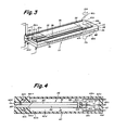
- a piezoceramic relay comprising a bimorph actuating member which is cantilever mounted in a generally rectangular enclosure or case formed of a suitable material such as glass, ceramic, or plastic. Carried at the free end of the bimorph member is at least one and preferably a set of two movable relay contacts which are poised in gapped relation with a pair of stationary contacts precisely, positional mounted by the case.
- a Form H contact arrangement wherein, with the bimorph member unenergized, the movable contacts are stationed in neutral, center "off" positions in spaced relation with their respectively associated fixed contacts.
- the bimorph member Upon selective energization of the bimorph member, it flexes in bender-like fashion to engage one or the other of the mating sets of fixed and movable contacts to route current through one of two load circuits wired therewith. Upon de-energization, the bimorph member returns to its centre "off" position.
- the invention can be embodied in various forms to provide a case that is moisture-proof or hermetically sealed to contain a vacuum or a protective gaseous atmosphere in which the relay contacts can operate.
- the invention is also directed to embodiments wherein the mounted end of the bimorph member extends extremally of its case through a sealed opening therein to expose its various electrodes for engagement by contact elements of a plug receptacle.
- Conductor runs connected with the fixed and movable contacts and supported on the case interior surfaces or on unelectroded surfaces of the bimorph member are also brought out through sealed case feedthrough openings for engagement with other contact elements of the same plug recepacle.
- the gaps are precisely set during the manufacturing process by the inclusion of accurately dimensioned spacers in each contact gap.
- the bimorph member is constrained by these spacers to assume a well defined neutral position with its movable contacts uniformly gapped relative to their association fixed contacts.
- the spacers are then physically removed intact or formed of a material which can be dissolved by an appropriate solvent, etched away, or vaporized by a focused laser beam.
- a piezoceramic relay includes a bimorph actuating member, generally indicated at 22 and consisting of a pair of piezoceramic plates 24 and 26 bonded together in sandwich fashion with a common, intervening surface electrode 28.
- the exposed upper surface of plate 24 is coated with a conductive metal to provide an electrode 30, while the exposed lower surface of plate 26 is similarly electroded, as indicated at 32.
- the plates are formed of known piezoceramic materials such as lead zirconate titanate (PZT), lead metaniobate, and barium titanate, while the surface electrodes are provided by deposited coatings of suitable metal, such as nickel, silver and the like.
- PZT lead zirconate titanate
- lead metaniobate lead metaniobate
- barium titanate barium titanate
- Bimorph member 22 is cantilever mounted adjacent one end by a wall 34 of an enclosure or case, generally indicated at 36. Affixed to the free end of member 22 is a contact carrier 38 which supports a pair of opposed movable contacts 40a and 40b. As seen in FIGURE 1, contact carrier 38 is formed of a suitable, structurally rigid plastic with a transverse slot 38a at one end for accepting the free end of bimorph member 22. This assembly of the contact carrier to the bimorph member is sustained with a suitable adhesive such as epoxy cement. The other end of the contact carrier is formed with a transverse slot 38b for accepting a copper plate 40 with movable contacts 40a and 40b affixed in electrical connection to its opposed surfaces.
- contact carrier 38 is notched, as indicated at 38c, to provide clearance for the movable contacts.
- Plate 40 is likewise adhesively bonded in place. It is seen that contact carrier 38 is constructed to provide a low profile assembly of the movable contacts to the bimorph member and thus affords a minimum height dimension for case 36.
- Case 36 is constructed from, in addition to endwall 34, an opposed endwall 41, a top wall 42a, a bottom wall 42b, and a pair of sidewalls 44, all joined together to form a generally retangular, box-like enclosure.
- These case walls may be formed of glass, ceramics such as berylium oxide, alumina, steatite, or a high performance, engineered plastic such as ULTEM, a polyetherimide.
- ULTEM is a registered trademark of the General Electric Company.
- glass walls they may be joined together with a glass frit to provide a moisture-proof and even a hermetic enclosure.
- Ceramic and ULTEM plastic walls may be joined with a variety of bonding agents or selectively copper plated and soldered together. Either approach is capable of providing a case 36 of sufficient hermeticity to sustain a vacuum or a protective gaseous atmosphere of inert gas such as dry nitrogen or a high strength dielectric gas such as sulfurhexaflouride.
- endwall 34 is formed in two parts 34a and 34b which are respectively provided with opposed notches 34c closely dimensioned to securely clamp bimorph member 22 between the wall parts when they are joined together along seam 34d.
- the terminal portion of the bimorph member extends sealingly (hermetically) through and beyond endwall 34 to present its surface electrodes 28, 30 and 32 extremally of case 36.
- Piezoceramic plate 24 is notched, as indicated at 24a, to expose electrode 28.
- a conductor run or strip 46 is affixed to the inner surface of top wall 42, while a similar conductor run 48 is afficed to the inner surface of bottom wall 42b.
- Affixed to the inner end portion of conductor run 46 is a stationary contact 50a for disposal in gapped relation to movable contact 40a.
- a second stationary contact 50b is affixed to the inner end portion of conductor run 48 where it is positioned in gapped relation to movable contact 40b.
- the outer ends of these conductor runs exit case 36 at the seams between back wall 34 and the top and bottom walls to present terminal portions 46a and 48a externally of the case.
- a third conductor run 52 is affixed to the inner surface of bottom wall 42b and extends from a terminal portion 52a disposed externally of the case to an inner end terminating short of end wall 41 where electrical connection with movable contact carrier plate 40 is effected via a flexible, flying lead 54.
- the relay case is formed of ceramic walls, excellant heat sinking of the relay contacts is afforded. Normally, electromagnetic relays do not offer any convenient way of heat sinking its contacts for increased life and load rating. This results from the conflicting requirements of electrical isolation between the contacts and the desire for a high thermal conductivity contact mounting part which is typically formed of plastic, a poor thermal conductor.
- the electrodes of bimorph member 22 and the terminal portions of the various conductor runs are made available beyond endwall 34 in positions conveniently accessible to contact elements of a plug receptacle, indicated at 54.
- contact element 54a can make electrical connection with terminal portion 46a of conductor run 46, contact element 54b with surface electrode 30, contact element 54c with surface electrode 28 made accessible via notch 24a, contact element 54d with surface electrode 30, and contact element 54e with terminal portion 48a of conductor run 48.
- a separate contact element of plug receptacle engages terminal portion 52a of conductor run 52.
- the piezoceramic relay construction seen in FIGURES 1 and 2 provides for convenient plug-in installation in complex electrical equipment, such as panelboards, printed circuit boards and the like.
- Figure 3 illustrates an alternative approach to bringing circuit connections through case endwall 34 (FIGURE 2) to movable contacts 40a, 40b and fixed contacts 50a, 50b. Instead of affixing the current feeding conductor runs to the top and bottom case walls, they are applied to unelectroded surfaces of bimorph member 22.
- surface electrode 30 is reduced in size to make available marginal surfaces portions of piezoceramic plate 24 for carrying conductor run 46 to feed fixed contact 50a via a flying lead 46b; this fixed contact being appropriately located and affixed to the inner surface of case top wall 42a (FIGURE 1).
- Surface electrode 32 is likewise reduced in size to make available electrode-free surface portions of piezoceramic plate 26 for carrying conductor run 48 to feed fixed contact 50b via flying lead 48b.
- Contact 50b is similarly affixed to the inner surface of case bottom wall 42b.
- FIGURE 3 Also shown in FIGURE 3 is the alternative approach of mounting movable contacts 40a and 40b to unelectroded surface portions of plates 24 and 26, respectively, rather than via contract carrier 38 of FIGURE 1.
- a conductor run 56 is applied to the unelectroded marginal surface portion of plate 24, while movable contact 40b is feed by a conductor run 58 applied to the unelectroded marginal surface portion of plate 26.
- the two sets of fixed and movable contacts seen in FIGURE 3 may be adapted to operate in complete separate circuits since the two movable contacts are not electrically common.
- the movable contacts may be shorted together by a conductive, U-shaped clip, indicated in phantom at 40c, in which case one of the conductor runs 56 or 58 can be eliminated.
- bimorph member 22 in FIGURE 2 may be equipped with movable contact carrier 38 of FIGURE 1, in which case a jumper (not shown) would be used to connect conductor run 56 or 58 to contact carrier plate 40.
- FIGURE 3 further illustrates the modification of recessing the surface electrodes 30 and 32 back from the terminal end of the bimorph member, such that only electrical termination portions thereof, indicated at 30a and 32a, are carried through case end wall 34.
- This has the advantege of rendering the portions of the piezoceramic plates passing through the case end wall substantially unpoled and electrically neutral.
- these passthrough portions of the plates by design, remain relatively physically inactive during relay operation, and consequently the integrity of the cantilever mounting of the bimorph member is not degraded over time. That is, there is no physical motion of this portion of the bimorph member tending to induce fracture or cracking of the case endwall.
- FIGURE 3 diagrammatically represent receptacle contact elements which are adapted to make electrical contact with electrode terminal portions 30a and 32a, electrode 28, and the terminal portions of the various conductor runs.
- FIGURE 4 illustrates an alternative packaging approach wherein the body, generally indicated at 60, of a relay enclosure is configured such as to be capable of being injection mold in one piece of a suitable, highly stable engineered plastic, such as polyetherimide (ULTEM).
- body 60 is formed with a carefully dimensioned blind slot 60a in which one end of bimorph member 22 is snugly received and bonded in place to effect the requisite cantilever mounting thereof.
- Slot 60a opens into a large cavity 60b providing adequate space for the bimorph member to flex during relay operation. This cavity is closed off beyond the free end of the bimorph member by an end wall 62 in which are formed three blind, narrow slots 62a, 62b and 62c.
- slot 62a Fitted into slot 62a is a relatively rigid copper strap 64a which serves to mount at its inner end fixed contact 50a.
- Slot 62c receives a like copper strap 64c which serves to mount fixed contact 50b.
- Received in slot 62b is a copper strap 64b which is electrically connected via a flying lead 65 to conductive carrier plate 40 to which movable contacts 40a and 40b are affixed in opposed relation. As described in FIGURE 1, this carrier plate is supported by a contact carrier 38 which, in turn is mounted to the free end of bimorph member 22 with the fixed and movable contacts in appropriately gapped relation.
- the side walls of slot 60a are formed with opposed concavities 60c to afford access to surface electrodes 30 and 32 for the connections thereto of lead-in conductors 66a and 66b.
- These conductors may be brought out via through sealable holes (not shown) formed in the closed side 60d of body which concavities 60c are reduced down to. Alternatively, these conductors may be brought out through the open side which may be ultimately, sealingly closed off by a suitable cover (not shown). Connection to common electrode 28 is made by a lead 66 as illustrated.
- FIGURE 5 illustrates yet another hermetic packaging approach wherein one end of bimorph member 22 is adhesively bonded or soldered to a pedestal 68 which, in turn, is affixed to the case bottom wall 70 to effect the requisite cantilevered mounting.
- the left endwall is comprised of two sections 72a and 72b bonded together along a seam 72c in which the entry of a lead-in conductor 74a, connected with common electrode 28, is sealingly accommodated.
- the bonding seam between end wall section 72b and bottom wall 70 accommodates a lead-in conductor 74b, which is connected via a flying lead 75a to surface electrode 32.
- the bonding seam between end wall section 72a and case top wall 76 sealingly admits lead-in conductor 74c, which is connected to surface conductor 30 via flying lead 75b.
- the opposite end wall is similarly comprised of two sections 78a and 78b, with the seam therebetween sealingly admitting a lead-in conductor 80a, which is connected via a flying lead 81 to a U-shaped copper clip 82 affixed on the free end of bimorph member 22. Movable contacts 40a and 40b are affixed in electrical connection to clip 82. As illustrated, electrical clearance is provide between this clip and the bimorph electrodes 28, 30 and 32.
- the seam between end wall section 78a and top wall 76 sealing admits a conductive strap 84a which mounts at its inner end stationary contact 50a in appropriately gapped relation with movable contact 40a.
- the seam between end wall section 78b and bottom wall 70 accommodates a strap 84b to which stationary contact 50b is mounted in gapped relation with movable contact 40b.
- the case walls which may be formed of a suitable engineered plastic such as polyetherimide (ULTEM), are coated with a layer of metal, such as copper 86, to provide shielding against the emission of undesired electromagnetic interference waves produced by the commutation of load currents during relay operation.
- a suitable isolating material such as a bead 86a of polymide silane, is applied to these conductors at their points of exit from the case.
- FIGURE 5 also illustrates that a hermetic header 88 may be applied to the relay case to insure that the presence of the various lead-in conductors does not jeopardize the hermeticity of the relay case.
- This header may take the form of a metallic boot 88a which is fitted on the end of the relay case and sealed in place by a continuous bead of solder 89. Leads 88b admitted through hermetically sealed openings in the closed end of the boot may then be connected by jumpers 90 at the exposed ends of the lead-in conductors penetrating the relay case.
- the bimorph member 22 is cantilever mounted in the case end wall in the manner described in FIGURES 1 and 2. As shown, surface electrodes 30 and 32 are terminated short of this end wall, such that the end section of the bimorph member clamped therein is relatively physically inactive during relay operation. Surface electrodes 30 and 32 are illustrated as being brought out electrically via flying leads and lead-in conductors in the manner described in FIGURE 5. The same is true for stationary contacts 50a and 50b. Movable contacts 40a and 40b are affixed to the free end of bimorph member 22 via metal clap 82, again in the manner of FIGURE 5.
- movable contacts 40a, 40b and the common electrode may be connected in common, as indicated at 82a in FIGURE 6.
- the common electrode can doubly serve as the lead-in conductor for the movable contacts, thus eliminating one electrical feedthrough penetrating the relay case and the need for a flying lead connected with the movable contacts.
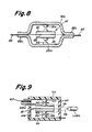
- FIGURE 7 illustrates that bimorph member 22 need not carry switching contacts, but instead may be adapted to actuate an external switch or switches 92 via a pushrod(s) 94 penetrating the bimorph mounting enclosure 96 by way of openings 96a.
- Switches 92 may be bistable switches, in whch case only momentary actuation of the bimorph member is necessary to change the switch condition.
- the actuated switch condition may be sustained by maintaining the electric field across one of the piezoceramic plates; a situation which involves minimal power consumption.
- bimorph member 22 is shown packaged in a sag glass case, consisting of a base 98a and a cover 98b sealed together along their flanged edges 98c by suitable means, such as a glass frit seal.
- these glass case members are formed by heating a glass plate disposed over a concave mold cavity, causing the medial portion of the plate to sag downwardly into conformity with the contour of the mold cavity.
- Lead-in conductors 100 on which the stationary contacts 50a and 50b are affixed, are conformed to the case contour and brought out through the seam between the base and cover flanges 98c.
- the glass frit seal will readily accept the lead-in conductor thickness while perfecting the case hermetic seal. It will be appreciated that the base 98a and cover 98b are formed with opposed notches (not shown) analogous to notches 34c in FIGURES 1 and 2, in which one end of the bimorph member is received and sealed in place by glass frit, pursuant to effecting its cantilevered mounting.
- the bimorph member be prepolarized in situ, i.e., after the relay has been completely assembled.
- the temperature of the bimorph member is raised to just above the Curie temperature of the piezoceramic plates and then lowered to just below this Curie temperature while the requisite prepolarizing potentials are applied to surface electrodes 28, 30 and 32.
- bimorph prepolarization can be accomplished at room temperature and without the bimorph member having to be immersed in an insulating oil bath.
- a spacer 100 is positioned between each set of fixed and movable contacts, as seen in FIGURE 9. The prepolarizing step is then performed with these spacers in place.
- these spacers can be accurately dimensioned in thickness to take up the remaining available space and thus establish a uniform gap dimension and incidentally the desired center positioning of the bimorph free end in its neutral state.
- spacers 100 may be removed from the case utilizing a suitable tool (not shown) introduced through a nipple 103 sealed in an opening 104a formed in a case side wall 104.
- the spacers may be dissolved utilizing an appropriate solvent introduced and subsequently removed via nipple 103.
- An appropriate etchant could also be utilized to eliminate the spacers.
- a water soluble alumina is available from TAFA Inc. of Concord, New Hampshire. This being accomplished, the relay is baked out at temperatures sufficiently low as not to damage the piezoceramic plate elements, and the case is evacuated via nipple 103.
- the case can be back filled with an inert or high dielectric strength gas. Nipple 103 is then pinched off to hold the vacuum or protective gas atmosphere within the hermetic relay case. Alternatively, the spacers may simply be physically removed from the contact gaps and left in the case to serve as a getter.
- the relay case may be hermetically sealed after bakeout and evacuation with spacers 100 left in place.
- a focused laser beam 106 of appropriated wavelength is then directed through transparent sidewall 107 to vaporize the spacers 100.
- the spacer material is selected such that the condensed residue thereof will not be harmful to the relay parts.
- the vaporized spacers may be at least in part formed of a gettering material such as barium which would serve to absorb any outgases emitted by the case material over time.
- FIGURE 10 illustrates a packaging approach wherein integrated circuitry, generally indicated at 110, appropriate for actuating bimorph member 22, is copackaged with the relay parts within hermetic case 112. If the case is backfilled with an inert gas, e.g., dry nitrogen, the integrated circuit chips need not be individually packaged or conformal coated.
- an inert gas e.g., dry nitrogen
- the integrated circuitry is powered via lead-in conductors, commonly indicated at 114, which are introduced into the interior of case 112. Flying leads 116 connect the integrated circuitry to the surface electrodes 28, 30 and 32 of bimorph member 22.
- the integrated circuitry 110 may be copackaged externally of the case on an exterior surface thereof, such as an extension 118a of the case bottom wall 118, as illustrated in FIGURE 11.
- This circuitry is connected to the bimorph electrode via lead-in conductors 120 and flying leads 122.
- the interconnecting leads can be quite short, thus minimizing stray impedances. Inductive and capacitive coupling of noise into the integrated circuitry is also minimized for the same reason.
- each fixed contact may be replaced by a closely spaced, side-by-side, pair of fixed contacts which are bridged by a movable contact in the form of shorting bar carried at the free end of the bimorph member to complete a power circuit.
- This approach avoids the need for a flying lead to feed bimorph mounted movable contacts.
Landscapes
- Micromachines (AREA)
- Switch Cases, Indication, And Locking (AREA)
Applications Claiming Priority (2)
| Application Number | Priority Date | Filing Date | Title |
|---|---|---|---|
| US06/876,149 US4755706A (en) | 1986-06-19 | 1986-06-19 | Piezoelectric relays in sealed enclosures |
| US876149 | 1997-06-13 |
Publications (2)
| Publication Number | Publication Date |
|---|---|
| EP0249864A2 true EP0249864A2 (fr) | 1987-12-23 |
| EP0249864A3 EP0249864A3 (fr) | 1989-10-18 |
Family
ID=25367084
Family Applications (1)
| Application Number | Title | Priority Date | Filing Date |
|---|---|---|---|
| EP87108359A Withdrawn EP0249864A3 (fr) | 1986-06-19 | 1987-06-10 | Relais piézo-électriques en boítiers étanches |
Country Status (3)
| Country | Link |
|---|---|
| US (1) | US4755706A (fr) |
| EP (1) | EP0249864A3 (fr) |
| JP (1) | JPS6324523A (fr) |
Cited By (1)
| Publication number | Priority date | Publication date | Assignee | Title |
|---|---|---|---|---|
| WO1996001487A1 (fr) * | 1994-07-04 | 1996-01-18 | Powerbreaker Plc | Mecanisme de detente |
Families Citing this family (24)
| Publication number | Priority date | Publication date | Assignee | Title |
|---|---|---|---|---|
| US4845337A (en) * | 1988-02-02 | 1989-07-04 | Eg&G, Inc. | Ovenized oscillator assembly |
| DE3909262A1 (de) * | 1988-03-25 | 1989-10-12 | Gen Electric | Steuersystem, atmosphaerische kuehlvorrichtung und verfahren zum betreiben der kuehlvorrichtung |
| DE4038786A1 (de) * | 1990-12-05 | 1992-06-11 | Bsg Schalttechnik | Vorrichtung zur steuerung oder regelung von durch akkus versorgter geraete |
| US5444574A (en) * | 1991-09-19 | 1995-08-22 | Olympus Optical Co., Ltd. | Electronic image pickup apparatus equipped with means for eliminating moire |
| US5479042A (en) * | 1993-02-01 | 1995-12-26 | Brooktree Corporation | Micromachined relay and method of forming the relay |
| US5539270A (en) * | 1993-11-19 | 1996-07-23 | Matsushita Electric Works, Ltd. | Acceleration detector |
| CH686802A5 (de) * | 1994-01-20 | 1996-06-28 | Cerberus Ag | Koerperschallmelder fuer ein Einbruchalarmsystem. |
| US5883519A (en) * | 1996-02-23 | 1999-03-16 | Kinetic Probe, Llc | Deflection device |
| US5983722A (en) * | 1997-11-12 | 1999-11-16 | K.K. Holding Ag | Piezobloc accelerometer |
| US6198207B1 (en) * | 1998-09-01 | 2001-03-06 | Oceana Sensor Technologies | High-volume production, low cost piezoelectric transducer using low-shrink solder of bismuth or antimony alloy |
| US6359374B1 (en) | 1999-11-23 | 2002-03-19 | Mcnc | Miniature electrical relays using a piezoelectric thin film as an actuating element |
| US7256669B2 (en) * | 2000-04-28 | 2007-08-14 | Northeastern University | Method of preparing electrical contacts used in switches |
| CN100463704C (zh) * | 2001-09-24 | 2009-02-25 | 斯科特实验室公司 | 集成药物输送系统 |
| US7405759B2 (en) | 2001-09-28 | 2008-07-29 | Mosaic Imaging, Inc. | Imaging with spectrally dispersive element for aliasing reducing |
| JP3998948B2 (ja) * | 2001-10-31 | 2007-10-31 | セイコーインスツル株式会社 | 圧電振動子及びその製造方法 |
| AU2003272500A1 (en) * | 2002-09-18 | 2004-04-08 | Mark Goranson | Method of assembling a laminated electro-mechanical structure |
| US6894424B2 (en) * | 2003-04-14 | 2005-05-17 | Agilent Technologies, Inc. | High frequency push-mode latching relay |
| US6885133B2 (en) * | 2003-04-14 | 2005-04-26 | Agilent Technologies, Inc. | High frequency bending-mode latching relay |
| US7215229B2 (en) * | 2003-09-17 | 2007-05-08 | Schneider Electric Industries Sas | Laminated relays with multiple flexible contacts |
| US7342473B2 (en) * | 2004-04-07 | 2008-03-11 | Schneider Electric Industries Sas | Method and apparatus for reducing cantilever stress in magnetically actuated relays |
| KR100706608B1 (ko) * | 2005-07-19 | 2007-04-13 | 한국전자통신연구원 | 이중 스트림 전송에 적합한 부호기 추정 방법 및 이를이용한 부호화 장치 |
| US7868720B2 (en) * | 2007-11-01 | 2011-01-11 | Tyco Electronics Corporation India | Hermetically sealed relay |
| US10205082B2 (en) | 2016-04-20 | 2019-02-12 | Honeywell International Inc. | Constrained piezo-electric element to improve drive capability |
| CN115332020B (zh) * | 2022-08-26 | 2025-07-25 | 广州凯立达电子股份有限公司 | 一种压电陶瓷继电器 |
Family Cites Families (16)
| Publication number | Priority date | Publication date | Assignee | Title |
|---|---|---|---|---|
| US2835761A (en) * | 1953-05-25 | 1958-05-20 | Electric Machinery Mfg Co | Electrostrictive ceramic actuator |
| GB959714A (en) * | 1962-02-16 | 1964-06-03 | Standard Telephones Cables Ltd | Improvements in or relating to light-current contact-making relays |
| GB1096824A (en) * | 1964-03-26 | 1967-12-29 | Plessey Uk Ltd | Improvements in electric relays |
| US3359435A (en) * | 1965-05-04 | 1967-12-19 | James E Webb | Holder for crystal resonators |
| JPS46411Y1 (fr) * | 1966-01-17 | 1971-01-08 | ||
| US3777093A (en) * | 1972-05-25 | 1973-12-04 | R Sterns | Electromechanical relay |
| US3970880A (en) * | 1973-09-07 | 1976-07-20 | Motorola, Inc. | Crystal mounting structure and method of assembly |
| US4093883A (en) * | 1975-06-23 | 1978-06-06 | Yujiro Yamamoto | Piezoelectric multimorph switches |
| DE2537760A1 (de) * | 1975-08-25 | 1977-03-10 | Siemens Ag | Piezoelektrischer motor |
| JPS5421295A (en) * | 1977-07-19 | 1979-02-17 | Matsushima Kogyo Kk | Crystal oscillator |
| DE2749428C2 (de) * | 1977-11-04 | 1980-06-12 | Siemens Ag, 1000 Berlin Und 8000 Muenchen | Halterungsvorrichtung für einen plattenförmigen Resonator |
| GB2012106B (en) * | 1977-12-06 | 1982-06-23 | Sony Corp | Electro-mechanical transducers |
| US4405875A (en) * | 1980-07-24 | 1983-09-20 | Kiyoshi Nagai | Hermetically sealed flat-type piezo-electric oscillator assembly |
| US4461968A (en) * | 1982-01-11 | 1984-07-24 | Piezo Electric Products, Inc. | Piezoelectric relay with magnetic detent |
| JPS6046636U (ja) * | 1983-09-05 | 1985-04-02 | オムロン株式会社 | 多極リレ− |
| US4658154A (en) * | 1985-12-20 | 1987-04-14 | General Electric Company | Piezoelectric relay switching circuit |
-
1986
- 1986-06-19 US US06/876,149 patent/US4755706A/en not_active Expired - Fee Related
-
1987
- 1987-06-01 JP JP62134994A patent/JPS6324523A/ja active Pending
- 1987-06-10 EP EP87108359A patent/EP0249864A3/fr not_active Withdrawn
Cited By (1)
| Publication number | Priority date | Publication date | Assignee | Title |
|---|---|---|---|---|
| WO1996001487A1 (fr) * | 1994-07-04 | 1996-01-18 | Powerbreaker Plc | Mecanisme de detente |
Also Published As
| Publication number | Publication date |
|---|---|
| JPS6324523A (ja) | 1988-02-01 |
| US4755706A (en) | 1988-07-05 |
| EP0249864A3 (fr) | 1989-10-18 |
Similar Documents
| Publication | Publication Date | Title |
|---|---|---|
| US4755706A (en) | Piezoelectric relays in sealed enclosures | |
| US6426537B2 (en) | Ultra-thin piezoelectric resonator | |
| EP1283539B1 (fr) | Relais statique et dispositif de communication utilisant ledit relais statique | |
| US6689976B1 (en) | Electrically isolated liquid metal micro-switches for integrally shielded microcircuits | |
| GB2292010A (en) | Ceramic package for a semiconductor device | |
| US4451754A (en) | High frequency piezoelectric resonator | |
| US3320351A (en) | Miniature circuit housing | |
| US4680840A (en) | Method for prepolarizing and centering a piezoceramic power switching device | |
| US2678360A (en) | Vibrator | |
| US7990240B2 (en) | Epoxy sealed relay | |
| US4134088A (en) | Miniature magnetic mercury-wetted relay construction | |
| USRE33587E (en) | Method for (prepolarizing and centering) operating a piezoceramic power switching device | |
| US5289145A (en) | Electromagnetic relay and a method for its production | |
| US4689517A (en) | Advanced piezoceramic power switching devices employing protective gastight enclosure and method of manufacture | |
| EP0829091A1 (fr) | Microcommutateur commande, procede pour le fabriquer et son utilisation | |
| US4812794A (en) | Electrical relay apparatus | |
| JPH0832138A (ja) | 圧電振動子 | |
| GB2040560A (en) | Piezoelectric tuning fork resonator | |
| US4725701A (en) | Low voltage vacuum circuit interrupter | |
| USRE33577E (en) | Advanced piezoceramic power switching devices employing protective gastight enclosure and method of manufacture | |
| EP0236075A3 (fr) | Appareil interrupteur de relais | |
| JPS6273518A (ja) | 低電圧真空回路遮断器 | |
| US4705923A (en) | Low voltage vacuum circuit interrupter | |
| CN115812243A (zh) | 密闭型电磁接触器 | |
| EP4560678A1 (fr) | Contacteurs à courant continu à voies d'évacuation d'air améliorées |
Legal Events
| Date | Code | Title | Description |
|---|---|---|---|
| PUAI | Public reference made under article 153(3) epc to a published international application that has entered the european phase |
Free format text: ORIGINAL CODE: 0009012 |
|
| AK | Designated contracting states |
Kind code of ref document: A2 Designated state(s): DE FR GB NL |
|
| PUAL | Search report despatched |
Free format text: ORIGINAL CODE: 0009013 |
|
| AK | Designated contracting states |
Kind code of ref document: A3 Designated state(s): DE FR GB NL |
|
| 17P | Request for examination filed |
Effective date: 19900331 |
|
| STAA | Information on the status of an ep patent application or granted ep patent |
Free format text: STATUS: THE APPLICATION HAS BEEN WITHDRAWN |
|
| 18W | Application withdrawn |
Withdrawal date: 19910104 |
|
| RIN1 | Information on inventor provided before grant (corrected) |
Inventor name: KORNRUMPF, WILLIAM PAUL Inventor name: HARNDEN, JOHN DAVIS JR. |